
I. Function and Classification
A hydraulic motor is an actuator that converts pressure energy into mechanical energy to perform work externally. In principle, it is reversible with a hydraulic pump and structurally similar. However, in practical applications, except for axial piston pumps and motors which can be used interchangeably, others cannot. This is because hydraulic pumps and motors operate under different conditions and have distinct performance requirements. Hydraulic motors generally need to support forward and reverse rotation, with symmetrical internal structures, a wide speed regulation range, and no self-priming capability. They require a certain initial sealing to provide the necessary starting torque. Hydraulic motors are typically divided into two categories: high-speed and low-speed.
High-speed hydraulic motors, with rated speeds above 500 r/min, include gear, screw, vane, and axial piston types. They feature high rotational speed, high power density, low moment of inertia, small displacement, and ease of starting, braking, speed regulation, and reversing. However, their output torque is relatively low, typically ranging from tens to hundreds of Nm, which often cannot directly meet the torque and speed requirements of engineering loads, necessitating a reduction mechanism. This limits their applications. Low-speed hydraulic motors, with rated speeds below 500 r/min, have large displacement and volume but can deliver thousands to tens of thousands of Nm of torque even at a few revolutions per minute. These are commonly referred to as low-speed, high-torque hydraulic motors. Their main types include multi-action inner curve piston (or ball) motors and crankshaft-connecting rod or hydrostatic balance radial piston motors. These are suitable for directly connecting and driving loads with short starting and acceleration times and excellent performance, making them widely used in engineering practice.
II. Structure and Working Principle of Hydraulic Motors
Since the structure of hydraulic motors is similar to that of hydraulic pumps, this section uses the fixed-displacement axial piston motor with a swashplate as an example to explain its working principle and structure.
1.Working Principle
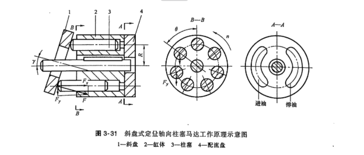
Figure 3-31 illustrates the working principle of a fixed-displacement axial piston motor with a swashplate. When hydraulic oil enters the motor’s inlet, the plungers (3) corresponding to the inlet chamber of the distribution plate (4) are pushed out by hydraulic pressure and press against the swashplate (1). The swashplate generates a normal reaction force (F) on the plungers, which can be resolved into horizontal and vertical components. The horizontal component balances the hydraulic force, while the vertical component is transmitted through the plungers to the cylinder block (2), producing torque on the drive shaft. Since each plunger is at a different position, the torque generated varies, and the motor’s output torque is the sum of the instantaneous torques produced by all plungers in the inlet chamber acting on the drive shaft.
2.Structure
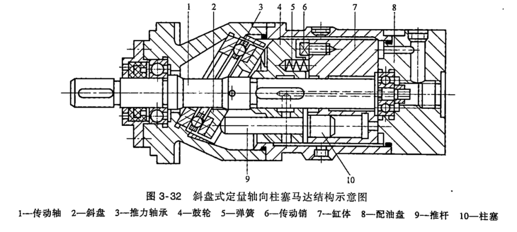
The typical structure of a fixed-displacement axial piston motor with a swashplate is fully interchangeable with the MCY14-1B series hydraulic pump. Figure 3-32 shows a schematic of its structure, with the following features:
<1>The motor’s cylinder block is divided into two parts: the front part, called the drum (4), and the rear part, called the cylinder block (7). The drum is connected to the drive shaft via a flat key, and the cylinder block (7) is linked to the drum (4) via a drive pin (6). A spring (5) compensates for axial clearance in the distribution plate. Similarly, the plungers are divided into two parts: those in the drum (4) are called pushrods (9), and those in the cylinder block (7) are called plungers (10). The pushrods (9), under the action of the plungers (10), contact the swashplate (2). Since the cylinder block (7) and plungers (10) bear only axial forces, while the pushrods (9) and drum (4) bear both axial and radial forces, the pushrods and drum can transmit torque.
<2>A thrust bearing (3) is installed between the swashplate (2) and the housing. During operation, the rigid contact between the pushrods (9) and the swashplate (2) reduces frictional losses.
III. Comparison of Hydraulic Pumps and Hydraulic Motors
1.Similarities0
<1>In principle, hydraulic motors and pumps are reversible. When driven by an electric motor, they output hydraulic energy (pressure and flow), functioning as a pump. When hydraulic oil is input, they output mechanical energy (torque and speed), functioning as a motor.
<2>Structurally, they are similar.
<3>Both operate by utilizing changes in sealed working volumes for oil suction and discharge. For a pump, oil is sucked in when the working volume increases and high-pressure oil is discharged when it decreases. For a motor, high-pressure oil enters when the working volume increases, and low-pressure oil is discharged when it decreases.
2.Differences
<1>A hydraulic pump converts mechanical energy from an electric motor into hydraulic energy, outputting flow and pressure, with a focus on high volumetric efficiency. A hydraulic motor converts hydraulic pressure energy into mechanical energy, outputting torque and speed, with a focus on high mechanical efficiency. Thus, a pump is an energy device, while a motor is an actuator.
<2>A hydraulic motor’s output shaft must support both forward and reverse rotation, so its structure is symmetrical. Some hydraulic pumps (e.g., gear pumps, vane pumps) have a fixed rotation direction and cannot reverse arbitrarily.
<3>Hydraulic motors have separate leakage oil ports in addition to inlet and outlet ports, while pumps typically have only inlet and outlet ports (except for axial piston pumps), with internal leakage oil connected to the inlet.
<4>Hydraulic motors have lower volumetric efficiency than pumps. Pumps typically operate at higher speeds, while motors have lower output speeds.
<5>In terms of specific structural details: gear pumps have a larger suction port and smaller discharge port, while gear motors have identical inlet and outlet port sizes; gear motors have more teeth than gear pumps; vane pump blades must be installed at an angle, while vane motor blades are installed radially; vane motor blades are pressed against the stator surface by root springs, while vane pump blades are pressed by hydraulic oil and centrifugal force at the root.
3.Graphical Symbols for Hydraulic Pumps and Motors
The graphical symbols for hydraulic motors are similar to those for hydraulic pumps. However, hydraulic motors input hydraulic oil, while pumps output it. In the symbols, the direction of the black triangular arrow indicates the flow direction of hydraulic oil (input for motors, output for pumps).
“A leader in hydraulic technology, A convenient choice around you”