
Chapter 1: Introduction to Hydraulic Transmission
When engineers and technicians ask "what is hydraulics," they are inquiring about one of the most powerful and versatile transmission methods in modern mechanical engineering. Hydraulic transmission possesses numerous advantages compared to mechanical transmission systems, which explains its widespread adoption across various industries and applications.
Hydraulic transmission represents a sophisticated method of power transfer that utilizes liquid as the working medium to transmit energy efficiently. This transmission form operates through energy conversion devices, such as hydraulic pumps, which transform the mechanical energy from prime movers (like electric motors) into liquid pressure energy. Subsequently, through closed pipelines and control elements, another energy conversion device (such as hydraulic cylinders or hydraulic motors) converts the liquid pressure energy back into mechanical energy to drive loads and achieve the required linear or rotational motion of actuating mechanisms.
Understanding what is hydraulics becomes essential for modern engineers, as this technology forms the backbone of countless industrial applications. The fundamental principle behind hydraulic systems lies in Pascal's law of hydrostatic pressure transmission, which enables the multiplication of force through fluid mechanics principles.
This comprehensive examination covers the development history of hydraulic transmission, its operational principles, system composition, advantages and disadvantages, and the extensive applications of hydraulic technology across various sectors of modern industry.
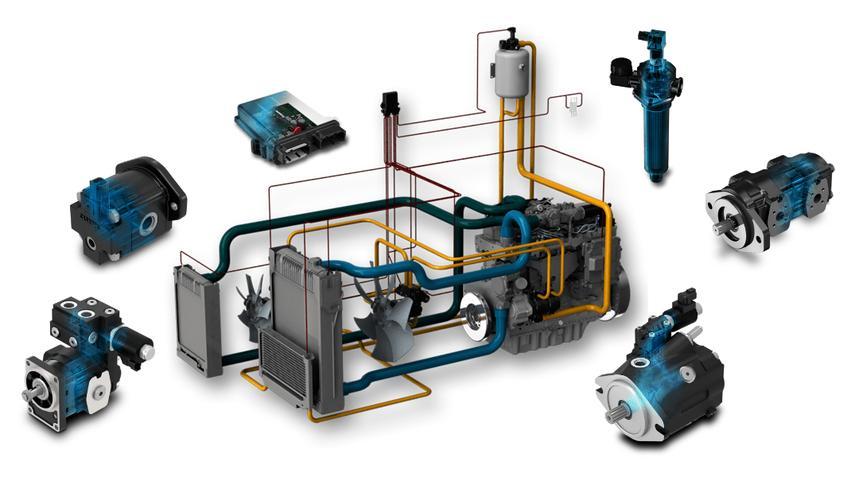
Modern hydraulic systems power a wide range of industrial machinery with precision and efficiency
Section 1: Historical Development of Hydraulic Transmission
Relative to mechanical transmission systems, hydraulic transmission represents a relatively modern technological advancement. The origins of hydraulic transmission can be traced back to 1654 when Pascal proposed the fundamental principle of hydrostatic pressure transmission. This groundbreaking concept laid the theoretical foundation for all future hydraulic developments.
The practical implementation of hydraulic principles began in 1795 with the emergence of the first hydraulic press in Britain. However, the technology remained limited until 1905, when engineers made the crucial decision to replace water with oil as the working medium. This substitution resulted in dramatic performance improvements and marked a turning point in hydraulic technology development.
The widespread adoption and application of hydraulic transmission systems benefited significantly from the petroleum industry that emerged and flourished during the 19th century. The availability of refined oils provided the necessary working fluids that made hydraulic systems practical and reliable for industrial applications.
The earliest successful application of hydraulic transmission devices occurred in naval vessels, specifically in gun turret positioning systems. These applications demonstrated the superior control capabilities and power transmission efficiency that hydraulic systems could provide in demanding military environments.
During World War II, military industrial requirements for rapid response, high precision, and high-power hydraulic transmission devices further accelerated the development of hydraulic technology. The demands of warfare pushed engineers to develop more sophisticated and reliable hydraulic systems, leading to significant technological breakthroughs.
Following the war, hydraulic technology rapidly transitioned to civilian applications and gradually gained widespread adoption across various sectors of the national economy. The 1960s marked another significant period of advancement, as developments in atomic energy, space technology, and computer technology drove corresponding innovations in hydraulic systems, leading to their penetration into virtually every industrial field.
Currently, hydraulic technology continues evolving toward higher speeds, higher pressures, greater power output, improved efficiency, reduced noise levels, extended service life, increased integration, compound functionality, digitization, miniaturization, and weight reduction. Additionally, contemporary research focuses on new hydraulic components and systems incorporating computer-assisted testing (CAT), computer direct control (CDC), mechatronic integration, computer simulation and optimization design techniques, environmentally friendly water-based transmission technology based on green manufacturing principles, and advanced contamination control methods.
China's hydraulic technology development began in 1952, with hydraulic components initially applied to machine tools and forging equipment before expanding to construction machinery. In 1964, China imported hydraulic component production technology from foreign countries while simultaneously developing domestic hydraulic products through independent design efforts.
Through years of dedicated development, particularly following the introduction of advanced technology and equipment from the United States, Japan, and Germany in the early 1980s, China's hydraulic technology reached new heights. Currently, China has established comprehensive standardized, serialized, and universalized hydraulic component product lines covering all major categories.
Timeline of Hydraulic Technology Development
1654
Pascal proposes the fundamental principle of hydrostatic pressure transmission
1795
First hydraulic press emerges in Britain, marking practical implementation of hydraulic principles
1905
Engineers replace water with oil as the working medium, dramatically improving performance
World War II
Military requirements drive significant advancements in hydraulic technology
1960s
Hydraulic systems integrate with atomic energy, space, and computer technologies
1980s-Present
Digitalization, miniaturization, and environmental improvements drive hydraulic innovation
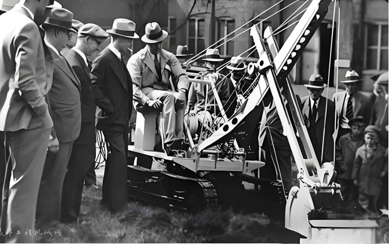
Early hydraulic machinery paved the way for modern industrial applications
Section 2: Working Principles and Composition of Hydraulic Transmission
I. Working Principles of Hydraulic Transmission
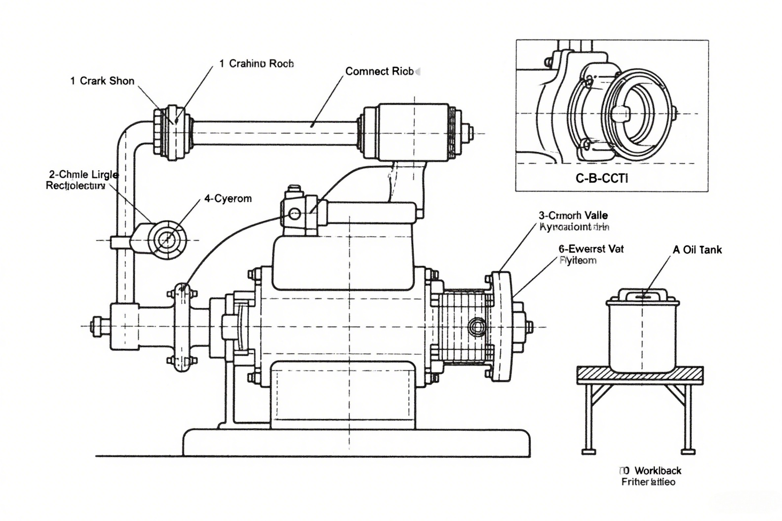
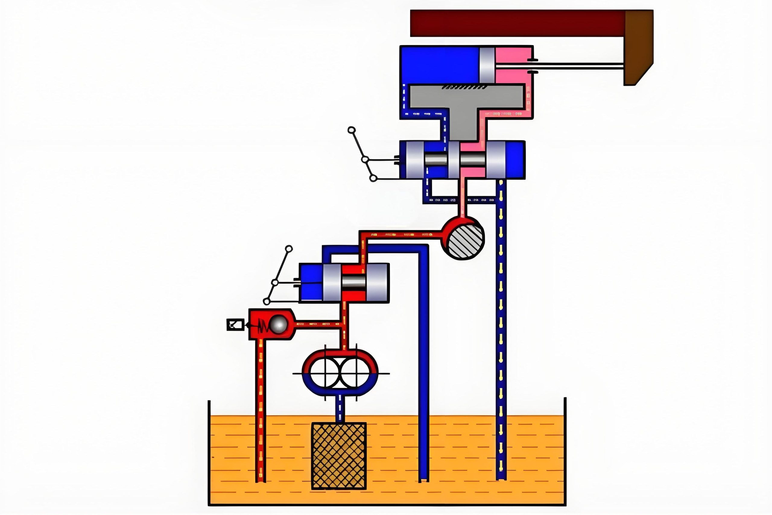
To understand what is hydraulics in practical terms, we can analyze a simple hydraulic transmission system designed for a machine tool that achieves reciprocating motion of a worktable. This system demonstrates the fundamental operating principles that govern all hydraulic applications.
In this representative system, the hydraulic cylinder remains fixed to the machine bed, while the piston and piston rod combination drives the worktable in linear reciprocating motion. An electric motor drives the hydraulic pump rotation, which draws oil from the tank through a mesh filter. The oil flows through a throttle valve to reach a directional control valve.
When the manual handle occupies the neutral position, the pump port (P) remains disconnected from ports A, B, and the tank return (T). Under these conditions, the hydraulic cylinder receives no oil supply, resulting in stationary worktable operation.
Moving the handle to position the system for rightward motion creates a flow path from P to A, directing oil to the left chamber of the hydraulic cylinder. Simultaneously, oil from the right chamber returns through port B to the tank via port T, causing rightward worktable movement.
Conversely, positioning the handle for leftward motion establishes flow from P to B, supplying oil to the right chamber of the hydraulic cylinder. The left chamber returns oil through port A to the tank via port T, resulting in leftward worktable movement.
This analysis demonstrates that the directional control valve enables hydraulic oil path changes, allowing continuous hydraulic cylinder direction reversals to achieve worktable reciprocating motion. The worktable speed can be regulated through the throttle valve, which controls oil flow rate by adjusting the throttle opening size.
During worktable operation, the system must overcome resistance forces, cutting forces, and surface friction between relatively moving components. The hydraulic pump output pressure overcomes these resistive forces, with pressure adjustability based on varying operating conditions. Additionally, hydraulic pump output often exceeds hydraulic cylinder requirements, with excess oil returning to the tank through the relief valve.
Key Principles of Hydraulics
- Hydraulic transmission relies on moving liquid pressure energy for power transmission, distinguishing it from "hydrodynamic transmission" which utilizes liquid kinetic energy for power transfer.
- During hydraulic system operation, hydraulic pumps convert mechanical energy to pressure energy, while executive elements (hydraulic cylinders) convert pressure energy back to mechanical energy.
- Oil in hydraulic transmission systems operates under regulated and controlled conditions, making hydraulic transmission and control inseparable aspects of system design.
- Hydraulic transmission systems must satisfy the force and speed requirements of the machine components (worktables) they drive.
- Hydraulic transmission requires working media, using liquid as the medium for signal and power transmission.
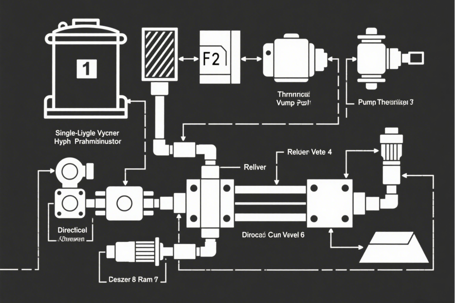
Hydraulic systems convert mechanical energy to fluid pressure and back to mechanical motion
II. Composition of Hydraulic Transmission Systems
From the preceding example, hydraulic transmission systems comprise five essential components:
Power Source Device
This component converts mechanical energy into oil pressure energy. The most common example is the hydraulic pump, which provides hydraulic oil to the entire system, enabling overall system operation and functionality.
Executive Device
These components convert oil pressure energy into mechanical energy while performing external work, including hydraulic cylinders and hydraulic motors that serve as the primary actuating elements.
Control Devices
These elements control oil pressure, flow rate, and flow direction within hydraulic systems. Examples include directional control valves, throttle valves, relief valves, and other hydraulic components.
Auxiliary Devices
These encompass all components beyond the three primary categories, including mesh filters, oil pipelines, and other elements that ensure reliable, stable, and durable hydraulic system operation.
Working Medium
This consists of hydraulic oil or other synthetic liquids that serve as the energy transmission medium throughout the system. The working medium is crucial for transferring power efficiently while lubricating system components.
Each component plays a crucial role in answering what is hydraulics from a practical system perspective, demonstrating how these elements work together to create functional hydraulic transmission systems.
Section 3: Graphical Symbols for Hydraulic Transmission Systems
The hydraulic transmission system diagram represents a semi-structural schematic that provides strong visual clarity and easy comprehension. However, such diagrams become complex and difficult to draw, particularly when systems contain numerous components. To simplify schematic drawing processes, system components can be represented using standardized symbols that indicate component functions without representing structural details or parameters.
The national standard GB/T 786.1-2009 establishes hydraulic component functional symbol standards for consistent representation across the industry. Understanding these symbols becomes essential when learning what is hydraulics from a practical design perspective.
To facilitate comprehension of hydraulic system diagrams using functional symbols, the following introduces graphical symbols for hydraulic components:
1. Hydraulic Pump Graphical Symbol
Represented by a circle containing a solid triangle, with external rotation direction indicators. The triangle point faces outward, indicating oil flow direction. Single-direction arrows indicate unidirectional rotation, while bidirectional arrows represent bidirectional rotation capability. Symbols without diagonal arrows crossing the circle represent fixed displacement pumps, while symbols with arrows indicate variable displacement pumps.
2. Directional Control Valve Graphical Symbol
These valves change oil flow direction by altering valve spool positions, typically operating in 2-3 positions with varying passage numbers in valve bodies. Based on spool position numbers and valve body passage quantities, these create multi-position, multi-way directional control valves.
Graphical Representation Conventions:
- Valve working positions use squares, with square quantities indicating position numbers
- Arrows within squares represent oil connectivity conditions, sometimes corresponding to oil flow directions
- "T" symbols indicate oil passages blocked by valve spools
- These symbols within squares and at square intersections indicate valve passage numbers
- Symbols outside squares represent valve control methods, including manual, electrical, and hydraulic actuation
3. Pressure Valve Graphical Symbol
Squares represent valve spools, with internal arrows indicating oil passages and side lines representing inlet and outlet pipes. Dashed lines represent control oil circuits, with pressure valves operating on the principle of balancing control circuit hydraulic pressure against spring force.
4. Throttle Valve Graphical Symbol
Arc-formed gaps represent throttling passages, with oil flow reduction occurring through throttling orifices. Arrows in throttle valve symbols indicate adjustable orifice sizes, designating adjustable throttle valves and indicating controllable flow rates through these valves.
Hydraulic system diagrams specify that component graphical symbols should represent static states or zero positions. Consequently, complex structural diagrams can be simplified into functional symbol representations that maintain technical accuracy while improving drawing efficiency and system comprehension.
Section 4: Advantages, Disadvantages, and Applications of Hydraulic Transmission
I. Advantages and Disadvantages of Hydraulic Transmission
Primary Advantages
- Stepless Speed Regulation: Enables stepless speed regulation during operation, with large speed ranges typically spanning 100:1 to 2000:1 ratios.
- Compact Design: Under equivalent power conditions, hydraulic transmission devices demonstrate smaller volumes, lighter weights, and reduced inertia.
- Smooth Operation: Operates smoothly with rapid response characteristics, minimal impact, and capabilities for high-speed starting, braking, and direction changes.
- Simple Control: Control and regulation remain relatively simple with convenient operation, facilitating automation implementation.
- Overload Protection: Easily implements overload protection through relief valves that return excess oil to tanks during overload conditions.
- Standardization: Facilitates serialization, standardization, and universalization, simplifying design and manufacturing.
Primary Disadvantages
- Leakage Issues: Liquid working media create leakage potential, and oil compressibility prevents use in applications requiring precise transmission ratios.
- Efficiency Limitations: Experiences mechanical losses, pressure losses, and leakage losses, resulting in lower efficiency.
- Temperature Sensitivity: Sensitive to oil temperature and load variations, making it unsuitable for extreme temperature environments.
- Power Source Requirements: Requires independent energy sources (hydraulic pump stations) as hydraulic energy cannot be transmitted remotely like electricity.
- Manufacturing Precision: Components require high manufacturing precision and costs, necessitating specialized production capabilities.
- Troubleshooting Complexity: Failures prove difficult to diagnose and repair quickly due to system complexity.
Overall, hydraulic transmission advantages outweigh disadvantages, with ongoing production technology developments gradually addressing limitations. Consequently, hydraulic transmission finds widespread application across national economic sectors with broad development prospects in modern production environments.
II. Applications of Hydraulic Transmission
Understanding what is hydraulics includes recognizing its extensive applications across various industries. The following table illustrates hydraulic transmission applications across different sectors:
| Industry | Application Examples |
|---|---|
| Machine Tool Industry | Grinding machines, milling machines, planing machines, broaching machines, presses, automatic machine tools, combination machine tools, CNC machine tools, machining centers |
| Construction Machinery | Excavators, loaders, bulldozers |
| Automotive Industry | Dump trucks, flatbed vehicles, aerial work platforms |
| Agricultural Machinery | Combine harvester control systems, tractor suspension devices |
| Light Industry Machinery | Baling machines, injection molding machines, straightening machines, rubber vulcanizing machines, paper machines |
| Metallurgical Machinery | Electric furnace control systems, rolling mill control systems |
| Lifting and Transport Machinery | Cranes, forklifts, loading/unloading machinery, hydraulic jacks |
| Other Industries | Mining equipment, pile drivers, marine cargo handling equipment, foundry machinery |
Different sectors adopt hydraulic transmission for varying reasons: construction machinery and press machinery utilize hydraulic transmission for structural simplicity and high output forces; aviation industries choose hydraulic transmission for lightweight and compact characteristics; machine tool applications primarily benefit from stepless speed variation, automation capabilities, and frequent reversing motion implementation.
Machine Tool Applications in Detail
1. Feed Motion Transmission
Most widespread application including grinding machine wheel heads, lathe tool rests, and various machine tool worktables requiring large speed regulation ranges.
2. Reciprocating Main Motion
Planer worktables and shaper rams utilizing hydraulic transmission for high-speed reciprocating motion with reduced reversing impact.
3. Rotary Main Motion
Lathe spindles employing hydraulic transmission for stepless speed regulation in rotary main motion.
4. Copy Devices
Turning, milling, and planing copy machining utilizing hydraulic servo systems achieving precision levels of 0.01-0.02mm.
5. Auxiliary Devices
Machine tool clamping devices, speed change control mechanisms, and workpiece transport systems.
6. Step Motion Transmission
CNC machine tool worktable motion achieved through electro-hydraulic servo systems responding to electrical signals.
7. Hydrostatic Support
Heavy-duty, high-speed, and high-precision machine tool bearings, guide rails, and lead screw mechanisms utilizing hydraulic systems for hydrostatic support, achieving excellent operational stability and motion accuracy.
Construction machinery relies heavily on hydraulic systems for power and precision
Machine tools utilize hydraulics for precise control and movement
This comprehensive examination of what is hydraulics reveals the sophisticated nature of hydraulic transmission systems and their crucial role in modern industrial applications. From the fundamental principles established by Pascal in 1654 to contemporary digital hydraulic systems, this technology continues evolving to meet increasingly demanding performance requirements.
Hydraulic transmission systems offer unparalleled advantages in power-to-weight ratios, precise control capabilities, and operational flexibility that make them indispensable across numerous industries. While challenges such as leakage, temperature sensitivity, and maintenance complexity exist, ongoing technological developments continue addressing these limitations while expanding application possibilities.
The future of hydraulic technology points toward increased integration with electronic control systems, improved environmental compatibility, enhanced efficiency, and broader automation capabilities. Understanding what is hydraulics becomes increasingly important as these systems become more sophisticated and widespread across industrial applications.