Hydraulic & Pneumatic Technology
Explore the fundamental principles, components, and applications of hydraulic and pneumatic systems, providing essential knowledge for engineers and technicians in system design, implementation, and maintenance.
Start ReadingContents
What is hydraulics
Understand the basic concepts of hydraulic and pneumatic technology and their importance in modern industry
Fluid and Hydraulics
4 sectionsDeep dive into hydraulic fluid properties, fluid mechanics principles, and basic calculations
System Components
5 sectionsExplore the working principles of hydraulic pumps, motors, cylinders, control valves, and accessories
Circuit Design
Learn basic hydraulic circuit design principles and advanced servo system applications
Applications
Discover hydraulic and pneumatic technology applications in industry, mobile equipment, aerospace, and more
Installation & Maintenance
2 sectionsMaster professional knowledge of system installation, commissioning, troubleshooting, and maintenance
Introduction
Modern industrial applications heavily rely on fluid power systems to transmit energy efficiently and precisely. The field of hydraulics has seen significant development over the past century, becoming an indispensable technology in manufacturing, construction, aerospace, and countless other industries. This comprehensive guide explores the fundamental principles, components, and applications of hydraulic and pneumatic transmission systems, providing essential knowledge for engineers and technicians in system design, implementation, and maintenance.
The integration of hydraulic technology has revolutionized how we approach power transmission challenges, offering advantages such as high power-to-weight ratios, precise control, and reliable operation in harsh environments. Understanding the complex relationship between fluids and hydraulics is crucial for developing efficient systems that meet today's industrial demands.
1. Hydraulic Fluids & Fluid Mechanics
The foundation of any hydraulic system lies in understanding the properties and behavior of hydraulic fluids. Hydraulic oil serves both as a power transmission medium and as a lubricant for system components. Selecting the appropriate hydraulic fluid is critical for system performance, longevity, and efficiency.
Pascal's Law
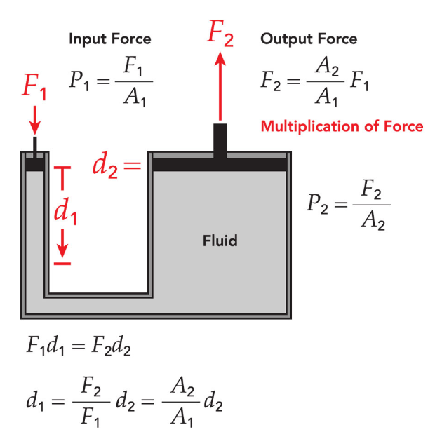
Pascal's Law forms the theoretical basis of hydraulics, stating that pressure applied to a confined fluid is transmitted undiminished in all directions. This principle enables hydraulic systems to multiply force and transmit power over considerable distances with minimal energy loss. The relationship between pressure, flow rate, and system geometry determines the overall performance characteristics of hydraulic applications.
Pascal's Law Formula
F₁/A₁ = F₂/A₂, where F is force and A is area
Schematic of Pascal's Law application in hydraulic systems
Viscosity Characteristics
Viscosity is one of the most important fluid properties affecting hydraulic system operation. The viscosity index indicates how fluid viscosity changes with temperature, directly impacting system efficiency under different operating conditions. Modern hydraulic systems require fluids that maintain consistent viscosity across a wide temperature range while providing adequate lubrication and corrosion protection.
Fluid Contamination Control
Fluid contamination remains a primary cause of hydraulic system failures. Particulate contamination causes component wear, reduces efficiency, and can lead to catastrophic system failure. Implementing proper filtration strategies and maintaining fluid cleanliness standards according to ISO 4406 classification ensures reliable system operation and extends component life.
Expert Tip
Hydraulic oil selection should consider operating temperature range, system pressure, environmental conditions, and expected service life. Generally, hydraulic oils with high viscosity indexes should be selected for high-temperature environments, while low-viscosity hydraulic oils are preferable in cold environments to ensure good fluidity.
2. Hydraulic Pumps & Motor Applications
Hydraulic pump serve as the heart of any hydraulic system, converting mechanical energy into hydraulic energy. Various pump technologies offer different advantages depending on application requirements. Gear pumps provide cost-effective solutions for applications requiring moderate pressure and flow, while piston pumps deliver high efficiency and precise control for demanding applications.
Gear Pumps
- Simple structure, low cost
- Easy maintenance, high reliability
- Relatively low pressure and efficiency
- Suitable for low to medium pressure systems
Vane Pumps
- Uniform flow, low noise
- Medium pressure range, good efficiency
- More sensitive to oil contamination
- Suitable for machine tools and automation
Piston Pumps
- High pressure capability, highest efficiency
- Variable displacement, flexible control
- Complex structure, higher cost
- Suitable for high-pressure heavy-duty applications
Variable Displacement Pump Technology
Variable displacement pumps offer exceptional flexibility by allowing flow rate adjustment without changing system pressure. This capability improves energy efficiency and provides precise control over actuator speed. Load-sensing pumps further enhance efficiency by automatically adjusting displacement based on system demand, reducing energy consumption and heat generation.
Hydraulic Motor Applications
Hydraulic motors convert hydraulic energy back into mechanical energy, providing rotational motion for various applications. The selection of gear motors, vane motors, or piston motors depends on factors such as torque requirements, speed range, efficiency needs, and cost considerations. Modern hydraulic motor designs incorporate advanced materials and manufacturing techniques to achieve higher efficiency and longer service life.
Pump and Motor Efficiency
Pump and motor efficiency significantly impact overall system performance and energy consumption. Volumetric efficiency relates to internal leakage, while mechanical efficiency accounts for frictional losses. Understanding these efficiency parameters enables engineers to select appropriate components and optimize system design for specific applications.
Overall efficiency, which is the product of volumetric and mechanical efficiency, is a key metric for evaluating hydraulic pump and motor performance. High-efficiency hydraulic pumps and motors can significantly reduce operating costs and reduce system heating.
3. Hydraulic Cylinder Design & Applications
Hydraulic cylinders are the most common actuators in hydraulic systems, converting hydraulic pressure into linear mechanical force and motion. Hydraulic cylinder design requires careful consideration of bore diameter, rod diameter, stroke length, and mounting configuration to meet specific application requirements.
Hydraulic Cylinder Types
Single-Acting Cylinders
Single-acting cylinders use hydraulic pressure for extension while relying on external force or gravity for retraction. This design features simple construction and lower cost, making it suitable for applications requiring only one direction of force.
Double-Acting Cylinders
Double-acting cylinders provide powered movement in both directions, offering better control and positioning accuracy. This design is widely used in applications requiring bidirectional force and precise control.
Telescopic Cylinders
Telescopic cylinders can achieve long strokes in compact installation spaces, making them ideal for mobile equipment applications. They consist of multiple nested sleeves that can extend to much greater lengths than their retracted size.
Schematic diagrams of various hydraulic cylinder structures
Sealing Systems
Hydraulic cylinder sealing systems prevent internal and external leakage while accommodating the dynamic movement requirements of pistons and piston rods. Modern sealing technologies utilize advanced materials and designs to minimize friction, reduce wear, and extend maintenance intervals. Proper seal selection considers factors such as pressure rating, temperature range, fluid compatibility, and expected service life.
Cushioning Systems
Cushioning systems integrated into hydraulic cylinder designs reduce impact loads and noise during end-of-stroke impacts. Adjustable cushions allow fine-tuning of deceleration curves to optimize cycle times while protecting system components from excessive stress.
Hydraulic Cylinder Design Calculations
Force Calculation
Extension force: F = P × A₁
Retraction force: F = P × (A₁ - A₂)
Where: P = working pressure, A₁ = piston area, A₂ = rod area
Speed Calculation
Extension speed: v = Q / A₁
Retraction speed: v = Q / (A₁ - A₂)
Where: Q = flow rate, A₁ = piston area, A₂ = rod area
4. Hydraulic Control Valve Systems
Hydraulic valve technology encompasses a wide range of components designed to control pressure, flow, and direction within hydraulic systems. Directional control valves manage flow paths, enabling precise control of actuator movement and positioning. These valves range from simple manually operated lever units to complex electro-hydraulic proportional valves with electronic feedback control.
Various valves in modern hydraulic control systems
Control Valve Classification
Directional Control Valves
Control the direction of hydraulic fluid flow, determining the direction of actuator movement. Includes check valves, directional valves, and manifold valves.
Pressure Control Valves
Control pressure within hydraulic systems, including relief valves, pressure reducing valves, sequence valves, and pressure switches.
Flow Control Valves
Regulate hydraulic fluid flow rate, controlling actuator movement speed, including throttle valves and flow control valves.
Pressure Control Valves
Pressure control valves maintain system safety and performance by regulating maximum system pressure and controlling pressure in specific circuit branches. Relief valves prevent overpressure conditions, while pressure-reducing valves maintain lower pressures for sensitive components or circuits requiring different operating pressures.
Flow Control Valves
Flow control valves regulate flow rate to control actuator speed and provide smooth, controlled movement. Pressure-compensated flow control valves maintain consistent flow despite system pressure changes, ensuring repeatable actuator performance under varying load conditions.
Proportional and Servo Valve Technology
Proportional valve and servo valve technologies enable precise, infinitely variable control of hydraulic parameters. These advanced valve systems integrate electronic control and feedback mechanisms to achieve the exceptional accuracy and response characteristics required for modern hydraulic servo systems and automated manufacturing equipment.
Technology Trends
Modern hydraulic control valves are evolving toward intelligent, integrated designs. Electro-hydraulic proportional control valves and digital control valves are becoming increasingly widespread, seamlessly integrating with industrial control systems to achieve higher precision control and more complex automation functions. Smart valves also feature self-diagnostic and condition monitoring capabilities, significantly improving system reliability and maintenance efficiency.
5. Hydraulic System Auxiliary Components
Hydraulic components beyond the main elements play crucial roles in system operation and reliability. Reservoirs store hydraulic oil, provide cooling capacity, and allow contaminants to settle out of the oil. Proper reservoir design includes adequate capacity, effective heat dissipation, and appropriate oil level monitoring systems.
Reservoirs
Store hydraulic oil, dissipate heat, separate air and contaminants from oil, provide stable oil supply to the system.
Filters
Remove contaminants from hydraulic oil, protect sensitive components, maintain system cleanliness, extend service life.
Coolers
Control hydraulic system temperature, dissipate heat generated during operation, maintain stable oil performance.
Accumulators
Store hydraulic energy, absorb pressure fluctuations, provide supplementary flow during peak demand, emergency power source.
Filtration Systems
Filtration systems remove contaminants from hydraulic oil, protecting sensitive components and maintaining system cleanliness. Return line filters capture particles generated during system operation, while pressure line filters protect sensitive components from contamination. Off-line filtration systems provide additional oil conditioning capabilities for critical applications.
Heat Exchangers
Heat exchangers manage system temperature by dissipating heat generated during normal operation. Air-cooled and water-cooled heat exchanger designs offer different advantages based on installation requirements and available cooling media. Proper temperature control extends component life and maintains consistent system performance.
Accumulators
Accumulators store hydraulic energy and provide supplementary flow during peak demand periods. These components also dampen pressure fluctuations, reduce pump cycling, and provide emergency power for critical functions in the event of pump failure.
Importance of Auxiliary Components
While primary components of hydraulic systems (pumps, valves, cylinders) typically receive more attention, auxiliary components are equally crucial to system performance and reliability. A well-designed auxiliary system can:
- Extend service life of primary components by 30-50%
- Improve system efficiency by 5-15%
- Significantly reduce failure rates and maintenance costs
- Enhance system performance and response characteristics
6. Basic Hydraulic Circuit Design
Basic hydraulic circuits combine individual components to create functional systems capable of performing specific tasks. Understanding fundamental circuit principles enables engineers to design efficient, reliable hydraulic systems tailored to application requirements.
Common Hydraulic Circuit Types
Regenerative Circuits
Regenerative circuits increase cylinder extension speed by directing return oil from the rod side to the cap side, effectively increasing available flow to the extending cylinder. This technique is particularly beneficial for applications requiring rapid extension with slower, high-force retraction capabilities.
Pilot Control Circuits
Pilot control circuits use small control valves and minimal pilot flow to achieve remote control of large valves. This approach reduces the size and cost of control components while maintaining full control authority over primary system functions.
Load Holding Circuits
Load holding circuits prevent uncontrolled movement of vertical loads when hydraulic power is removed. Counterbalance valves and pilot-operated check valves provide reliable load holding while allowing controlled lowering movement.
Hydraulic Circuit Design Principles
- Ensure adequate oil cleanliness to prevent contamination-induced failures
- Design appropriate pressure margins considering system pressure fluctuations
- Provide sufficient heat dissipation capacity to control oil temperature
- Include necessary safety devices such as relief valves and pressure switches
- Consider maintenance accessibility when designing component placement
Key Hydraulic Circuit Design Calculations
Pressure Calculation
System pressure should be determined based on load requirements, considering line losses and pressure margins (typically 10-20%).
Flow Calculation
Calculate flow requirements based on actuator speed and size requirements, ensuring pump and valve capacities match.
Line Sizing
Determine line sizes based on flow rate and allowable flow velocity, typically 0.5-1m/s for suction lines and 3-6m/s for pressure lines.
7. Industrial Hydraulic System Applications
Modern hydraulic systems serve a diverse range of industrial applications, each presenting unique challenges and requirements. Manufacturing automation relies heavily on hydraulic systems for stamping operations, material handling, and precision positioning tasks. These applications demand high reliability, precise control, and integration with electronic control systems.
Manufacturing Automation
In industries such as automotive manufacturing, metal processing, and plastic molding, hydraulic systems provide precise force control and reliable motion for stamping, bending, injection molding, and other processes.
Mobile Hydraulics
Power construction equipment, agricultural machinery, and material handling vehicles. These systems must operate reliably in harsh environments while delivering required power and control.
Aerospace Hydraulics
Operate under extreme conditions while maintaining exceptional reliability and performance standards. These systems employ redundant components and specialized materials.
Marine Hydraulics
Include steering systems, deck machinery, and propulsion control. Corrosive marine environments require specialized components and protection measures.
Mobile Hydraulic System Characteristics
Mobile hydraulic systems differ significantly from industrial hydraulic systems, primarily in:
- Power Source: Typically use internal combustion engines to drive hydraulic pumps rather than electric motors
- Environmental Adaptability: Must withstand dust, vibration, temperature changes, and other harsh conditions
- Space Constraints: Equipment size limitations require compact hydraulic component designs
- Energy Efficiency: Fuel efficiency is critical, affecting operating costs and environmental impact
High-Performance Hydraulic Application Trends
As technology advances, hydraulic system applications across various sectors are evolving toward:
- Intelligence: Integrating sensors and smart controls for condition monitoring and predictive maintenance
- Energy Efficiency: Adopting load-sensing systems, variable frequency drives, and other technologies to improve energy efficiency
- Integration: Closer integration with electrical and pneumatic systems to form hybrid power systems
- Environmental Friendliness: Using biodegradable hydraulic oils, reducing leakage risks, and minimizing environmental impact
8. Hydraulic System Design & Calculations
Systematic hydraulic system design begins with a comprehensive analysis of application requirements, including force and speed requirements, duty cycle characteristics, environmental conditions, and performance specifications. This analysis guides component selection and system architecture decisions.
Hydraulic System Design Process
Define Design Requirements
Clarify tasks the system needs to perform, load conditions, motion requirements, operating environment, safety standards, and performance metrics.
Conceptual Design
Develop preliminary system方案, select basic circuit structures, determine actuator types and quantities, and plan power source configurations.
Detailed Calculations
Perform calculations for force, speed, flow, pressure, power, and other parameters to determine component specifications and sizes.
Component Selection
Select appropriate pumps, valves, cylinders, motors, and other components based on calculation results, ensuring performance matching and compatibility.
System Integration & Optimization
Complete system layout design, perform pipeline calculations, consider heat dissipation, filtration, safety, and other factors, and optimize system performance.
Flow Calculations
Flow calculations determine required pump capacity, pipe sizing, and valve flow ratings. For hydraulic cylinders, flow relates to velocity and effective area:
Q = v × A
Where: Q = flow rate (m³/s), v = velocity (m/s), A = effective area (m²)
Pressure Calculations
Pressure calculations ensure adequate system pressure while maintaining safety margins and optimizing energy efficiency:
P = F / A + ΔP
Where: P = required pressure (Pa), F = load force (N), A = area (m²), ΔP = pressure loss (Pa)
Heat Calculations
Heat generation calculations guide heat exchanger sizing and reservoir capacity requirements:
Q = P × (1 - η)
Where: Q = heat (W), P = input power (W), η = system efficiency
Component Sizing Determination
Component sizing procedures consider factors such as safety factors, efficiency characteristics, and expected service life requirements. Proper sizing ensures reliable operation while avoiding over-specification that increases system cost and complexity.
System Simulation Software
System simulation software enables engineers to model hydraulic system behavior under various operating conditions. These tools help optimize system design, component selection, and control strategies before physical implementation.
Design Best Practices
Key principles to follow in hydraulic system design:
- Adopt modular design for ease of maintenance and upgrades
- Consider appropriate safety factors (typically 1.5-2 times)
- Ensure compatibility between system components
- Consider energy consumption and operating costs during design
- Include necessary safety devices and emergency measures
9. Advanced Hydraulic Servo Systems
Hydraulic servo systems provide exceptional precision and response characteristics for demanding applications requiring precise position, velocity, or force control. These systems integrate high-performance servo valves, precision actuators, and sophisticated electronic control systems to achieve superior dynamic performance.
Schematic of closed-loop control principle in hydraulic servo systems
Closed-Loop Control Systems
Closed-loop control systems integrate position, velocity, or pressure feedback to maintain precise control over system parameters. Advanced control algorithms compensate for system nonlinearities, external disturbances, and component variations to maintain consistent performance.
Servo Valve Technology
Servo valve technology enables fast, precise control of hydraulic flow and pressure. These valves utilize advanced materials, precision manufacturing, and innovative designs to achieve the response characteristics and accuracy required for servo applications.
Digital Control Systems
Digital control systems offer flexibility and advanced functionality compared to analog control methods. Digital controllers implement complex control strategies, adaptive algorithms, and integration with plant-wide control systems.
Key Performance Indicators for Hydraulic Servo Systems
-
Response Time
Time for system to reach specified state after receiving command
-
Positioning Accuracy
Deviation between actual position and commanded position
-
Stability
System's ability to return to stable state after disturbance
-
Bandwidth
Highest frequency signal the system can respond to
Advanced Hydraulic Servo System Applications
-
Precision Manufacturing
CNC machine tools, precision presses, electronic component manufacturing equipment
-
Aerospace
Flight simulators, wind tunnel test equipment, satellite positioning systems
-
Test Equipment
Material testing machines, structural dynamic test systems, vibration tables
-
Medical Equipment
Precision surgical robots, radiation therapy equipment
Advantages of Hydraulic Servo Systems
High Precision Control
Capable of micron-level position control and precise force control
Fast Response
Millisecond response speed, suitable for dynamic control applications
High Power Density
Compact size but capable of high force and torque output
Strong Anti-interference
Strong resistance to external disturbances, good stability
10. Pneumatic Transmission Systems
Pneumatic systems utilize compressed air as the working medium, offering advantages of cleanliness, safety, and simple control. Pneumatic-hydraulic systems represent a hybrid approach, utilizing pneumatic power for certain functions while maintaining hydraulic power for high-force applications.
Air Supply Treatment Systems
Air supply treatment systems condition compressed air by removing moisture, oil, and contaminants while regulating pressure to appropriate levels. Proper air supply treatment ensures reliable component operation and extends the service life of pneumatic elements.
Typical Air Supply Treatment Unit Components
- Air filters: Remove solid particles and moisture
- Dryers: Further remove moisture from air
- Oil mist separators: Remove oil contaminants
- Pressure regulators: Adjust pressure to system requirements
Pneumatic Control Technology
Control valve technology for pneumatic systems ranges from simple manual valves to complex electro-pneumatic proportional valves. These components enable precise control over actuator movement and system response characteristics.
Pneumatic Actuators
Pneumatic actuators convert compressed air energy into mechanical motion. Cylinders provide linear motion, while pneumatic motors generate rotational movement. These actuators feature fast response and simple control, making them ideal for automation applications.
Pneumatic vs. Hydraulic Systems
Pneumatic systems are typically used for applications requiring fast movement, medium force output, and clean environments, while hydraulic systems are suitable for applications requiring high force output, precise control, and heavy load capabilities. Pneumatic systems use compressed air, which is easy to obtain and handle, while hydraulic systems require specialized hydraulic oil and more complex maintenance.
Pneumatic System Application Areas
Automated Production Lines
Used for part handling, sorting, clamping, and positioning, providing fast response and reliable action.
Packaging Machinery
Used in food, pharmaceutical, and consumer goods packaging for gripping, sealing, and forming operations.
Medical Equipment
Provide precise, clean power in dental equipment, respiratory devices, and surgical tools.
Logistics & Warehousing
Used in conveyor systems, sorting systems, and automated storage equipment control.
Textile Industry
Control tension and position in textile machinery to ensure production quality.
Automotive Manufacturing
Used in assembly lines for robotic operations, welding fixtures, and material handling.
11. Installation & Commissioning
Proper installation procedures ensure hydraulic and pneumatic systems achieve design performance and reliability standards. System cleanliness during installation prevents contamination that could compromise component performance and service life.
Pre-Installation Preparation
- Ensure installation area is clean, dry, and has sufficient space
- Inspect all components for damage and conformity to specifications
- Prepare necessary tools and testing equipment
- Develop detailed installation plans and procedures
Hydraulic Piping Installation
Hydraulic piping installation must consider factors such as pressure loss, flow velocity, and thermal expansion. Proper pipe sizing and routing minimize energy losses and reduce system noise levels.
Hydraulic Hose Installation
Hydraulic hose maintenance and installation require specialized techniques and tools to ensure reliable connections and proper routing. Proper hose selection considers pressure rating, temperature range, fluid compatibility, and routing requirements.
Seal Installation
Hydraulic seal installation requires special attention to seal orientation, lubrication, and protection during assembly to prevent damage. Proper installation techniques prevent premature seal failure and ensure reliable system operation.
Commissioning Procedures
Commissioning procedures verify system performance against design specifications and identify any installation issues requiring correction. System testing ensures all safety systems function properly and system performance meets application requirements.
Installation & Commissioning Checklist
Installation Checks
- All components installed securely according to manufacturer recommendations
- Piping routed properly, avoiding excessive bending and twisting
- All connections properly tightened with no leaks
- System cleanliness meets requirements and flushing has been performed
- Electrical connections correct with good grounding
Commissioning Checks
- System pressure within design range and stable with no fluctuations
- Actuator movement smooth with speed meeting requirements
- System temperature within normal range with no abnormal heating
- All safety devices functioning properly
- System noise level within acceptable range
12. Troubleshooting & Maintenance Strategies
Effective hydraulic system maintenance programs integrate preventive, predictive, and corrective maintenance strategies to optimize system availability and minimize total cost of ownership. Understanding common failure modes and their symptoms enables rapid diagnosis and resolution of system issues.
Preventive Maintenance
Maintenance activities performed at predetermined intervals to prevent failures, including regular inspections, oil changes, and filter replacements.
Predictive Maintenance
Maintenance based on actual system condition, predicting potential failures through monitoring of key parameters and performing maintenance at appropriate times.
Corrective Maintenance
Maintenance activities performed after system failure, aiming to repair faults and restore system functionality.
Oil Analysis Programs
Oil analysis programs monitor hydraulic oil condition and contamination levels, providing early warning of potential issues. Regular oil sampling and analysis enable proactive maintenance interventions before component damage occurs.
Performance Monitoring Systems
Performance monitoring systems track key system parameters such as pressure, flow, temperature, and vibration levels. Trending these parameters over time can identify potential issues and enable planned maintenance interventions.
International Standards
International hydraulic standards provide guidelines for system design, installation, maintenance, and safety procedures. Adherence to these standards ensures systems meet performance and safety requirements while promoting global interchangeability of components and systems.
Common Faults and Diagnostic Methods
Pressure Abnormalities
Possible causes: Pump failure, relief valve malfunction, pipe blockage or leakage Diagnostic methods: Pressure testing, component isolation checks, oil analysis
Actuator Movement Abnormalities
Possible causes: Control valve failure, seal damage, oil contamination Diagnostic methods: Flow testing, visual inspection, component replacement testing
System Overheating
Possible causes: Cooling system failure, insufficient oil, low component efficiency Diagnostic methods: Temperature monitoring, thermal imaging, efficiency testing
Abnormal Noise
Possible causes: Pump cavitation, component wear, pipe vibration Diagnostic methods: Auditory inspection, vibration analysis, oil analysis
Maintenance Best Practices
When implementing effective hydraulic system maintenance programs, consider these key practices:
- Maintain detailed maintenance records, including all inspections, repairs, and replacements
- Perform regular oil analysis rather than just changing oil on a time-based schedule
- Train maintenance personnel to recognize early failure signs and proper maintenance procedures
- Keep systems clean, including reservoirs, filters, and surrounding environment
- Adopt condition-based maintenance strategies combining predictive and preventive approaches
The field of hydraulics continues to evolve with advances in technology, environmental requirements, and application needs. Modern hydraulic and pneumatic transmission systems provide exceptional power transmission capabilities, precise control, and reliable operation across a wide range of applications.
Successful implementation of hydraulic systems requires a comprehensive understanding of fundamental principles, component technologies, system design methods, and maintenance practices. The integration of electronic controls, advanced materials, and innovative design approaches continues to expand the capabilities and applications of fluid power systems.
Future developments in hydraulic technology will likely focus on improving energy efficiency, environmental sustainability, and integration with digital control systems. These advancements will further enhance the versatility and performance of hydraulic and pneumatic transmission systems, ensuring their continued importance in modern industrial applications.
Engineers and technicians working with fluid power systems must stay current with technological developments, industry standards, and best practices to design, implement, and maintain systems that meet evolving application requirements while achieving optimal performance and reliability.