
Hydraulic systems play a critical role in countless industrial applications, from heavy machinery to precision manufacturing. This comprehensive guide explores the fundamental properties of hydraulic fluids, their classifications, contamination control measures, and advanced design considerations that engineers and technicians need to understand for optimal system performance.
"The performance and reliability of any hydraulic system ultimately depend on a thorough understanding of the physical properties of hydraulic fluids and how they interact with system components under various operating conditions."
Section 1: Physical Properties of Hydraulic Fluids
Density of Hydraulic Fluids
The fundamental definition for hydraulic fluid density refers to the mass of liquid per unit volume, commonly denoted as ρ (kg/m³). This essential property can be expressed mathematically as:
ρ = m/V (Equation 2-1)
Where:
- V represents the volume of the liquid (m³)
- m represents the mass of the liquid (kg)

Density stands as one of the most critical physical parameters in hydraulic systems. While the density value experiences slight variations with changes in temperature or pressure, these fluctuations remain minimal enough to be negligible in most practical applications. Common hydraulic oils typically maintain a density of approximately 900 kg/m³, making them ideal for various industrial applications.
Compressibility Characteristics of Hydraulic Fluids
The compressibility of liquids represents their ability to decrease in volume when subjected to pressure. This property plays a crucial role in understanding the definition for hydraulic system behavior. When a liquid with volume V experiences a pressure increase of Δp, resulting in a volume decrease of ΔV, the relative volume change per unit pressure can be expressed as:
k = -(1/Δp) · (ΔV/V) (Equation 2-2)
Where k represents the volume compression coefficient of the liquid. The negative sign ensures that k remains positive, as pressure increases always correspond to volume decreases, making Δp and ΔV consistently opposite in sign.
The reciprocal of k defines the bulk modulus of the liquid, denoted as K:
K = 1/k = -VΔp/ΔV (Equation 2-3)
The bulk modulus K indicates the pressure increment required to produce a unit relative volume change in the liquid. Under normal temperature conditions, pure hydraulic oil exhibits a bulk modulus K ranging from 1.4×10⁹ to 2.0×10⁹ Pa. This remarkably high value allows hydraulic oil to be considered virtually incompressible for most practical purposes.
However, when air becomes mixed with hydraulic oil, the compression resistance capability decreases significantly, severely impacting the hydraulic system's performance.
Bulk Modulus Comparison: Pure Oil vs. Aerated Oil
Therefore, when considering hydraulic oil compressibility, engineers must comprehensively account for multiple factors: the inherent compressibility of the hydraulic oil itself, the compressibility of any entrained air bubbles, and the volumetric deformation of the sealed containers and pipelines containing the hydraulic oil. These combined effects are typically represented by an equivalent bulk modulus K', which ranges from 0.7×10⁹ to 1.4×10⁹ Pa.
Under variable pressure conditions, the compressibility of hydraulic oil behaves similarly to a mechanical spring. As pressure increases, the oil volume contracts; conversely, as pressure decreases, the oil volume expands. When an external force acting on a confined liquid changes by ΔF, if the liquid's pressure-bearing area A remains constant, the liquid column length must change by Δl. This relationship can be expressed through:
Volume change: ΔV = AΔl
Pressure change: Δp = ΔF/A
Pressure change: Δp = ΔF/A
Leading to:
K = -VΔF/(A²Δl)
Or alternatively:
Kh = -ΔF/Δl = -ΔpA/Δl = (A²/V)K (Equation 2-4)
Where Kh represents the stiffness of the hydraulic spring, a crucial parameter in system design.
Viscosity Properties of Hydraulic Fluids
Understanding Viscosity Significance
Viscosity represents a fundamental property in the definition for hydraulic fluid behavior. When liquids flow under external forces, intermolecular cohesive forces resist the relative motion between molecules, creating internal friction. This property, known as viscosity, serves as one of the most important physical characteristics of hydraulic fluids and forms the primary criterion for hydraulic oil selection.
During liquid flow, the adhesive forces between liquid and solid surfaces, combined with the liquid's inherent viscosity, create velocity gradients across different fluid layers. Consider two parallel plates with liquid filling the gap between them. When the lower plate remains stationary while the upper plate moves rightward at velocity u₀, viscous effects cause the liquid layer adhering to the lower plate surface to have zero velocity, while the layer adhering to the upper plate surface moves at velocity u₀.
Experimental evidence demonstrates that the internal friction force Ff between adjacent flowing liquid layers is proportional to both the contact area A and the velocity gradient du/dy:
Ff = μA(du/dy) (Equation 2-5)
Where μ represents the proportionality coefficient, known as dynamic viscosity.
If τ denotes the internal friction force per unit area between liquid layers, then:
τ = μ(du/dy) (Equation 2-6)
This equation represents Newton's law of internal friction for liquids, fundamental to understanding hydraulic system behavior.
Types of Viscosity Measurements
Viscosity magnitude is expressed through three common measurement types: dynamic viscosity, kinematic viscosity, and relative viscosity, each serving specific purposes in hydraulic system design.
Dynamic Viscosity (μ)
Also termed absolute viscosity, derived from Newton's law of internal friction. Represents the internal friction force per unit area between flowing liquid layers with unit velocity gradient. Units: N·s/m² or Pa·s.
Kinematic Viscosity (ν)
Equals the ratio of dynamic viscosity to liquid density (ν = μ/ρ). Units: m²/s, with common industrial unit cSt (mm²/s). Hydraulic oil grades are typically designated by kinematic viscosity at 40°C.
Relative Viscosity
Also called conditional viscosity, measured using specific viscometers under prescribed conditions. Examples include Engler, Saybolt, and Redwood viscosity scales used in different countries.
(3) Relative Viscosity
Relative viscosity, also called conditional viscosity, represents viscosity measured using specific viscometers under prescribed conditions. Different countries employ various relative viscosity standards due to varying measurement conditions. China, Germany, and Russia utilize Engler viscosity, while the United States uses Saybolt viscosity, and the United Kingdom employs Redwood viscosity.
Engler viscosity measurements involve placing 200 mL of test liquid in an Engler viscometer. At a specific temperature, the time t₁ required for the liquid to flow completely through a φ2.8 mm orifice at the container bottom is measured and compared to the time t₂ required for the same volume of distilled water at 20°C to flow through the same orifice (typically t₂ = 52 s). This ratio provides the Engler viscosity at that temperature:
°E = t₁/t₂ (Equation 2-8)
The conversion relationship between Engler viscosity and kinematic viscosity ν (mm²/s) follows:
ν = 7.31°E - 6.31/°E
(4) Blended Oil Viscosity (Engler Viscosity)
Selecting appropriate viscosity hydraulic oil significantly impacts hydraulic system performance. When available hydraulic oils don't meet viscosity requirements, two oils with different viscosities can be mixed in appropriate proportions to create blended oil. The definition for hydraulic blended oil viscosity can be calculated using the empirical formula:
°E = (a°E₁ + b°E₂ - c(°E₁ - °E₂))/100 (Equation 2-10)
Where:
- °E₁, °E₂ represent Engler viscosities of the two oils before mixing (°E₁ > °E₂)
- °E represents the blended oil's Engler viscosity
- a, b are coefficients for the two participating oils
- c is an experimental coefficient (values shown in Table 2-1)
| a | 10 | 20 | 30 | 40 | 50 | 60 | 70 | 80 | 90 |
|---|---|---|---|---|---|---|---|---|---|
| b | 90 | 80 | 70 | 60 | 50 | 40 | 30 | 20 | 10 |
| c | 6.7 | 13.1 | 17.9 | 22.1 | 25.5 | 27.9 | 28.2 | 25 | 17 |
Viscosity-Pressure Relationship
When liquid experiences increased pressure, intermolecular distances decrease, internal friction increases, and viscosity rises accordingly. For typical hydraulic systems operating below 20 MPa, pressure effects on viscosity remain negligible. However, at higher pressures or when pressure varies significantly, viscosity changes become considerable. The viscosity-pressure relationship for petroleum-based hydraulic oils follows:
νₚ = νₚ₀(1 + 0.003p) (Equation 2-11)
Where νₚ and νₚ₀ represent kinematic viscosities at pressure p and relative pressure 0, respectively.
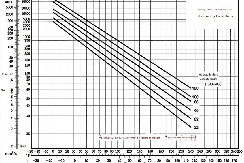
Viscosity-Temperature Relationship
Oil viscosity demonstrates extreme sensitivity to temperature changes. Rising temperatures cause significant viscosity decreases. This property of viscosity variation with temperature, termed viscosity-temperature characteristics, varies among different hydraulic oil types. Oils with superior viscosity-temperature characteristics show minimal viscosity changes with temperature fluctuations, reducing temperature effects on hydraulic system performance.
Viscosity-Temperature Relationship for Different Hydraulic Oils
The dynamic viscosity-temperature relationship for hydraulic oils can be expressed as:
μₜ = μₜ₀e^(-λ(t - t₀)) ≈ μₜ₀(1 - λΔt) (Equation 2-12)
Where:
- μ₀, μₜ represent dynamic viscosities at temperatures t₀ and t
- λ represents a coefficient value
Viscosity-temperature characteristics are quantified using the Viscosity Index (VI). Higher VI values indicate smaller viscosity change rates with temperature, representing superior viscosity-temperature characteristics. General hydraulic oils require VI values exceeding 90, while refined hydraulic oils with additives can achieve VI values above 100.
Section 2: Types and Selection of Hydraulic Oils
Performance Requirements for Hydraulic Oils
The definition for hydraulic oil performance encompasses multiple critical requirements that ensure optimal system operation:
Superior Viscosity-Temperature Characteristics
Within operating temperature ranges, oil viscosity changes with temperature must remain minimal to maintain consistent system performance.
Excellent Lubrication Properties
Since hydraulic oil serves dual roles as both working medium and lubricant for moving components, superior lubrication characteristics are essential for system longevity.
Chemical Stability
Oils must resist oxidation effectively. Oxidized oils produce gummy deposits and tar-like substances that can obstruct hydraulic components, leading to system failures.
Purity and Anti-Foaming Properties
Hydraulic oils must remain free from corrosive substances that could damage components and sealing devices. Effective anti-foaming properties prevent air entrainment issues.
High Flash Point and Low Pour Point
These thermal properties ensure safe operation across wide temperature ranges, preventing fire hazards while maintaining fluidity at low temperatures.
Categories of Hydraulic Oils
Hydraulic oils encompass three primary categories: petroleum-based, synthetic, and emulsion types. Table 2-2 presents the main varieties and their properties.
| Category | Properties | Combustible Hydraulic Oils | Fire-Resistant Hydraulic Oils | |||
|---|---|---|---|---|---|---|
| Petroleum-Based | Synthetic | Emulsion | Water-Glycol | Others | ||
| Characteristics | Density ρ/(kg·m⁻³) | 850-900 | 1100-1500 | 1040-1100 | 920-940 | 1000 |
| Viscosity | Low-High | Low-High | Low-High | Low-High | Very Low | |
| Viscosity Index VI ≥ | 90 | 95 | 130 | 130-180 | 140-170 | |
| Lubrication | Excellent | Excellent | Excellent | Good | Fair | |
| Corrosion Protection | Excellent | Excellent | Good | Good | Fair | |
| Flash Point ≥/°C | 170-200 | 170 | 150-170 | Non-flammable | Non-combustible | |
| Pour Point ≤/°C | -10 | -25 | -45 to -35 | -50 to -20 | -5 | |
Petroleum-based hydraulic oils derive from total loss system oils (formerly mechanical oils) as base stock, refined and enhanced with appropriate additives. These oils provide excellent lubrication but poor fire resistance. Currently, many hydraulic transmission systems still commonly use total loss system oils and turbine oils.
Despite numerous advantages, petroleum-based hydraulic oils' main disadvantage involves flammability. In high-temperature, flammable, or explosive environments, safety considerations mandate using fire-resistant fluids.
Hydraulic Oil Selection Criteria
The selection process begins with choosing appropriate hydraulic oil types based on system environment and working conditions, followed by grade selection. The definition for hydraulic oil grade selection primarily involves viscosity grade determination, as viscosity significantly impacts system stability, reliability, efficiency, temperature rise, and wear characteristics.
Key viscosity selection considerations include:
System Working Pressure
High-pressure hydraulic systems benefit from higher viscosity oils for improved sealing and reduced leakage. Conversely, lower-pressure systems can utilize lower viscosity oils effectively.
Environmental Temperature
Higher ambient temperatures require higher viscosity oils to compensate for temperature-induced viscosity reduction effects.
Movement Speed
Higher component movement speeds warrant lower viscosity oils to minimize flow friction losses and improve system responsiveness.
Among all hydraulic system components, pumps demonstrate greatest sensitivity to hydraulic oil properties due to highest internal movement speeds, maximum pressure loads, extended pressure duration, and elevated temperatures. Therefore, viscosity selection often depends on pump type and requirements. Table 2-3 presents applicable viscosity ranges for various pump types.
| Pump Type | Environmental Temperature (°C) | Viscosity at 40°C (mm²/s) | Viscosity at 50°C (mm²/s) |
|---|---|---|---|
| Gear Pumps | -5 to 40 | 30-70 | 17-40 |
| Below -5 | 54-110 | 58-98 | |
| Vane Pumps | |||
| p < 7 MPa, 5-40 | 30-50 | 17-29 | |
| p < 7 MPa, Below 5 | 43-77 | 25-44 | |
| p ≥ 7 MPa, 5-40 | 54-70 | 31-40 | |
| p ≥ 7 MPa, Below 5 | 65-95 | 35-55 | |
| Piston Pumps | |||
| Axial Type, 10-40 | 43-77 | 25-44 | |
| Axial Type, Below 10 | 70-172 | 40-98 | |
| Radial Type, 0-40 | 30-128 | 17-62 | |
| Radial Type, Below 0 | 65-270 | 37-154 |
Section 3: Hydraulic Oil Contamination and Control
Contamination Hazards
Understanding the definition for hydraulic oil contamination is crucial for system maintenance. Contamination refers to the presence of water, air, microscopic solid particles, and gelatinous formations within hydraulic oil. System failures frequently stem from oil contamination, making contamination control paramount.

Contamination creates three primary hazard categories:
- Component Blockage and Malfunction: Solid particles and gelatinous formations obstruct filters, causing pump cavitation and noise generation.
- Accelerated Wear and Leakage: Microscopic solid particles accelerate component wear, compromising hydraulic element functionality.
- System Performance Degradation: Water and air contamination reduces lubricating capability while promoting oxidation and deterioration.
Contamination Sources
Hydraulic oil contamination originates from three primary sources, each requiring specific control strategies:
Residual Contamination
Sand particles, metal chips, grinding debris, welding slag, rust flakes, oil sludge, cotton fibers, and dust introduced during manufacturing, storage, transportation, installation, and maintenance processes.
Environmental Intrusion
Surrounding environmental pollutants including air, dust particles, and water droplets penetrate systems through various entry points like piston rod seals and tank breather vents.
Internal Generation
Metal particles from component wear, seal material degradation, paint flaking, moisture accumulation, air bubble formation, and gelatinous oxidation products generated during operation.
Contamination Control Strategies
The complex nature of hydraulic oil contamination, combined with continuous internal contaminant generation, makes complete elimination impossible. However, maintaining contamination within acceptable limits ensures extended component life and reliable system operation. The definition for hydraulic contamination control involves implementing comprehensive strategies:
Eliminating Residual Contamination
Hydraulic assemblies require thorough cleaning before and after assembly. Component cleanliness standards must meet or exceed system requirements through systematic cleaning procedures.
Minimizing External Contamination
Tank atmospheric connections require air filtration systems. Oil filling operations must utilize appropriate filters. Component maintenance and disassembly should occur in controlled, dust-free environments.
Filtering System-Generated Contaminants
Strategic placement of appropriate-grade filters throughout the system captures internally generated particles. Regular filter inspection, cleaning, and replacement schedules maintain filtration effectiveness.
Scheduled Oil Inspection and Replacement
Following equipment manufacturer specifications and maintenance procedures, regular oil inspection and replacement prevents contamination accumulation. Oil changes require complete tank cleaning and comprehensive system flushing.

Advanced Considerations in Hydraulic System Design
Temperature Effects on System Performance
The relationship between temperature and hydraulic oil properties significantly influences system design considerations. The definition for hydraulic system efficiency directly correlates with maintaining optimal operating temperatures. Engineers must account for viscosity variations across expected temperature ranges when specifying components and designing cooling systems.
Temperature management strategies include:
- Heat Exchanger Selection: Properly sized heat exchangers maintain oil temperatures within optimal ranges, preserving viscosity characteristics and preventing thermal degradation.
- Reservoir Design: Adequate reservoir capacity provides thermal mass for temperature stabilization while allowing sufficient residence time for air separation and contaminant settling.
- Component Placement: Strategic component arrangement minimizes heat generation concentration while promoting natural convection cooling patterns.
Pressure Considerations in Modern Systems
Contemporary hydraulic systems operate at increasingly higher pressures, demanding careful consideration of fluid properties under extreme conditions. The definition for hydraulic system pressure ratings must account for viscosity changes, compressibility effects, and component stress factors.
High-pressure system design requirements include:
Enhanced Filtration
Higher pressures accelerate wear rates, necessitating superior filtration to maintain oil cleanliness and protect sensitive components.
Specialized Fluids
Extreme pressure applications may require synthetic fluids or specialized additives to maintain lubrication film integrity under severe conditions.
Component Selection
Pumps, valves, and actuators must withstand pressure spikes and fatigue loading while maintaining acceptable internal leakage rates.
Environmental and Safety Considerations
Modern hydraulic system design increasingly emphasizes environmental protection and operational safety. The definition for hydraulic fluid environmental compatibility encompasses biodegradability, toxicity, and disposal considerations.
Environmental protection measures
- Biodegradable Fluids: Environmentally sensitive applications utilize biodegradable hydraulic fluids that minimize ecological impact from leakage or spills.
- Leak Prevention: Enhanced sealing technologies and monitoring systems prevent fluid loss, protecting both environment and reducing operating costs.
- Proper Disposal: Used hydraulic oil requires appropriate recycling or disposal following environmental regulations, preventing soil and water contamination.
Safety considerations
- Fire-Resistant Fluids: Applications near ignition sources mandate fire-resistant hydraulic fluids, including water-based fluids or synthetic phosphate esters.
- System Monitoring: Pressure, temperature, and contamination monitoring systems provide early warning of potential failures, preventing catastrophic events.
- Emergency Shutdown: Fail-safe designs incorporate emergency shutdown capabilities, protecting personnel and equipment during system malfunctions.
Future Developments in Hydraulic Technology
Advancing technology continues expanding the definition for hydraulic system capabilities through innovative fluid formulations and system designs. Emerging trends include:
Smart Fluids
Magnetorheological and electrorheological fluids offer variable viscosity properties, enabling adaptive system responses to changing conditions. These fluids can change their viscosity almost instantaneously when exposed to magnetic or electric fields, allowing for precise control and energy efficiency.
Nanotechnology Applications
Nanoparticle additives enhance lubrication properties, reduce wear rates, and improve thermal conductivity in advanced hydraulic fluids. These engineered nanoparticles can fill micro-cracks in surfaces, providing self-healing properties and extending component life.
Condition Monitoring
Real-time fluid analysis systems detect contamination, oxidation, and additive depletion, enabling predictive maintenance strategies. These smart monitoring systems can identify potential issues before they cause system failures, significantly reducing downtime and maintenance costs.
Energy Efficiency
Improved fluid formulations reduce internal friction losses while maintaining protection properties, increasing overall system efficiency. Combined with advanced component designs, these fluids contribute to more sustainable hydraulic systems with reduced energy consumption.
Maintenance Best Practices
Effective maintenance programs ensure optimal hydraulic system performance throughout equipment lifecycles. The definition for hydraulic maintenance excellence involves systematic approaches to fluid management, contamination control, and component care.
Fluid Analysis Programs
Regular oil sampling and analysis detect developing problems before failures occur, optimizing maintenance intervals and reducing downtime. Comprehensive analysis includes checking for contamination levels, oxidation, additive depletion, and wear particles.
Filtration Management
Multi-stage filtration strategies remove contaminants at generation sources while protecting sensitive components from damage. Regular filter inspection and replacement, combined with proper filter sizing, ensure effective contamination control throughout the system.
System Integration and Optimization
Modern hydraulic systems require holistic design approaches integrating mechanical, electrical, and control elements. The definition for hydraulic system integration encompasses component selection, control strategies, and performance optimization.
Electronic Controls
Proportional and servo valves enable precise motion control, improving accuracy and repeatability in demanding applications. These electronic controls allow for complex motion profiles and adaptive system responses.
Sensor Integration
Pressure, flow, and position sensors provide feedback for closed-loop control, enhancing system performance and efficiency. Real-time data from these sensors enables condition monitoring and predictive maintenance.
Simulation Tools
Computer modeling and simulation optimize system designs before implementation, reducing development time and costs. Advanced simulation software can predict system behavior under various operating conditions.
Understanding the comprehensive definition for hydraulic systems requires thorough knowledge of fluid properties, contamination control, and system design principles. From fundamental viscosity concepts to advanced contamination management strategies, each aspect contributes to reliable, efficient hydraulic system operation.
Successful hydraulic system implementation demands careful attention to fluid selection, matching oil properties to application requirements. Temperature and pressure effects on viscosity must be considered alongside contamination control measures to ensure long-term reliability.
Future developments in hydraulic technology promise enhanced capabilities through smart fluids, advanced monitoring systems, and improved environmental compatibility. However, fundamental principles of fluid mechanics, proper maintenance, and contamination control remain cornerstone requirements for hydraulic system success.
Engineers and technicians must maintain current knowledge of evolving hydraulic technologies while mastering established principles. This balanced approach ensures optimal system design, implementation, and maintenance, maximizing equipment reliability and operational efficiency.
The definition for hydraulic excellence encompasses not merely understanding individual components but appreciating complex interactions between fluids, components, and operating conditions. Through comprehensive knowledge application and systematic maintenance approaches, hydraulic systems continue providing reliable power transmission and control solutions across diverse industrial applications.
As technology advances and environmental considerations gain prominence, hydraulic system design will continue evolving. However, fundamental physical principles governing fluid behavior remain unchanged, providing the foundation for future innovations in hydraulic technology. Understanding these principles, combined with practical application experience, enables engineers to design and maintain hydraulic systems that meet increasingly demanding performance requirements while minimizing environmental impact and maximizing operational safety.