
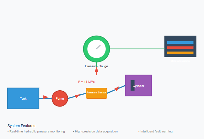
The hydraulic pressure gauge serves as a fundamental instrument in hydraulic transmission systems, providing critical real-time monitoring of system pressure conditions. In modern hydraulic systems, understanding pressure dynamics and utilizing appropriate measurement tools has become essential for maintaining system efficiency and preventing catastrophic failures. The proper selection and installation of a hydraulic pressure gauge can mean the difference between smooth operation and costly equipment damage.
Hydraulic systems operate under varying pressure conditions that require continuous monitoring to ensure optimal performance. A well-calibrated hydraulic pressure gauge not only displays current pressure readings but also helps operators identify potential issues before they escalate into major problems. These instruments have evolved significantly over the years, from simple mechanical devices to sophisticated digital systems capable of data logging and remote monitoring.
In hydraulic transmission systems, hydraulic shock and cavitation phenomena can adversely affect normal system operation. Understanding these phenomena is crucial for proper hydraulic pressure gauge selection and system design. Therefore, it is necessary to understand the causes of these phenomena and take measures to prevent and control them.
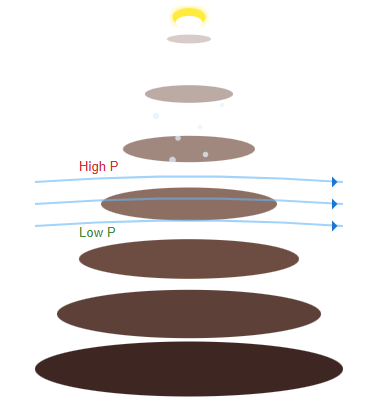
Hydraulic shock occurs when system pressure suddenly and dramatically increases at a particular moment, forming very high pressure peaks. This phenomenon poses significant challenges for accurate pressure measurement, as a standard hydraulic pressure gauge may not be designed to withstand such extreme transient pressures. In hydraulic systems, the pressure at a certain instant may suddenly rise sharply due to various reasons, creating pressure peaks that can damage sensitive measurement equipment.
When valves suddenly close or hydraulic cylinders undergo rapid braking, liquid flow in the system is suddenly obstructed. At this time, due to the inertial effect of the liquid flow, the liquid begins from the obstructed end and rapidly converts kinetic energy into pressure energy layer by layer, thus generating pressure shock waves. These shock waves can severely damage an unprotected hydraulic pressure gauge if proper dampening mechanisms are not in place.
Subsequently, starting from the other end, pressure energy is converted back into kinetic energy layer by layer, and the liquid flows in reverse. This process repeats, continuously converting between kinetic and pressure energy. This rapid back-and-forth propagation of pressure waves creates pressure oscillations within the system.
Pressure spikes recorded by a hydraulic pressure gauge during system shock events
When hydraulic shock occurs in a system, the instantaneous pressure peak can be several times higher than normal working pressure. Without proper protection, a hydraulic pressure gauge exposed to such conditions may suffer permanent damage or provide inaccurate readings. Hydraulic shock can damage sealing devices, pipelines, or hydraulic components, and can also cause equipment vibration and generate significant noise. Sometimes, hydraulic shock can cause certain hydraulic components (such as pressure relays and sequence valves) to malfunction, affecting normal system operation.
The selection of an appropriate hydraulic pressure gauge requires understanding the maximum pressures that may occur during shock conditions. Assuming the normal working pressure of the system is p, the maximum pressure when hydraulic shock occurs, that is, the peak pressure of the first wave of the pressure shock wave is:
pmax = p + Δp (Equation 2-45)
Where Δp represents the maximum increase in shock pressure.
Since hydraulic shock involves unsteady flow with very complex dynamic processes and many influencing factors, accurately calculating the Δp value is quite difficult. For proper hydraulic pressure gauge selection, engineers must consider these potential pressure spikes. The following presents approximate calculation formulas for Δp values under two types of hydraulic shock conditions.
When designing systems with a hydraulic pressure gauge, understanding pipeline dynamics is crucial. Consider a pipeline with cross-sectional area A, shock-generating pipe length l, and the time t₁ for the first pressure shock wave to propagate through length l.
ΔpA = ρAl(v/t₁)
Δp = ρ(l/t₁)v = ρcv (Equation 2-46)
Where c represents the propagation speed of the pressure shock wave in the pipe, c = l/t₁.
c = √(K/ρ) / √(1 + Kd/Eδ) (Equation 2-47)
A hydraulic pressure gauge must also account for pressure spikes caused by moving component deceleration. For moving components with total mass Σm, deceleration time Δt during braking, velocity decrease Δv, and hydraulic cylinder effective area A, the momentum theorem gives:
Δp = (Σm × Δv)/(A × Δt) (Equation 2-50)
Since Equation 2-50 neglects factors such as damping and leakage, the calculated results tend to be higher than actual values, providing a conservative safety margin for hydraulic pressure gauge selection.
Protecting both the system and the hydraulic pressure gauge from shock damage requires implementing appropriate mitigation measures. Analyzing the influencing factors of Δp in Equations 2-49 and 2-50, we can summarize the following main measures to reduce hydraulic shock:
Practice has proven that if the braking and reversing time of moving components can exceed 0.2 seconds, shock is greatly reduced.
In machine tool hydraulic systems, pipeline flow velocity is typically limited to below 4.5 m/s.
Appropriately increase pipe diameter and minimize pipeline length to reduce pressure waves.
Flexible connections can absorb pressure spikes that might otherwise damage components.
In hydraulic systems, cavitation represents another critical phenomenon that affects hydraulic pressure gauge readings and system performance. When pressure at any point drops below the air separation pressure, air previously dissolved in the liquid separates out, causing numerous bubbles to appear in the liquid. This phenomenon, known as cavitation, can significantly impact the accuracy of a hydraulic pressure gauge if not properly addressed.
If the liquid pressure further decreases to the saturation vapor pressure, the liquid will rapidly vaporize, producing large quantities of vapor bubbles, making the cavitation phenomenon even more severe. Modern hydraulic pressure gauge designs must account for these low-pressure conditions to maintain accuracy across the full operating range.
When cavitation occurs in hydraulic systems, large numbers of bubbles disrupt flow continuity, causing flow and pressure pulsations that can be detected by a sensitive hydraulic pressure gauge. As bubbles flow with the liquid into high-pressure zones, they collapse violently, causing localized hydraulic shock, generating noise, and inducing vibration.
When bubbles attached to metal surfaces collapse, the resulting localized high temperature and pressure cause metal erosion. This corrosive action caused by cavitation is called cavitation erosion, which can damage both system components and measurement devices like the hydraulic pressure gauge.
Cavitation erosion deteriorates the working performance of hydraulic components and significantly shortens their service life. Cavitation frequently occurs at valve ports and hydraulic pump inlets. Due to narrow valve port passages, liquid flow velocity increases while pressure drops significantly, leading to cavitation. When pump installation height is excessive, suction pipe diameter is too small, suction resistance is too large, or pump speed is too high, creating excessive vacuum at the inlet, cavitation also occurs.
To minimize cavitation hazards and protect both the system and hydraulic pressure gauge from damage, the following measures are typically adopted:
Generally, it is desirable to maintain a pressure ratio p₁/p₂ < 3.5 across orifices or gaps. A hydraulic pressure gauge installed at strategic points can help monitor these pressure differentials.
Lower the pump suction height, appropriately increase the suction pipe inner diameter, limit liquid flow velocity in the suction pipe, and minimize pressure losses in the suction pipeline (such as timely cleaning of filters or replacing filter elements). For pumps with poor self-priming ability, auxiliary pumps should be used for oil supply. Installing a hydraulic pressure gauge at the pump inlet helps monitor suction conditions.
Prevent air from entering the system through proper sealing, as air ingress can exacerbate cavitation problems and affect pressure readings.
The evolution of the hydraulic pressure gauge from purely mechanical devices to sophisticated digital instruments has revolutionized pressure monitoring in hydraulic systems. Traditional analog gauges, while robust and reliable, are increasingly being supplemented or replaced by digital alternatives that offer enhanced accuracy, data logging capabilities, and integration with computerized control systems.
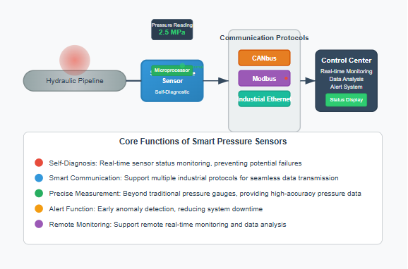
Modern hydraulic systems increasingly rely on pressure transducers integrated with smart sensor technology. These advanced versions of the traditional hydraulic pressure gauge can communicate via industrial protocols such as CANbus, Modbus, or Industrial Ethernet, enabling real-time monitoring and control from remote locations.
Smart pressure sensors incorporate microprocessors that can perform self-diagnostics, alerting operators to potential issues before they affect system performance. This predictive maintenance capability extends beyond simple pressure reading, as the hydraulic pressure gauge becomes an intelligent component capable of analyzing trends and patterns in system behavior.
Choosing the appropriate hydraulic pressure gauge requires careful consideration of multiple factors:
| Selection Criterion | Considerations |
|---|---|
| Pressure Range | The gauge must accommodate both normal operating pressures and potential shock pressures. A good rule of thumb is to select a hydraulic pressure gauge with a maximum reading of 1.5 to 2 times the normal system pressure. |
| Accuracy Requirements | Different applications demand varying levels of precision. Critical control applications may require a hydraulic pressure gauge with accuracy better than ±0.5%, while general monitoring applications might accept ±2% accuracy. |
| Environmental Conditions | Temperature extremes, vibration, and exposure to corrosive fluids all influence hydraulic pressure gauge selection. Liquid-filled gauges provide better vibration dampening, while stainless steel construction offers superior corrosion resistance. |
| Response Time | Dynamic applications requiring rapid pressure change detection need a hydraulic pressure gauge with fast response characteristics, typically achieved through electronic sensors rather than mechanical mechanisms. |
The performance and longevity of a hydraulic pressure gauge depend significantly on proper installation. Key considerations include:
Install the hydraulic pressure gauge away from sources of excessive vibration and heat. Avoid locations where hydraulic shock is likely to occur, such as immediately downstream of fast-acting valves.
Most mechanical gauges should be mounted vertically to ensure accurate readings. Digital hydraulic pressure gauge units typically offer more flexibility in mounting orientation.
Installing these devices between the system and the hydraulic pressure gauge helps protect against pressure spikes and pulsations, extending gauge life and improving reading stability.
Including an isolation valve allows the hydraulic pressure gauge to be removed for calibration or replacement without system shutdown.
Regular calibration ensures that a hydraulic pressure gauge maintains its specified accuracy throughout its service life. Calibration frequency depends on the criticality of the application, with safety-critical systems requiring more frequent verification.
The calibration process for a hydraulic pressure gauge typically involves:
When a hydraulic pressure gauge exhibits problems, systematic troubleshooting can identify the root cause:
Often caused by air in the system, mechanical vibration, or pressure pulsations. Installing a dampener or liquid-filled hydraulic pressure gauge can resolve these issues.
May indicate mechanical wear in analog gauges or electronic drift in digital units. Regular calibration of the hydraulic pressure gauge addresses this problem.
Can result from blocked impulse lines or excessive dampening. Cleaning impulse lines and adjusting dampener settings typically restore proper hydraulic pressure gauge response.
In mechanical gauges, this indicates overpressure damage. Selecting a hydraulic pressure gauge with appropriate pressure rating and installing overpressure protection prevents recurrence.
In industrial settings, the hydraulic pressure gauge plays a crucial role in ensuring consistent product quality and equipment reliability. Injection molding machines, for example, rely on precise pressure control monitored by multiple gauges throughout the hydraulic circuit.
Metal forming operations require specialized hydraulic pressure gauge designs capable of withstanding shock loads while maintaining accuracy.
Construction and agricultural equipment manufacturers integrate hydraulic pressure gauge systems into their designs for both operational monitoring and diagnostic purposes. Modern excavators may include dozens of pressure measurement points.
The harsh environment of mobile equipment demands robust hydraulic pressure gauge construction to withstand temperature extremes and vibration.
Aerospace applications represent some of the most demanding requirements for hydraulic pressure gauge performance. Aircraft hydraulic systems operate at pressures up to 5000 psi with strict accuracy requirements.
Military applications require hydraulic pressure gauge designs that can withstand shock, vibration, and electromagnetic interference in hostile environments.
Each application domain imposes unique requirements on hydraulic pressure gauge technology, from extreme temperature resistance in aerospace systems to rugged durability in construction equipment. The selection of appropriate pressure measurement devices must consider not only basic pressure range requirements but also environmental factors, response time needs, and integration capabilities with broader system monitoring infrastructure.
The evolution of the hydraulic pressure gauge continues with integration into IoT ecosystems. Connected pressure sensors enable cloud-based monitoring and analysis, providing unprecedented visibility into system performance across multiple locations. This connectivity transforms the humble hydraulic pressure gauge into a powerful diagnostic tool capable of predictive maintenance and optimization.
Advanced algorithms can now analyze patterns in hydraulic pressure gauge data to predict component failures before they occur. Machine learning models trained on historical pressure data can identify subtle anomalies that might escape human observation, enabling proactive maintenance strategies that minimize downtime and extend equipment life.
Micro-Electro-Mechanical Systems (MEMS) technology is revolutionizing hydraulic pressure gauge design, enabling smaller, more accurate, and less expensive sensors. These miniaturized devices can be integrated directly into hydraulic components, providing distributed pressure monitoring throughout the system.
The hydraulic pressure gauge remains an indispensable tool in modern hydraulic systems, evolving from simple mechanical devices to sophisticated digital instruments capable of comprehensive system monitoring and diagnostics. Understanding the complex pressure phenomena that occur in hydraulic systems, including hydraulic shock and cavitation, is essential for proper gauge selection and system design.