
The vane pump represents one of the most versatile and widely adopted hydraulic pump technologies in modern industrial applications. These sophisticated devices have revolutionized fluid power systems across various industries, from manufacturing to automotive applications. A vane pump operates on the principle of positive displacement, utilizing sliding vanes within a rotor to create chambers that expand and contract, thereby generating fluid flow. This fundamental design has evolved significantly since its inception, leading to numerous variations and improvements that address specific industrial requirements.
In hydraulic systems worldwide, the implementation of vane pump technology has become increasingly prevalent due to its unique combination of efficiency, reliability, and versatility. These pumps are characterized by their ability to deliver uniform flow output with minimal pulsation, low noise generation, and excellent volumetric efficiency under optimal conditions.
However, like any mechanical system, the vane pump also presents certain challenges, including relatively complex internal structures, specific oil cleanliness requirements, and sensitivity to contamination that must be carefully managed in practical applications.
The vane pump family can be broadly categorized into two primary classifications: single-acting (unbalanced) variable displacement pumps and double-acting (balanced) fixed displacement pumps. Each type offers distinct advantages and is suited to different operational requirements within hydraulic systems.
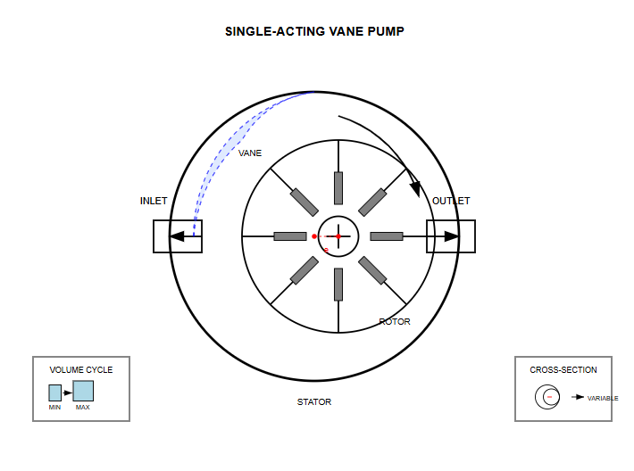
The single-acting vane pump, also known as an unbalanced or variable displacement pump, represents a fundamental design in hydraulic technology. This configuration features an eccentric relationship between the rotor and stator, which is crucial to its operation.
The eccentricity creates a crescent-shaped pumping chamber that varies in volume as the rotor turns, enabling the pump to perform one complete suction and discharge cycle per revolution.
The variable displacement capability of a single-acting vane pump makes it particularly valuable in applications requiring flow rate adjustment. By altering the eccentricity between the rotor and stator, operators can modify the pump's displacement, thereby controlling the output flow rate without changing the drive speed.
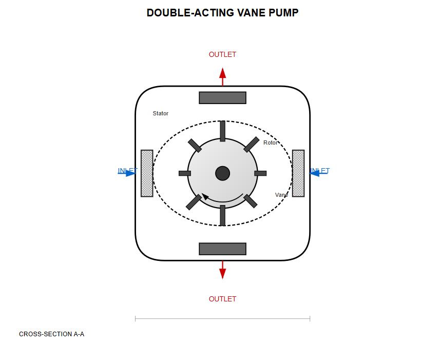
The double-acting vane pump, commonly referred to as a balanced or fixed displacement pump, employs a more sophisticated internal geometry. Unlike its single-acting counterpart, this design features a stator with an elliptical or cam-shaped internal surface.
The stator typically consists of two long-radius arcs, two short-radius arcs, and four transitional curves. The rotor and stator share the same center, eliminating the eccentricity found in single-acting designs.
This balanced configuration enables the vane pump to complete two suction and two discharge cycles per revolution, effectively doubling the pumping action. The symmetrical arrangement creates radially opposed hydraulic forces that cancel each other out, reducing bearing loads.
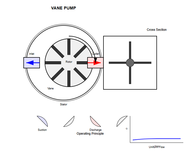
The operating principle of a vane pump centers on the creation and manipulation of sealed working chambers formed between adjacent vanes, the rotor, stator, and end plates. As the rotor spins, centrifugal force and hydraulic pressure combine to push the vanes radially outward, maintaining contact with the stator's inner surface.
This continuous contact ensures proper sealing between chambers, which is essential for efficient pump operation. In a typical vane pump cycle, the rotation causes chambers on one side to expand, creating a vacuum that draws fluid through the inlet port.
Simultaneously, chambers on the opposite side contract, forcing fluid out through the discharge port. The smooth, continuous nature of this process results in relatively uniform flow delivery with minimal pulsation compared to other positive displacement pump types.
Vane pump pressure cycle showing expansion and contraction phases
The reliable operation of any vane pump depends critically on maintaining proper vane-to-stator contact throughout the pumping cycle. Several mechanisms work in concert to achieve this essential requirement. Centrifugal force naturally pushes vanes outward as rotational speed increases, but this alone is insufficient, particularly during startup or low-speed operation.
To ensure consistent vane extension, most vane pump designs incorporate hydraulic pressure assist systems. These systems direct pressurized fluid to the base of the vane slots, creating an additional outward force that supplements centrifugal action. In single-acting pumps, the pressure distribution varies depending on the vane's position within the pump cycle. Vanes in the discharge zone experience balanced pressure on both surfaces, while those in the suction zone rely more heavily on centrifugal force and base pressure for proper extension.
The theoretical displacement of a single-acting vane pump can be calculated using geometric relationships between the pump's key dimensions. For a pump with Z vanes, stator inner diameter D, rotor diameter d, pump width b, vane thickness s, and eccentricity e, the displacement per revolution can be expressed through detailed mathematical analysis.
When vanes are radially oriented:
V = 2be(πD - Zs)
This fundamental equation reveals how each design parameter influences pump displacement. The eccentricity (e) and pump width (b) have direct linear relationships with displacement, while increasing the number of vanes (Z) slightly reduces displacement due to the volume occupied by the vanes themselves.
For vane pumps with angled vanes set at angle θ from the radial direction:
V = 2be(πD - Zs/cosθ)
The displacement calculation for a double-acting vane pump follows similar principles but accounts for the dual pumping action per revolution. With major radius R, minor radius r, rotor radius r₀, and other parameters as previously defined, the displacement becomes:
V = 2b[π(R² - r²) - (R - r)sZ/cosθ]
This equation demonstrates the increased displacement capability of double-acting designs. The actual flow rate, considering volumetric efficiency, is:
q = 2b[π(R² - r²) - (R - r)sZ/cosθ]nηᵥ
An important consideration in vane pump flow calculations is the influence of vane slot bottom volumes. In single-acting pumps where slot bottoms communicate with appropriate pressure zones, the volume changes in these spaces can compensate for displacement losses due to vane thickness.
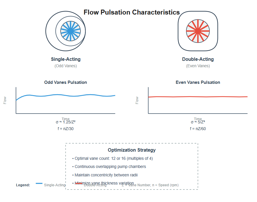
Flow pulsation represents a critical performance parameter in vane pump applications, particularly in precision hydraulic systems where smooth, consistent flow is essential. The pulsation characteristics differ significantly between single-acting and double-acting designs, with each presenting unique challenges and solutions.
Pulsation rate:
σ ≈ 1.25/Z²
Pulsation frequency:
f = nZ/30
Pulsation rate:
σ ≈ 5/Z³
Pulsation frequency:
f = nZ/60
Double-acting vane pump designs inherently produce more uniform flow output due to their continuous, overlapping pumping chambers. Theoretically, if vane thickness could be neglected and perfect concentricity maintained between major and minor radius arcs, the instantaneous flow would be completely uniform.
The optimal number of vanes for a double-acting vane pump is typically a multiple of four, with 12 or 16 vanes being most common. This configuration minimizes flow pulsation while maintaining practical manufacturing tolerances and mechanical strength.
The stator profile in a vane pump plays a crucial role in determining pump performance, efficiency, and longevity. In double-acting pumps, the transition curves connecting the major and minor radius arcs must be carefully designed to ensure smooth vane motion while maintaining proper sealing and minimizing wear.
Early vane pump designs often employed Archimedean spiral transition curves, which theoretically eliminated flow pulsation. However, these curves produced excessive radial accelerations at the connection points between curves and circular arcs, leading to impact loads, increased wear, and objectionable noise levels.
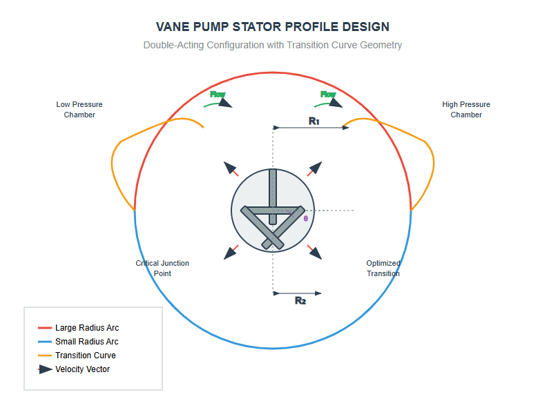
Contemporary vane pump designs frequently utilize "constant acceleration-constant deceleration" transition curves, which provide smoother vane motion and reduced impact loads. These curves can be expressed in polar coordinates as a function of angular position, with separate equations for the acceleration and deceleration phases of vane travel.
Smoother vane velocity changes
Reduced impact forces
Lower noise generation
Extended service life
To extend the pressure range of vane pump technology, manufacturers have developed several innovative design modifications. These advancements address the fundamental limitations of standard designs while maintaining the inherent advantages of vane pump technology.
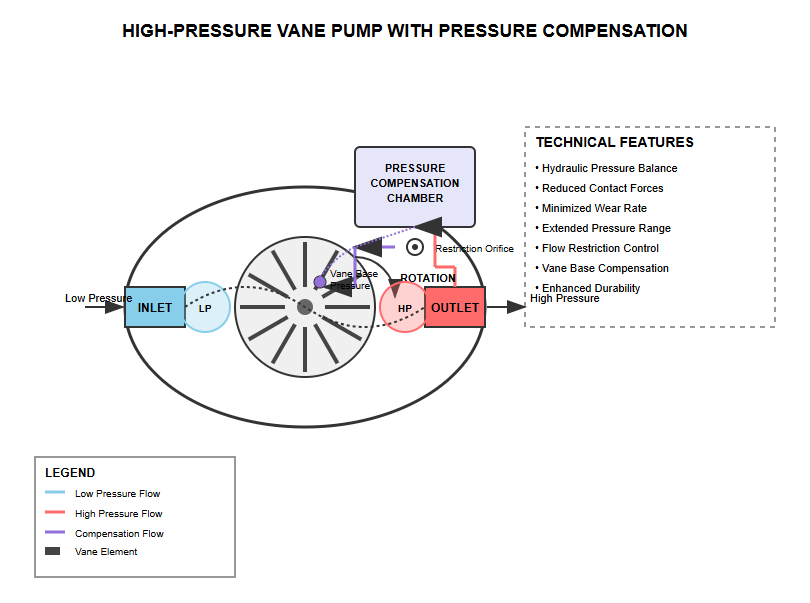
These systems modulate the hydraulic force acting on vane bases. By routing discharge pressure through restrictive passages to vane bases in suction zones, the differential pressure across vanes is reduced, minimizing contact forces and wear.
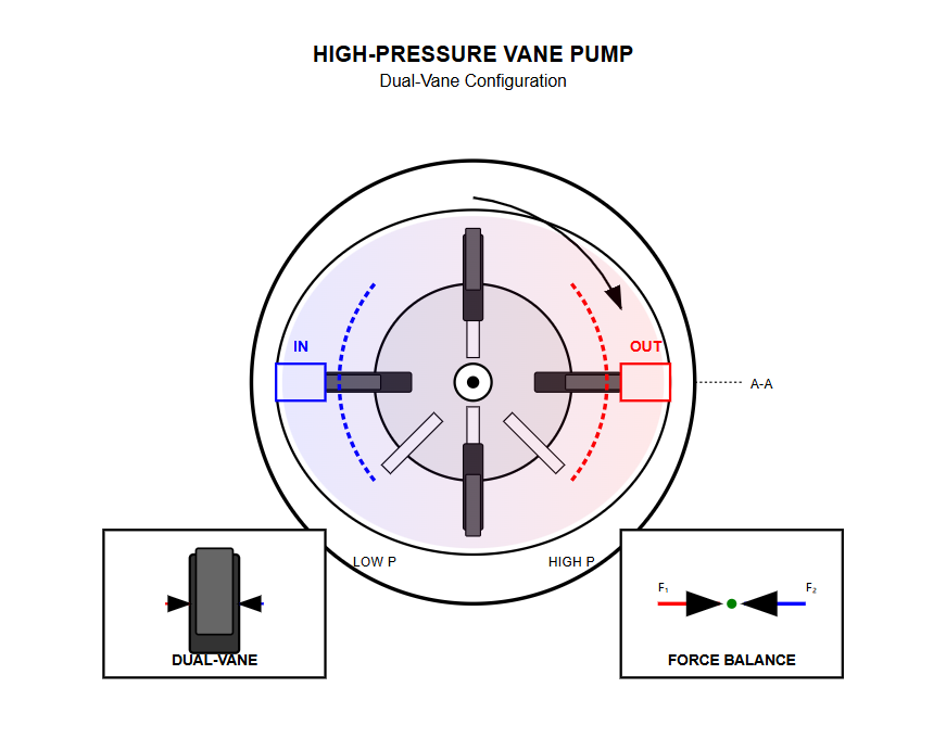
These designs effectively reduce the area subjected to differential pressure. Larger and smaller vanes work in tandem, with hydraulic pressure carefully controlled in the intermediate chamber to optimize force balance throughout the pumping cycle.
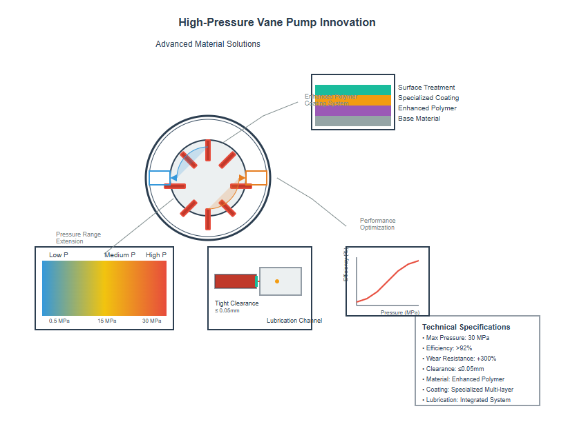
New material combinations including reinforced polymers and specialized coatings enhance wear resistance. These materials allow for tighter clearances and improved sealing at higher pressures while maintaining necessary lubrication properties.
The pressure-compensated variable vane pump represents a sophisticated evolution of basic variable displacement technology. These pumps automatically adjust their displacement in response to system pressure, providing excellent energy efficiency and system protection.
The control mechanism typically employs a feedback system that monitors discharge pressure and adjusts pump eccentricity accordingly. In external feedback designs, a separate control piston acts on the stator or swashplate assembly. System pressure acts on this piston against a spring force, creating a force balance that determines pump displacement.
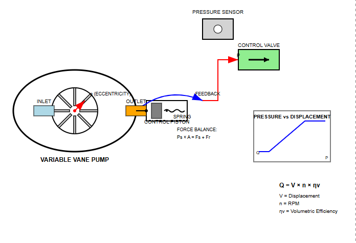
The performance curve of a pressure-compensated vane pump exhibits two distinct operating regions. In the first region, below the compensation pressure threshold, the pump operates at maximum displacement, behaving essentially as a fixed displacement pump.
Once system pressure exceeds the compensation threshold, the vane pump enters its variable displacement mode. In this region, pump displacement decreases rapidly with increasing pressure, maintaining a relatively constant power consumption. The maximum pressure capability occurs when displacement reduces to the point where all theoretical flow is consumed by internal leakage, at which point net output flow becomes zero.
The vane pump finds extensive application across diverse industrial sectors due to its favorable combination of performance characteristics. In machine tool applications, these pumps excel at providing the variable flow rates required for rapid traverse and controlled feed movements.
Material handling equipment frequently employs vane pump technology for hydraulic power generation. The moderate pressure capabilities and excellent efficiency at partial loads make these pumps well-suited for applications such as lift trucks and conveyor systems.
The relatively quiet operation of vane pumps is particularly valued in indoor industrial environments where noise reduction is important.
In mobile hydraulic applications, the vane pump serves various functions from primary power generation to auxiliary system support. Agricultural equipment utilizes these pumps for implement control and power steering systems.
The ability of pressure-compensated vane pumps to automatically adjust flow based on demand provides significant fuel savings in mobile applications. Construction equipment manufacturers often specify vane pump systems for auxiliary functions.
The compact design and favorable power-to-weight ratio of modern vane pumps make them attractive for space-constrained mobile installations.
The automotive industry has long recognized the benefits of vane pump technology, particularly in power steering and automatic transmission applications. The smooth, quiet operation contributes to vehicle refinement.
In automatic transmissions, the vane pump provides the hydraulic pressure necessary for clutch actuation and lubrication. The consistent pressure delivery contributes to smooth shift quality and transmission durability.
Advanced designs incorporate variable displacement features that reduce parasitic losses during cruise conditions, further improving vehicle efficiency.
Successful long-term operation of any vane pump system depends on implementing comprehensive preventive maintenance programs. Regular monitoring of key performance indicators can identify developing issues before they result in catastrophic failure.
Fluid condition monitoring represents perhaps the most critical aspect of vane pump maintenance. These pumps exhibit higher sensitivity to contamination than gear pumps, making regular oil analysis essential. Implementing appropriate filtration systems and maintaining them properly significantly extends pump life.
Understanding common failure modes enables more effective troubleshooting when vane pump problems arise. Early detection of issues can prevent secondary damage to other system components and minimize downtime.
Typically results from contamination, inadequate lubrication, or operation beyond design parameters.
Symptoms: Reduced volumetric efficiency, increased noise, elevated operating temperatures.
Often caused by varnish formation or particle contamination restricting vane movement.
Symptoms: Erratic flow delivery, increased flow pulsation, unusual noise patterns.
Can occur due to chemical incompatibility, excessive temperatures, or pressure spikes.
Symptoms: External leaks, reduced system pressure, fluid contamination.
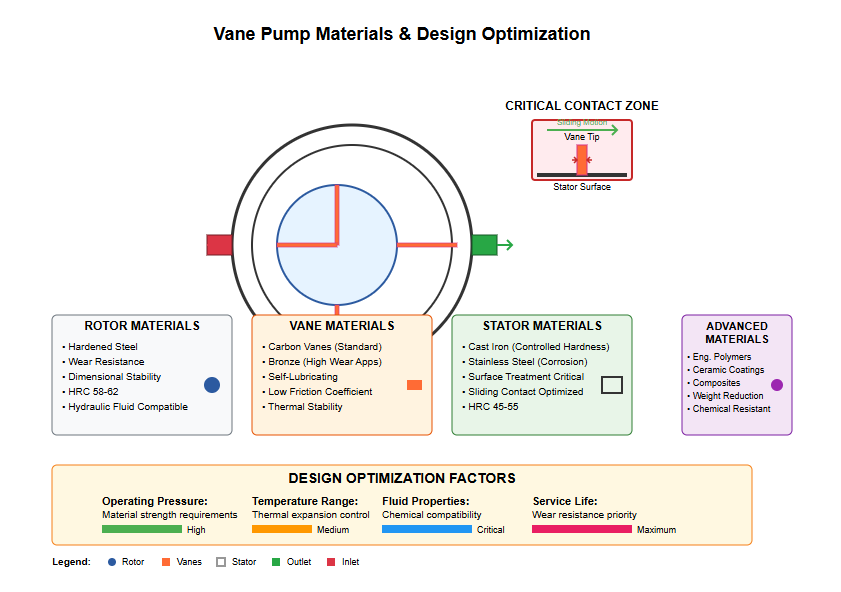
The selection of appropriate materials for vane pump components significantly impacts performance, durability, and chemical compatibility. Rotor and vane materials must exhibit excellent wear resistance, dimensional stability, and compatibility with hydraulic fluids.
Stator materials and surface treatments deserve particular attention in vane pump design due to the continuous sliding contact with vane tips. The selection of appropriate material combinations considers factors including operating pressure, temperature range, fluid properties, and expected service life.
Precise control of internal clearances critically affects vane pump performance and efficiency. Excessive clearances increase internal leakage, reducing volumetric efficiency and limiting pressure capability. Conversely, insufficient clearances can cause mechanical interference, resulting in increased wear, heat generation, and potential seizure.
| Clearance Type | Typical Range | Performance Impact |
|---|---|---|
| Vane tip to stator | 0.01-0.05 mm | Primary seal for pressure chambers |
| Vane side to rotor slot | 0.02-0.08 mm | Controls lateral leakage, allows vane movement |
| Rotor to end plate | 0.03-0.10 mm | Significant impact on volumetric efficiency |
| Shaft to bearing | 0.01-0.03 mm | Affects alignment and radial load capacity |
Contemporary vane pump development increasingly focuses on hybrid systems that combine the advantages of different pump technologies. Integration of vane pump elements with gear or piston pump stages creates multi-stage systems capable of delivering high pressure at improved efficiency.
These hybrid configurations leverage the smooth flow characteristics of vane pumps for low-pressure stages while utilizing the high-pressure capability of piston pumps for final pressure generation.
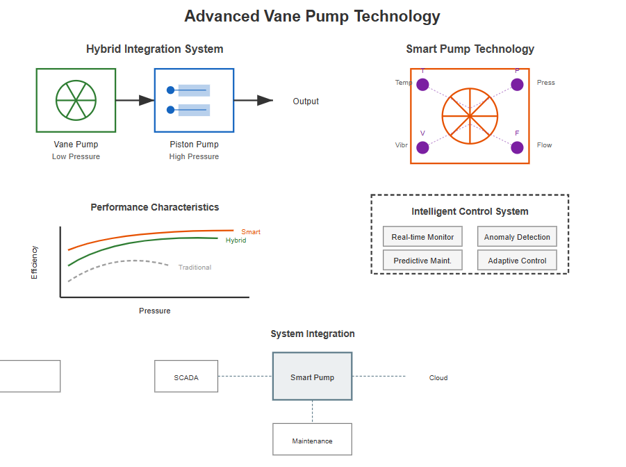
The integration of sensors and intelligence into vane pump systems enables predictive maintenance and performance optimization capabilities. Embedded sensors monitor parameters such as temperature, pressure, vibration, and flow in real-time, providing continuous insight into pump condition.
Smart vane pump systems can communicate with supervisory control systems, enabling enterprise-level optimization of hydraulic power generation and distribution. These pumps can automatically adjust their operating characteristics based on system-wide efficiency objectives, load sharing requirements, or energy cost considerations.
Real-time performance monitoring
Anomaly detection
Predictive maintenance
Adaptive control
The growing emphasis on energy conservation has driven significant improvements in vane pump efficiency. Modern designs incorporate features such as optimized porting geometry, reduced internal leakage paths, and low-friction surface treatments to maximize overall efficiency.
System-level efficiency optimization considers the entire hydraulic circuit, not just the vane pump in isolation. Proper sizing ensures pumps operate near their peak efficiency points for typical duty cycles. Integration of accumulator systems with vane pumps can reduce peak power requirements.
Environmental regulations increasingly influence vane pump design and application decisions. The transition to environmentally friendly hydraulic fluids requires careful consideration of material compatibility and lubrication requirements.
Noise reduction represents another important environmental consideration for vane pump applications. Advanced design techniques including optimized porting geometry, reduced cavitation through improved inlet design, and isolation mounting systems contribute to quieter pump operation.
The future of vane pump technology promises continued evolution driven by advances in materials science, manufacturing processes, and control systems. Additive manufacturing techniques enable creation of complex internal geometries previously impossible with conventional machining.
Advanced materials including ceramics, composites, and nanostructured coatings offer potential for significant improvements in vane pump performance and durability. These materials could enable operation at higher pressures and temperatures.
The vane pump market continues to evolve in response to changing industrial requirements and technological capabilities. Increasing automation and the growth of Industry 4.0 concepts drive demand for intelligent, connected pumps.
Electrification trends in mobile equipment create new opportunities and challenges. Electric-driven hydraulic systems require pumps optimized for variable-speed operation, potentially eliminating the need for variable displacement mechanisms in some applications.
The vane pump continues to represent a vital technology in fluid power systems across numerous industries and applications. Its unique combination of smooth flow delivery, moderate pressure capability, and design flexibility ensures ongoing relevance.
As hydraulic systems become increasingly sophisticated, vane pump technology must evolve to meet these challenges. Through continued innovation, modern vane pumps deliver performance levels that would have seemed impossible just decades ago.