
A cornerstone technology in modern hydraulic machinery and industrial applications
The plunger pump represents one of the most significant developments in hydraulic machinery, serving as a cornerstone technology in modern industrial applications. These sophisticated mechanical devices have evolved from simple reciprocating mechanisms to highly efficient, variable displacement systems capable of delivering precise fluid flow under extreme pressures. Understanding the fundamental principles and operational characteristics of plunger pump systems is essential for engineers and technicians working in hydraulic power transmission, industrial automation, and fluid control systems.
Engineered for high-pressure applications with tight tolerances and specialized sealing arrangements.
Designed to minimize internal leakage while maintaining high volumetric efficiency across operating ranges.
Available in various configurations to suit diverse industrial applications and operational requirements.
A plunger pump operates on the principle of positive displacement, where fluid is mechanically trapped and then forced through the discharge port. The core mechanism involves plungers that reciprocate within precisely machined cylinders, creating alternating suction and discharge cycles. During the suction stroke, the plunger retracts, creating a partial vacuum that draws fluid into the cylinder chamber. Subsequently, during the discharge stroke, the plunger advances, compressing the fluid and forcing it through the outlet port at high pressure.
The efficiency of a plunger pump depends significantly on the sealing between the plunger and cylinder bore. Unlike piston pumps that rely on rings for sealing, plunger pump designs typically feature close-tolerance fits and specialized sealing arrangements that minimize internal leakage while maintaining high volumetric efficiency. This characteristic makes the plunger pump particularly suitable for high-pressure applications where conventional pumping solutions might fail.
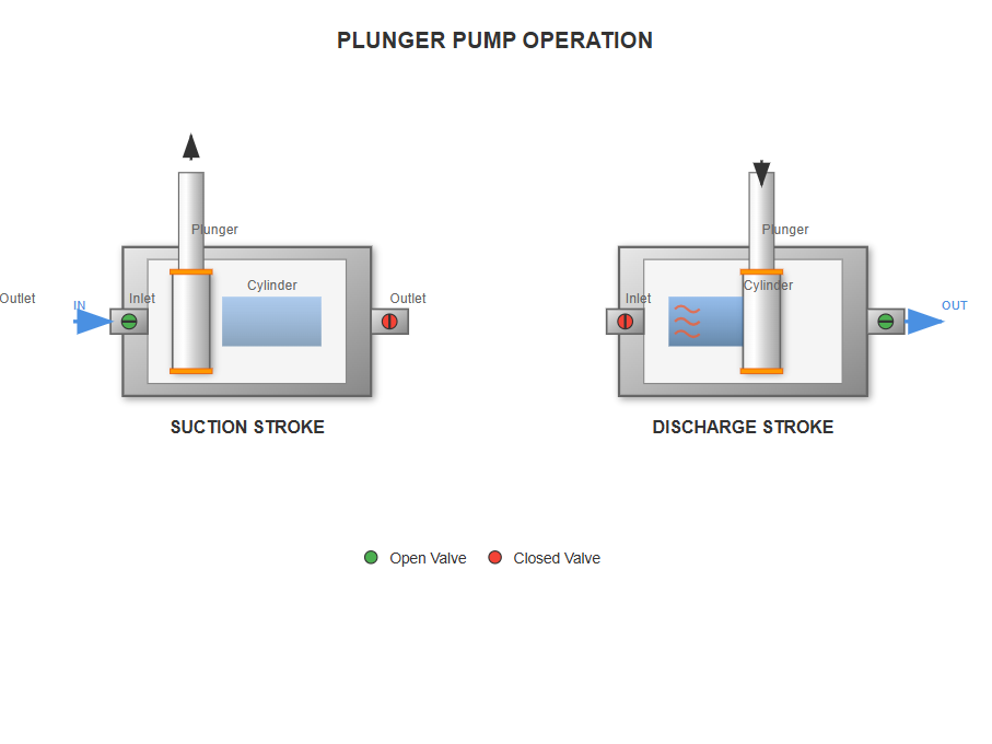
Plunger pump operation showing suction and discharge cycles
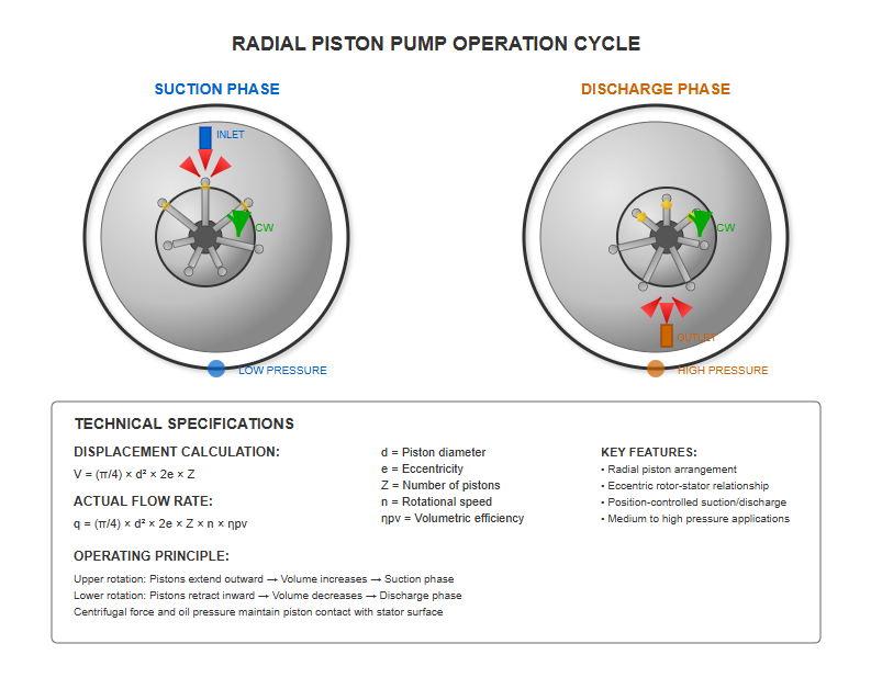
The radial plunger pump represents a unique configuration where plungers are arranged radially around a central rotor or cylinder block. In this design, the rotor contains multiple radially positioned plunger bores, each housing a plunger that can slide freely within its bore. The operational principle involves an eccentric relationship between the rotor center and the stator center, characterized by an eccentricity distance 'e'.
When the rotor rotates clockwise, centrifugal force or low-pressure oil pushes the plungers outward against the inner wall of the stator. During the upper half of rotation, plungers extend outward, increasing the sealed working volume and creating a partial vacuum that draws oil from the reservoir through the distribution shaft's inlet ports. Conversely, during the lower half of rotation, the stator surface pushes the plungers inward, decreasing the sealed volume and forcing oil out through the discharge ports.
V = (π/4) × d² × 2e × Z
q = (π/4) × d² × 2e × Z × n × ηpv
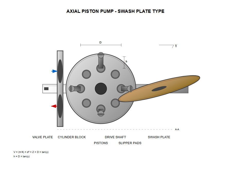
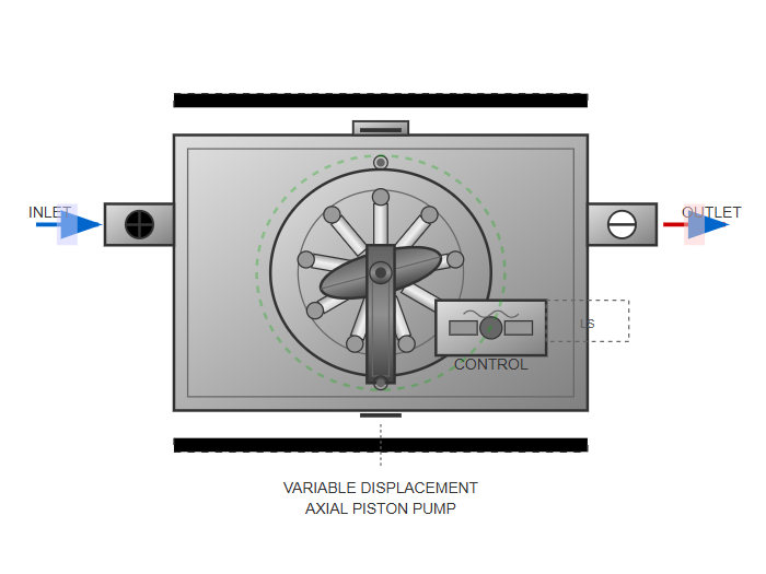
Axial plunger pump designs feature plungers arranged parallel to the drive shaft axis, offering superior compactness and power density compared to radial configurations. These pumps are further categorized into two main types: swash plate and bent axis designs.
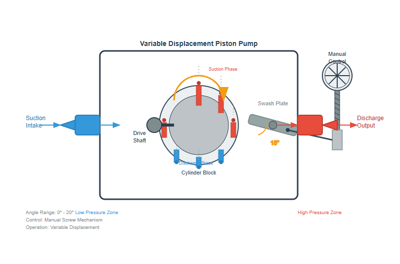
In a swash plate plunger pump, the cylinder block rotates with the drive shaft while the swash plate remains stationary at an angle γ to the shaft axis. The plungers, uniformly distributed within the cylinder block, maintain contact with the swash plate through slipper pads or mechanical linkages. As the cylinder block rotates, plungers undergo reciprocating motion determined by the swash plate angle.
h = D × tan(γ)
Where D represents the plunger pitch circle diameter
V = (π/4) × d² × Z × D × tan(γ)
This design allows for variable displacement by adjusting the swash plate angle, making the plunger pump highly versatile for applications requiring flow control.
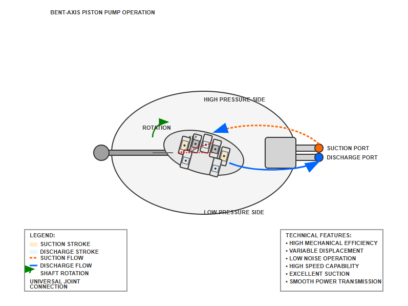
The bent axis plunger pump features a cylinder block tilted at an angle relative to the drive shaft. Connected through universal joints or similar mechanisms, this configuration provides smooth power transmission while allowing plunger reciprocation. The displacement characteristics are similar to swash plate designs but offer different mechanical advantages in certain applications.
Modern plunger pump designs incorporate sophisticated slipper pad mechanisms to improve efficiency and durability. These components serve as the interface between plungers and the swash plate, converting rotational motion to linear reciprocation. The slipper design employs hydrostatic bearing principles, where a thin film of pressurized fluid separates the sliding surfaces.
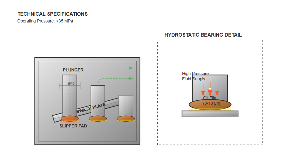
A central orifice in the plunger channels high-pressure fluid to the slipper face, creating a hydrostatic force that counterbalances the mechanical loading. The pressure balance coefficient Mq, typically maintained between 1.05 and 1.10, ensures optimal film thickness while preventing metal-to-metal contact. This technology enables the plunger pump to operate at pressures exceeding 35 MPa with minimal wear.
The instantaneous flow rate of an individual plunger follows a sinusoidal pattern:
q' = (π × d²/4) × (D/2) × ω × tan(γ) × sin(ωt)
The overall pump flow results from superimposing individual plunger flows, creating inherent pulsations. The pulsation coefficient σ depends on the number of plungers:
σ = (π/2Z) × tan(π/4Z)
σ = (π/Z) × tan(π/2Z)
Analysis shows that using an odd number of plungers, typically 7 or 9, minimizes flow pulsation while maintaining practical design constraints.
Manual variable displacement systems in a plunger pump employ mechanical linkages to adjust swash plate angle. The operator rotates a handwheel connected to a lead screw mechanism, which translates rotational motion into linear displacement of the control piston. This piston, through pivot pins and linkages, adjusts the swash plate angle between 0° and typically 20°.
The manual system offers simplicity and reliability but requires significant operating force, particularly under high-pressure conditions. Therefore, manual adjustment is typically performed during shutdown or low-pressure operation.
Advanced plunger pump designs incorporate automatic pressure compensation mechanisms that adjust displacement based on system pressure. These systems maintain nearly constant power output by reducing flow as pressure increases, following an approximate hyperbolic relationship.
The control system consists of a servo valve responding to outlet pressure, which modulates the position of the displacement control piston. At pressures below the compensation threshold (typically 3-7 MPa), the pump operates at maximum displacement. As pressure increases, the servo valve redirects flow to adjust the swash plate angle, reducing displacement proportionally.
The volumetric efficiency of a plunger pump depends on several factors including internal clearances, fluid viscosity, operating pressure, and temperature. Typical volumetric efficiencies range from 92% to 98% for well-designed units. Minimizing internal leakage paths through precision manufacturing and appropriate material selection is crucial for maintaining high efficiency.
The clearance between plunger and bore must balance conflicting requirements: tight clearances reduce leakage but increase friction and heat generation. Modern plunger pump designs employ advanced surface treatments and materials to optimize this balance, achieving exceptional performance across wide operating ranges.
Mechanical losses in a plunger pump arise from friction between moving components, particularly at the plunger-bore interface, slipper-swash plate contact, and bearing surfaces. Proper lubrication, surface finish quality, and material compatibility significantly influence mechanical efficiency, typically ranging from 88% to 95%.
The overall efficiency of a plunger pump, combining volumetric and mechanical efficiencies, can exceed 85% under optimal conditions. This high efficiency, coupled with the ability to generate extremely high pressures, makes these pumps invaluable in industrial hydraulic systems.
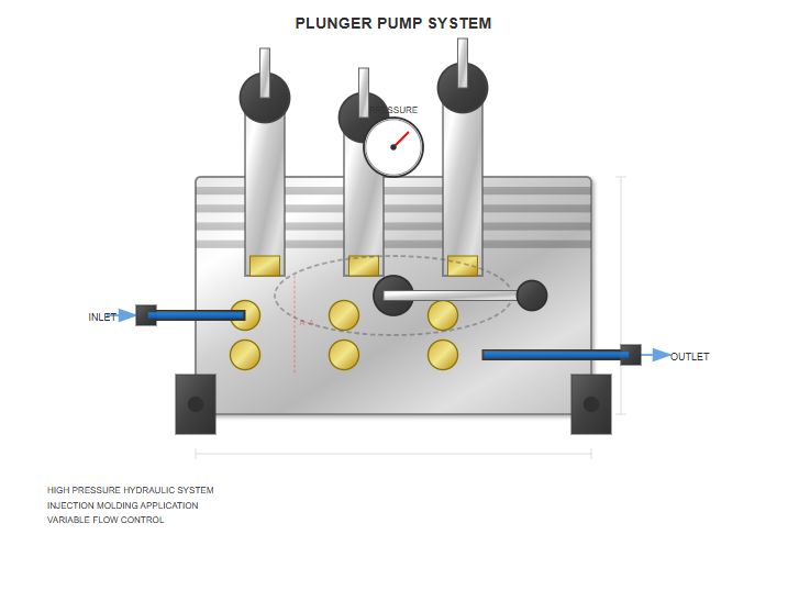
Provide high pressure for plastic injection while offering variable flow for different cycle phases.
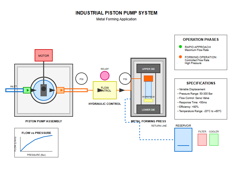
Deliver maximum flow during rapid approach and controlled flow during forming operations.
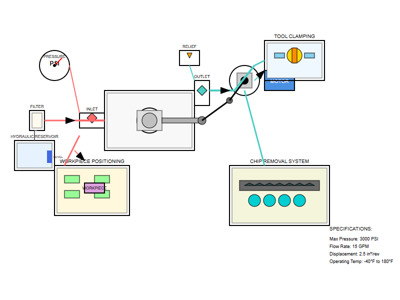
Used for tool clamping, workpiece positioning, and chip removal systems with precise control.
The plunger pump serves as the primary power source in numerous industrial hydraulic applications. Manufacturing automation increasingly relies on plunger pump technology for precise motion control. The consistent pressure delivery and flow control capabilities enable accurate, repeatable operations essential for modern manufacturing.
Construction and agricultural machinery extensively utilize plunger pump systems for their power density and efficiency advantages. Excavators employ variable displacement pumps to optimize power distribution between multiple hydraulic functions. The load-sensing capabilities of modern plunger pump designs enable fuel-efficient operation by matching pump output to actual demand.
In mobile applications, the compact design of axial plunger pump configurations proves particularly advantageous. The high power-to-weight ratio allows equipment designers to maximize payload capacity while maintaining superior hydraulic performance. Advanced electronic controls further enhance efficiency by coordinating pump displacement with engine speed and load conditions.
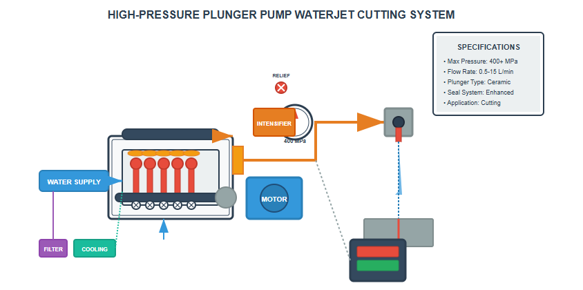
High-pressure water jet cutting systems rely on specialized plunger pump designs capable of generating pressures exceeding 400 MPa. These ultra-high-pressure pumps feature reinforced components and specialized sealing systems to withstand extreme operating conditions. The consistent pressure delivery ensures uniform cutting quality across various materials.
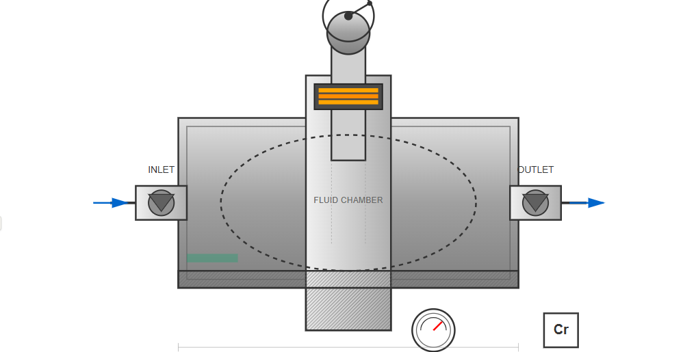
Chemical processing industries utilize plunger pump technology for precise metering and injection applications. The positive displacement characteristic ensures accurate flow delivery independent of system pressure variations. Specialized materials and sealing systems enable compatibility with corrosive fluids while maintaining reliability.
Effective maintenance of plunger pump systems requires systematic monitoring of key performance indicators. Regular oil analysis reveals contamination levels and component wear patterns before catastrophic failure occurs. Vibration monitoring detects bearing degradation and mechanical imbalances that could compromise pump performance.
Monitor contamination levels, wear particles, and fluid condition to predict maintenance needs.
Detect abnormal patterns indicating bearing wear, misalignment, or cavitation issues.
Monitor operating temperatures to identify increased friction or inadequate cooling.
Temperature monitoring provides insights into pump efficiency and potential problems. Excessive heat generation indicates increased internal friction, possibly due to wear or inadequate lubrication. Establishing baseline temperature profiles enables early detection of developing issues.
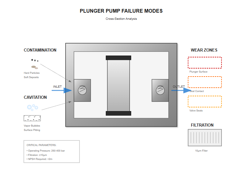
Understanding typical failure mechanisms helps optimize plunger pump reliability. Contamination-induced wear represents the most common failure mode, emphasizing the importance of proper filtration. Particles harder than component materials cause accelerated wear, while soft contaminants can create deposits affecting valve operation.
Cavitation damage occurs when local pressure drops below fluid vapor pressure, creating vapor bubbles that violently collapse. This phenomenon erodes surfaces and generates noise and vibration. Proper system design, including adequate inlet conditions and appropriate pump sizing, prevents cavitation-related failures.
Systematic troubleshooting of plunger pump problems requires understanding the relationship between symptoms and root causes. Reduced flow output might indicate worn components, incorrect displacement setting, or excessive internal leakage. Pressure fluctuations suggest valve problems, air entrainment, or control system malfunctions.
| Symptom | Possible Causes | Recommended Actions |
|---|---|---|
| Reduced flow output |
|
|
| Pressure fluctuations |
|
|
| Excessive noise |
|
|
Excessive noise generation typically stems from cavitation, aeration, or mechanical wear. Identifying the noise characteristics—frequency, intensity, and variation with operating conditions—helps pinpoint the source. High-frequency noise often indicates cavitation, while low-frequency rumbling suggests bearing problems.
Research into advanced materials promises improved plunger pump performance and longevity. Ceramic and cermet components offer exceptional wear resistance and chemical compatibility.
Nano-structured surface treatments show promise for reducing friction and wear in plunger pump applications. Self-lubricating materials eliminate the need for external lubrication in certain applications.
Industry 4.0 concepts are transforming plunger pump technology through digital integration. Embedded sensors monitor operating parameters in real-time, enabling predictive maintenance and performance optimization.
Digital twin technology creates virtual models of plunger pump systems, enabling simulation-based optimization and troubleshooting with real-time operational data.
Increasing focus on energy efficiency drives innovation in plunger pump design. Variable speed drives optimize pump speed based on flow requirements, reducing energy consumption during partial load operation.
Recovery of hydraulic energy through regenerative circuits improves overall system efficiency. During deceleration, the plunger pump can function as a motor, converting energy back to mechanical or electrical.
The plunger pump remains an essential component in modern hydraulic systems, combining high efficiency with exceptional pressure capabilities. Understanding the fundamental principles, design variations, and application requirements enables optimal selection and implementation. Continued technological advancement ensures that plunger pump systems will remain vital for industrial automation, mobile machinery, and specialized processes.
The evolution from simple reciprocating mechanisms to sophisticated variable displacement systems demonstrates the ongoing importance of plunger pump technology. As industries demand higher performance, improved efficiency, and enhanced reliability, pump manufacturers continue innovating to meet these challenges. The integration of digital technologies, advanced materials, and intelligent controls positions the plunger pump at the forefront of hydraulic power transmission technology.
Through proper selection, installation, and maintenance, plunger pump systems deliver reliable, efficient operation across diverse applications. The fundamental advantages of positive displacement, high pressure capability, and precise flow control ensure their continued relevance in advancing industrial technology. As manufacturing processes become increasingly sophisticated and environmental regulations more stringent, the role of efficient hydraulic power transmission becomes ever more critical, cementing the position of the plunger pump as an indispensable industrial technology.