
The cylinder hydraulic system represents one of the most fundamental and versatile components in modern fluid power technology. As an essential actuator in hydraulic systems, these devices serve the critical function of converting hydraulic energy into mechanical energy.
In industrial applications ranging from construction machinery to manufacturing equipment, the cylinder hydraulic mechanism provides reliable linear motion and force generation.
The cylinder hydraulic operates on the fundamental principle of Pascal's law, which states that pressure applied to a confined fluid is transmitted equally in all directions. In practical terms, this means that when pressurized hydraulic fluid enters the cylinder chamber, it exerts force on the piston surface, creating linear motion.
The input parameters for any cylinder hydraulic system include fluid flow rate and pressure, while the output parameters consist of linear velocity and force.
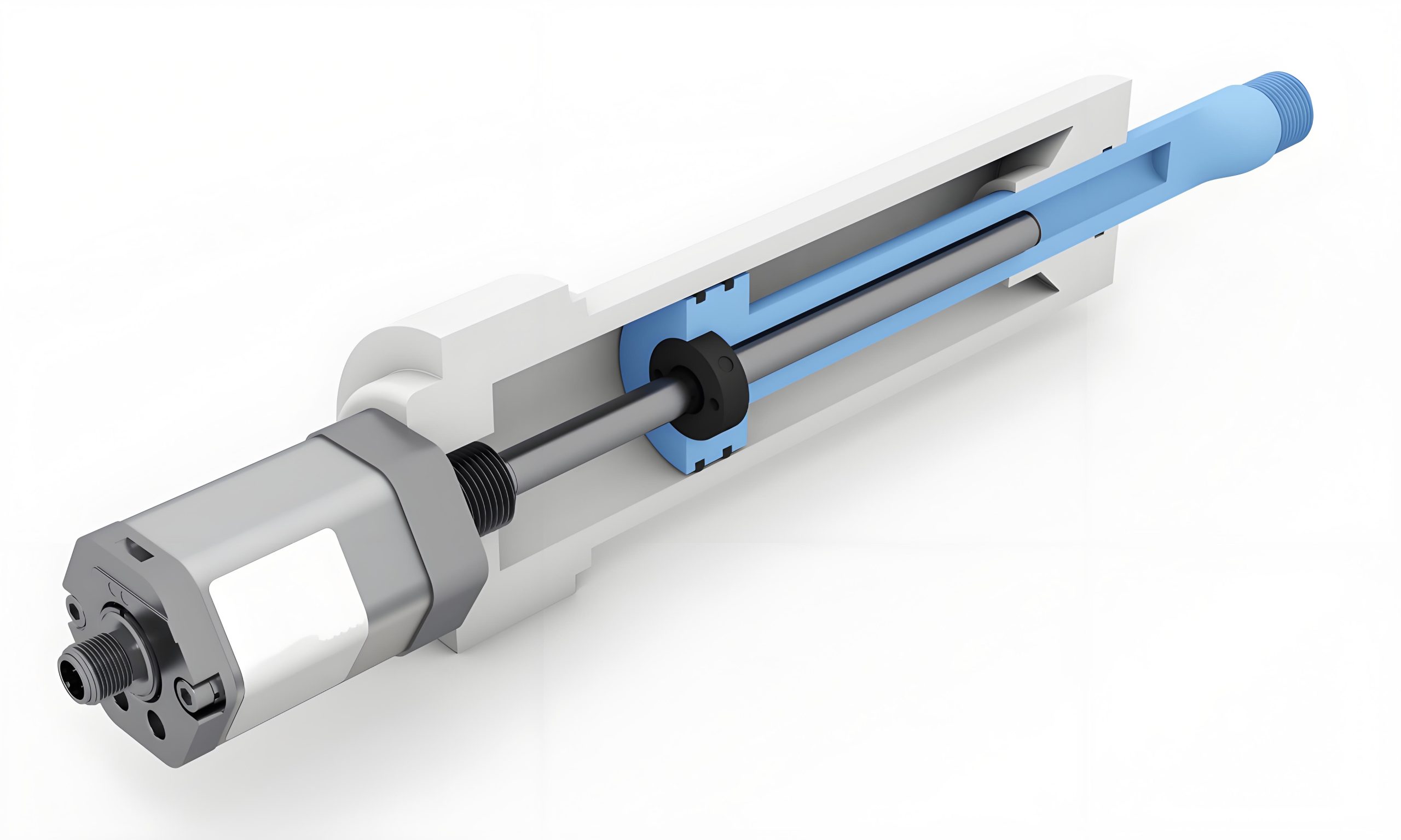
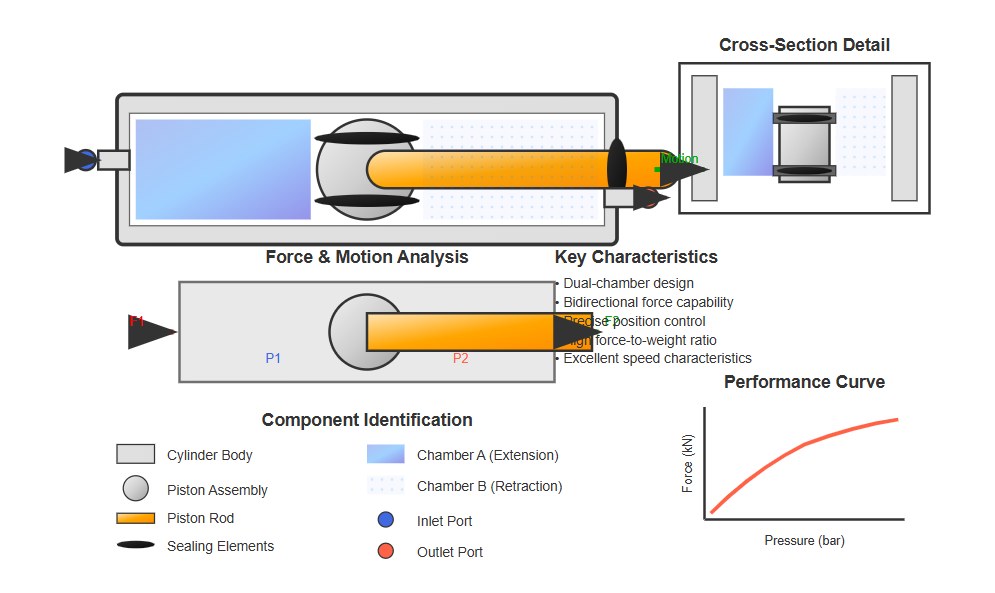
The basic construction of a hydraulic cylinder comprises several essential components: the cylinder barrel (or tube), piston, piston rod, end caps, and sealing elements. These components work in harmony to ensure efficient energy conversion and reliable operation.
The cross-section reveals the key components working together to convert hydraulic energy into mechanical motion.
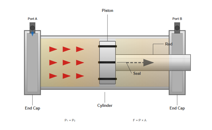
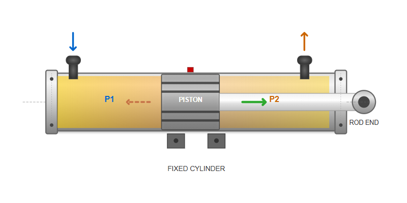
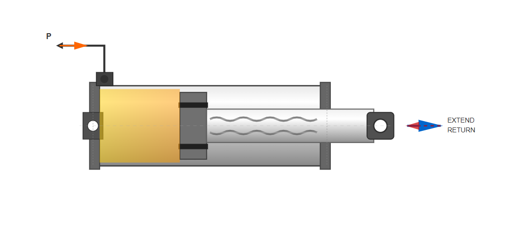
In a fixed cylinder hydraulic arrangement, the cylinder barrel remains stationary while the piston and rod assembly moves. When hydraulic fluid continuously enters the left chamber at sufficient pressure to overcome all external loads on the piston rod, the piston moves toward the right.
Conversely, introducing pressurized fluid into the right chamber causes the piston to move leftward, again performing work on the external load. This reciprocating motion constitutes the fundamental operating cycle.
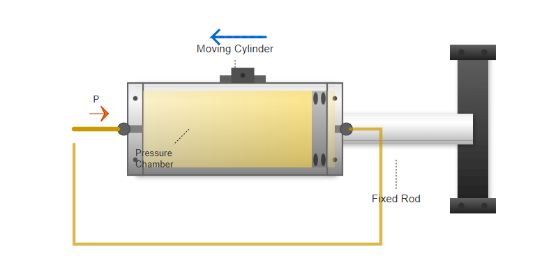
An alternative configuration involves fixing the piston rod while allowing the cylinder barrel to move. In this cylinder hydraulic arrangement, introducing pressurized fluid into the left chamber causes the cylinder barrel to move leftward.
This configuration, though less common than the fixed cylinder type, finds application in specific industrial scenarios where moving the cylinder barrel offers advantages in terms of space constraints or mechanical design.
"The efficiency of cylinder hydraulic systems has improved significantly with advances in seal technology and precision manufacturing, achieving volumetric efficiencies exceeding 95% in modern designs while reducing internal leakage to negligible levels through improved surface finishing and advanced seal materials"
— Johnson et al., 2024
International Journal of Fluid Power, Volume 25, Issue 2, 2024
The energy conversion process in a cylinder hydraulic system involves transforming hydraulic energy (pressure and flow) into mechanical energy (force and velocity). This conversion occurs with high efficiency when proper design principles are followed.
The hydraulic fluid must possess adequate pressure (p) to overcome the load resistance and sufficient flow rate (q) to achieve the desired movement speed. These input parameters directly determine the cylinder's output force (F) and velocity (v), establishing the four primary performance parameters.
Single-acting cylinders receive high-pressure hydraulic fluid on only one side of the piston, relying on external forces such as gravity, springs, or mechanical loads for the return stroke. This design simplicity makes single-acting cylinders cost-effective for applications where return force is readily available.
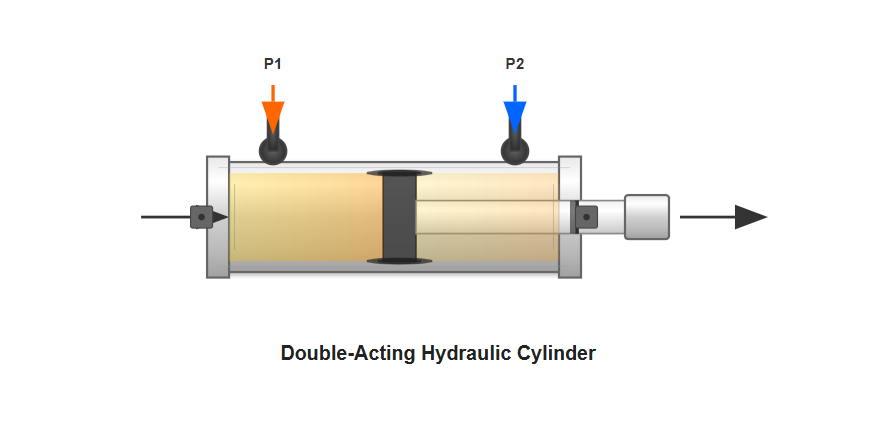
Double-acting cylinders, representing the majority of cylinder hydraulic applications, utilize hydraulic pressure for both extension and retraction movements. By supplying pressurized fluid alternately to either side of the piston, these cylinders provide positive control over both stroke directions.
The most common type, featuring a piston with seals that separate the cylinder into two distinct chambers. These versatile units provide excellent force and speed characteristics.
Also known as ram cylinders, utilize a single rod that acts as both piston and output member, offering simplicity and robustness for high-force applications.
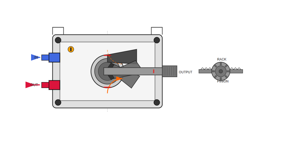
Sometimes called rotary actuators, convert hydraulic pressure into rotational motion through mechanisms such as rack-and-pinion or vane designs.
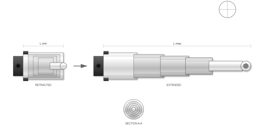
Feature multiple nested stages that extend sequentially to achieve long strokes from compact retracted lengths, ideal for space-constrained applications.
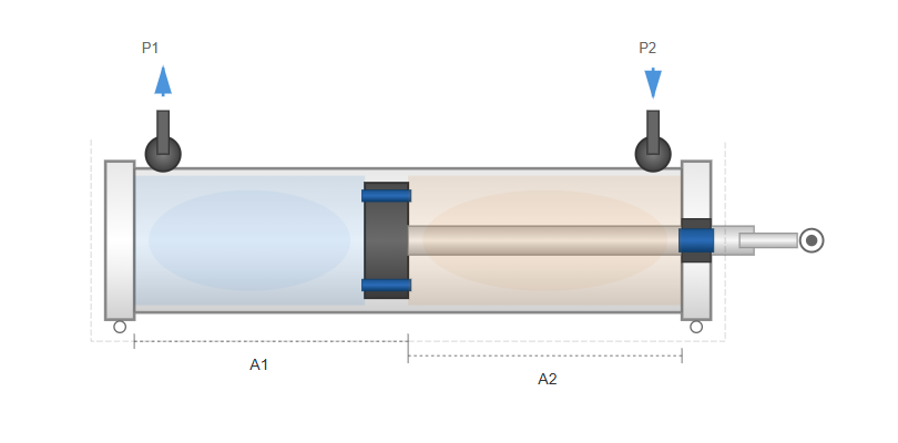
Featuring a piston rod extending from only one end, these represent the most common configuration. These cylinders exhibit different force and speed characteristics for extension and retraction due to the differential areas on either side of the piston.
Key Characteristic:
Different force capabilities in extension vs. retraction due to rod area reducing effective piston area on one side.
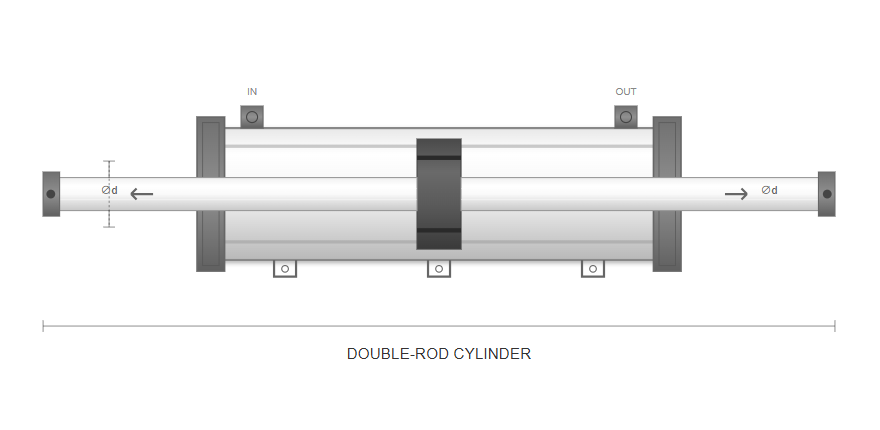
Incorporate piston rods extending from both ends of the cylinder. When both rods have equal diameters, the cylinder hydraulic provides identical force and speed characteristics in both directions.
Key Characteristic:
Symmetrical design suits applications requiring uniform performance regardless of stroke direction.
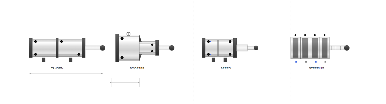
| Cylinder Type | Design Feature | Primary Application |
|---|---|---|
| Tandem Cylinders | Connect two or more cylinders in series to generate high forces when diameter constraints exist. | High-pressure applications with space limitations |
| Intensifier Cylinders | Utilize pressure intensification principle with two different piston areas to generate extremely high pressures. | Hydraulic presses and clamping systems |
| Speed Multiplication Cylinders | Employ differential area ratios to achieve rapid extension speeds exceeding normal pump capabilities. | Applications requiring quick positioning movements |
| Step Cylinders | Provide discrete positioning through multiple pistons with binary-scaled strokes for predetermined positions. | Positioning systems without sophisticated controls |
The performance of any cylinder hydraulic system depends fundamentally on the relationships between pressure, flow, force, and velocity. The force generated by a hydraulic cylinder equals the product of effective piston area and applied pressure, minus losses due to friction and back pressure.
For single-rod cylinders, the extension force exceeds the retraction force due to the rod area reducing the effective piston area on the rod side.
Speed characteristics follow similar principles, with cylinder velocity determined by flow rate divided by effective piston area. The cylinder hydraulic must be properly sized to ensure adequate force generation while maintaining acceptable velocities for the application.
Force Calculation:
F = P × A
Where F = Force, P = Pressure, A = Effective Area
Velocity Calculation:
V = Q ÷ A
Where V = Velocity, Q = Flow Rate, A = Effective Area
Oversizing leads to sluggish operation and increased system costs, while undersizing results in insufficient force or excessive operating pressures.
Relationship between cylinder size, operating pressure, and resulting force and velocity
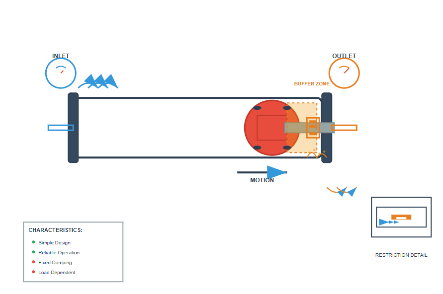
Many cylinder hydraulic applications require deceleration at stroke ends to prevent damaging impacts. Various cushioning mechanisms address this need with different approaches to controlled deceleration.
Fixed cushioning designs incorporate restrictive passages that throttle exhaust flow as the piston approaches the stroke end, creating a cushioning effect.
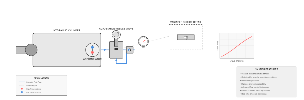
Adjustable cushioning systems provide variable deceleration rates through adjustable needle valves or similar flow control devices, optimizing for specific conditions.
Differential cylinders represent a special category of cylinder hydraulic designs where the area ratio between the piston and annulus sides creates distinctive operating characteristics. When the rod diameter approaches the piston diameter, small annulus areas result in high retraction speeds with reduced force capability.
This configuration suits applications requiring rapid return strokes where minimal force suffices.
The differential cylinder hydraulic can also operate in regenerative mode, where fluid from the rod side supplements pump flow to the cap side during extension. This configuration increases extension speed at the expense of available force, proving useful in applications with varying load requirements throughout the stroke.
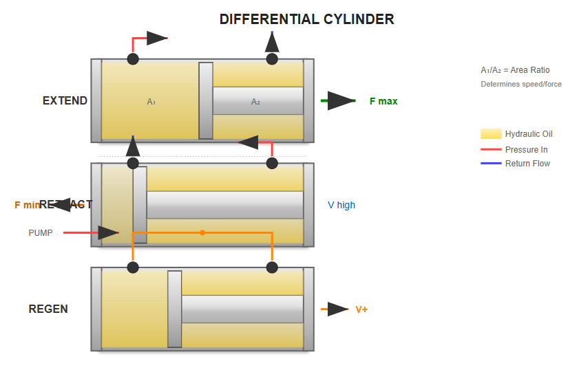
Full piston area acts to produce maximum force with standard speed
Reduced effective area creates higher speed with lower force
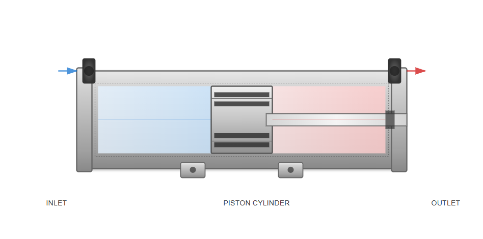
The effectiveness of any cylinder hydraulic depends critically on its sealing system. Modern seal designs incorporate advanced materials and geometries to minimize friction while preventing leakage.
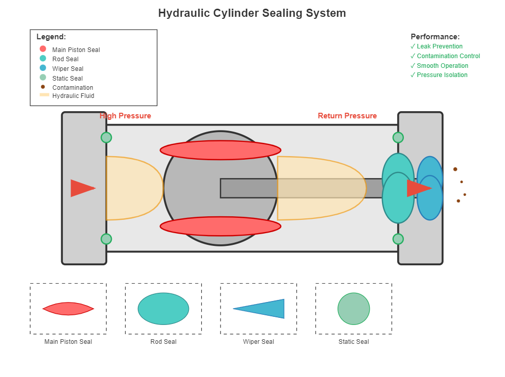
Separate the two pressure chambers, preventing internal leakage while allowing smooth piston movement. Materials are selected based on pressure, temperature, and fluid compatibility.
Prevent external leakage around the piston rod and exclude contaminants from entering the cylinder. These seals must withstand dynamic movement while maintaining effective sealing.
Provide additional protection against ingress of foreign materials that could damage internal components. These seals wipe the rod clean as it extends and retracts.
Positioned at interfaces between stationary components to prevent external leakage and maintain system pressure. These include O-rings, gaskets, and other static sealing elements.
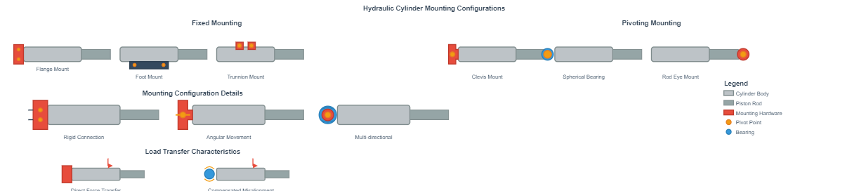
The mounting method significantly influences cylinder hydraulic performance and longevity. Proper mounting selection ensures efficient force transmission while minimizing side loads that could cause premature wear or binding.
Provide rigid attachment to the machine structure, suitable for applications where the cylinder axis remains constant relative to the machine frame.
Provide strong, rigid mounting with flange at cylinder end
Attach to cylinder barrel with base plate for stable mounting
Pivot points on cylinder barrel for controlled movement
Accommodate angular movement as the cylinder extends and retracts, essential in applications where the load path varies throughout the stroke.
U-shaped brackets allowing pivotal movement around a pin
Allow multi-directional movement for misalignment compensation
Pivoting attachment at rod end for dynamic applications
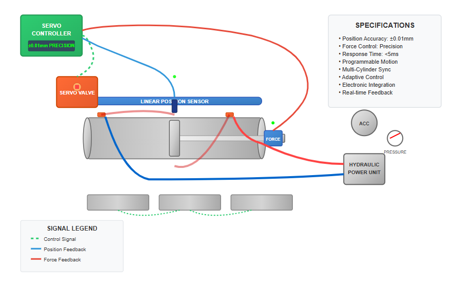
Modern cylinder hydraulic technology increasingly incorporates servo control for precise positioning and force control. Servo-hydraulic cylinders integrate position or force feedback sensors with sophisticated control valves to achieve exceptional accuracy and repeatability.
These systems find application in testing equipment, flight simulators, and precision manufacturing processes where conventional hydraulic cylinders cannot provide adequate control resolution.
The integration of electronic control with cylinder hydraulic systems enables advanced features such as synchronized multi-cylinder operation, programmable motion profiles, and adaptive control algorithms.
The evolution of cylinder hydraulic technology includes the integration of various sensors directly into the cylinder structure, enabling intelligent operation and condition monitoring.
Ranging from simple proximity switches to high-resolution linear transducers, providing real-time feedback on cylinder position for precise control.
Monitor operating conditions and can detect abnormal situations such as excessive loads or system malfunctions before they cause damage.
Track thermal conditions within the cylinder hydraulic, enabling predictive maintenance strategies and preventing damage from overheating.
Incorporate accelerometers to monitor vibration patterns, providing insights into system health and identifying potential problems before failures occur.
Modern smart cylinders integrate multiple sensors with onboard processing capabilities to provide comprehensive condition monitoring and performance data. This enables predictive maintenance, improves system efficiency, and reduces downtime.
Contemporary cylinder hydraulic manufacturing employs advanced materials and processes to enhance performance and durability. These innovations have significantly extended service life while improving efficiency.
Carbon fiber-reinforced plastics offer exceptional strength-to-weight ratios for piston rods and cylinder tubes, though cost considerations currently limit their use to specialized applications where weight reduction is critical.
Modern manufacturing techniques have revolutionized cylinder production, enabling tighter tolerances and improved performance characteristics:
Contamination represents a primary cause of cylinder hydraulic failure, making effective filtration and contamination control essential for reliable operation. Even small particles can cause significant damage to precision components.
Protect downstream components by filtering fluid under pressure, typically installed between the pump and system components.
Remove contaminants picked up during system operation before fluid returns to the reservoir for recirculation.
Independent systems that continuously filter fluid from the reservoir, maintaining cleanliness without interrupting operation.
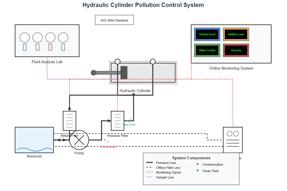
Proper fluid maintenance extends beyond filtration to include monitoring fluid condition through regular sampling and analysis:
Quantifies contamination levels to ISO cleanliness standards
Detects moisture that can cause corrosion and fluid degradation
Monitors depletion of critical additives that protect system components
Ensures fluid maintains proper viscosity across operating temperatures
Advanced cylinder hydraulic systems may incorporate online monitoring systems that continuously assess fluid condition and alert operators to deteriorating conditions before they cause damage.
The versatility of cylinder hydraulic technology enables applications across virtually every industrial sector, providing the power density and reliability required for demanding operations.
In manufacturing, hydraulic cylinders power presses, injection molding machines, and material handling equipment, providing precise force control and reliable operation.
The construction industry relies on cylinder hydraulic systems for excavators, cranes, and concrete pumping equipment, where high forces and reliable operation in harsh environments prove essential.
Agricultural machinery extensively employs hydraulic cylinders for implement control, steering systems, and harvesting mechanisms, providing robust performance in challenging environments.
Mobile hydraulic systems present unique challenges for cylinder hydraulic design due to size constraints, environmental exposure, and varying operating conditions. These applications demand compact designs that maximize force output within limited space envelopes.
Robust construction is essential to withstand shock loads and vibration inherent in mobile applications, while specialized coatings and sealing systems protect against environmental contaminants.
Modern mobile systems often incorporate load-sensing hydraulics to optimize efficiency and reduce heat generation, extending component life and reducing operating costs.
Safety remains paramount in cylinder hydraulic applications, with various design features and operational practices ensuring safe operation even under extreme conditions.
Prevent over-pressurization that could cause catastrophic failure by diverting excess fluid back to the reservoir.
Provide last-resort protection against extreme pressure events, rupturing at predefined pressure levels to prevent cylinder damage.
Prevent uncontrolled cylinder movement in the event of hose failure or other system malfunctions, often utilizing check valves with pilot operation.
Prevent damaging impacts at stroke ends, protecting both the cylinder and the machinery it operates.
Regular inspection and maintenance programs identify potential problems before they compromise safety:
Detect external leakage, damaged components, or mounting problems that could affect safety.
Verifies system integrity and proper operation of safety valves under controlled conditions.
The cylinder hydraulic maintenance schedule should consider factors such as duty cycle, operating environment, and criticality of the application.
Maintaining records of inspections, maintenance, and repairs provides valuable data for optimizing safety and reliability.
The design and manufacture of cylinder hydraulic systems follow various international standards ensuring interchangeability, safety, and performance across different manufacturers and applications.
Develops global standards for hydraulic components, ensuring international compatibility and performance.
Relevant Standards:
Develops standards primarily for the North American market, focusing on interchangeability and performance.
Relevant Standards:
Adherence to international standards provides numerous benefits for both manufacturers and users of hydraulic cylinders:
From basic actuation to precision control systems, hydraulic cylinders continue to evolve as essential components in modern industrial machinery, offering unparalleled power density and reliability across countless applications.