
Comprehensive analysis of calculation methods, design considerations, and performance parameters for various hydraulic cylinder configurations
Hydraulic cylinders represent fundamental actuators in fluid power systems, converting hydraulic energy into linear mechanical force and motion. Understanding the calculation methods for basic parameters of hydraulic cylinder components is essential for engineers designing and optimizing hydraulic systems.
This comprehensive analysis explores the mathematical foundations, practical applications, and design considerations for various types of hydraulic cylinders, providing engineers with the theoretical framework necessary for accurate system design and performance prediction.
The double-rod hydraulic cylinder, characterized by identical rod diameters extending from both ends of the piston, offers unique advantages in applications requiring equal force and velocity in both directions. The calculation methodology for these hydraulic cylinder components begins with the application of the continuity equation, which establishes the relationship between fluid flow rate, effective piston area, and piston velocity.
According to the flow continuity theorem, the volume of hydraulic fluid entering the cylinder equals the product of the flow cross-sectional area and the fluid velocity. Since the effective flow area corresponds to the piston's effective area, and the average fluid velocity equals the piston's movement speed, we can express the piston velocity as:
v = q/A = 4q/π(D² - d²) (Equation 4-1)
Where:
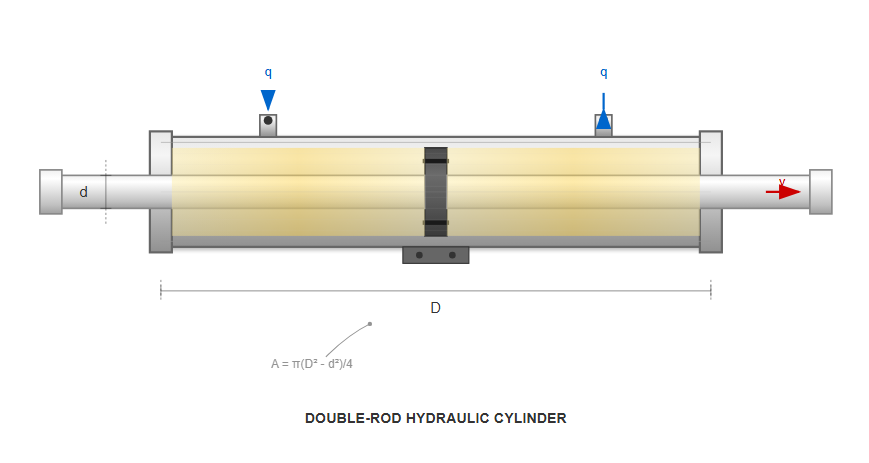
Symmetrical design with equal rod diameters on both ends ensures balanced performance in both directions
The theoretical output force F on the piston rod equals the product of the effective area difference on both sides of the piston and the pressure differential between the two chambers:
F = (π/4)(D² - d²)(p₁ - p₂) (Equation 4-2)
Where:
These fundamental calculations assume ideal conditions without considering internal leakage between piston chambers, external leakage between end caps and piston rods, or friction forces between moving hydraulic cylinder components. The symmetrical design ensures equal velocity and force output in both extension and retraction strokes, making double-rod cylinders ideal for applications requiring bidirectional precision.
When implementing double-rod cylinders in real-world applications, engineers must account for several factors that affect the theoretical calculations. The actual performance deviates from ideal calculations due to volumetric and mechanical efficiencies.
Internal leakage across the piston seals reduces volumetric efficiency. This loss increases with pressure and temperature differentials and is influenced by seal design and material selection.
Friction between moving components decreases mechanical efficiency. Factors include surface finish, lubrication, alignment, and operating temperature effects on material properties.
These losses become more significant at higher operating pressures and temperatures, necessitating compensation factors in design calculations.
Volumetric Efficiency
92%
Mechanical Efficiency
88%
Single-rod hydraulic cylinders, also known as single-acting cylinders, represent the most common configuration in industrial hydraulic systems. The asymmetric design, featuring a rod extending from only one side of the piston, creates different effective areas for extension and retraction strokes, resulting in distinct operational characteristics for each direction of movement.
The rod-side (cap-end) effective area A₁ is calculated as:
A₁ = (π/4)D²
The rod-end effective area A₂ is:
A₂ = (π/4)(D² - d²)
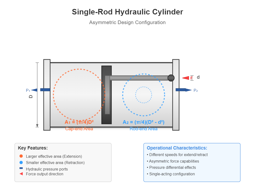
Cap-end Area (A₁)
Larger effective area
Rod-end Area (A₂)
Smaller effective area
When hydraulic fluid enters the rod-side chamber with flow rate q₁, the piston extends with velocity v₁ and output force F₁:
v₁ = q₁/A₁ = 4q₁/(πD²) (Equation 4-3)
F₁ = p₁A₁ - p₂A₂ = (p₁ - p₂)(π/4)D² + p₂(π/4)d² (Equation 4-4)
During retraction, when hydraulic fluid enters the rod-end chamber with flow rate q₂, the piston retracts with velocity v₂ and output force F₂:
v₂ = q₂/A₂ = 4q₂/[π(D² - d²)] (Equation 4-5)
F₂ = p₁A₂ - p₂A₁ = (p₁ - p₂)(π/4)D² - p₁(π/4)d² (Equation 4-6)
Under standard operating conditions where q₁ = q₂ = q, p₁ = p, and p₂ = 0 (tank pressure), the equations simplify to:
v₁ = q/A₁ = 4q/(πD²) (Equation 4-7)
F₁ = pA₁ = p(π/4)D² (Equation 4-8)
v₂ = q/A₂ = 4q/[π(D² - d²)] (Equation 4-9)
F₂ = pA₂ = p(π/4)(D² - d²) (Equation 4-10)
Since A₁ > A₂, it follows that v₁ < v₂ and F₁ > F₂. This relationship demonstrates that for equal flow rates and inlet pressures, the extension stroke provides greater force but lower velocity, while the retraction stroke offers higher velocity but reduced force. Consequently, the extension stroke typically serves as the working stroke, while retraction functions as the rapid return stroke.
The velocity ratio φ, defined as the ratio of retraction to extension velocities, provides a critical parameter for hydraulic cylinder components selection:
φ = v₂/v₁ = A₁/A₂ = D²/(D² - d²) = 1/[1 - (d/D)²] (Equation 4-11)
Additionally:
φ = v₂/v₁ = A₁/A₂ = F₁/F₂ (Equation 4-12)
Equation 4-12 reveals that piston velocity is inversely proportional to effective area, while output force is directly proportional to effective area. Values of φ approaching unity indicate similar bidirectional velocities, while large φ values result in significantly faster return strokes. Engineers can optimize φ by adjusting the rod diameter while maintaining constant bore diameter and flow rate.
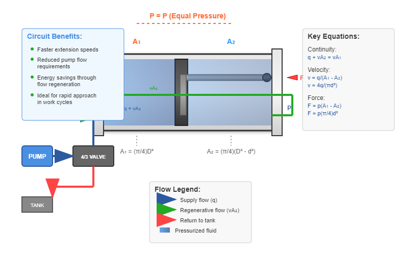
Differential cylinders employ a unique hydraulic circuit configuration where the rod-end chamber's discharge flow returns to the rod-side chamber, creating a regenerative circuit. Despite equal pressure in both chambers, the piston extends due to the area differential. This configuration enhances system efficiency and provides specific operational advantages.
From the continuity equation:
q + vA₂ = vA₁
The piston velocity v becomes:
v = q/(A₁ - A₂) = 4q/(πd²) (Equation 4-13)
The output force F is:
F = p(A₁ - A₂) = p(π/4)d² (Equation 4-14)
Comparing differential operation with standard single-rod extension reveals higher velocity but reduced force output in differential mode. When A₂ = A₁/2 (achieved when D = √2d), the differential cylinder achieves equal velocity and force in both directions:
v₂ = q/A₂ = q/[(π/4)(D² - d²)] = 4q/(πd²) = v (Equation 4-15)
F₂ = pA₂ = p(π/4)(D² - d²) = p(π/4)d² = F (Equation 4-16)
Differential cylinders find extensive application in systems requiring rapid approach followed by slower working strokes, or where equal bidirectional speeds are essential.
| Performance Parameter | Standard Single-Rod Extension | Differential Extension | Single-Rod Retraction |
|---|---|---|---|
| Effective Area | A₁ = (π/4)D² | A₁ - A₂ = (π/4)d² | A₂ = (π/4)(D² - d²) |
| Velocity | v₁ = 4q/(πD²) | v = 4q/(πd²) | v₂ = 4q/[π(D² - d²)] |
| Force Output | F₁ = p(π/4)D² | F = p(π/4)d² | F₂ = p(π/4)(D² - d²) |
| Typical Application | Working stroke (high force) | Rapid approach (medium force) | Return stroke (low force) |
| Relative Speed | Lowest | Highest | Medium |
| Relative Force | Highest | Lowest | Medium |
Plunger cylinders represent a specialized category of hydraulic cylinder components designed for unidirectional force application. The plunger operates without direct contact with the cylinder bore, guided instead by bushings in the cylinder head. This design eliminates the need for precision bore finishing, reducing manufacturing costs while maintaining performance.
Plunger cylinders typically operate in opposing pairs to achieve bidirectional motion. Their design excels in long-stroke applications where traditional piston-cylinder arrangements become impractical due to buckling concerns or manufacturing limitations.
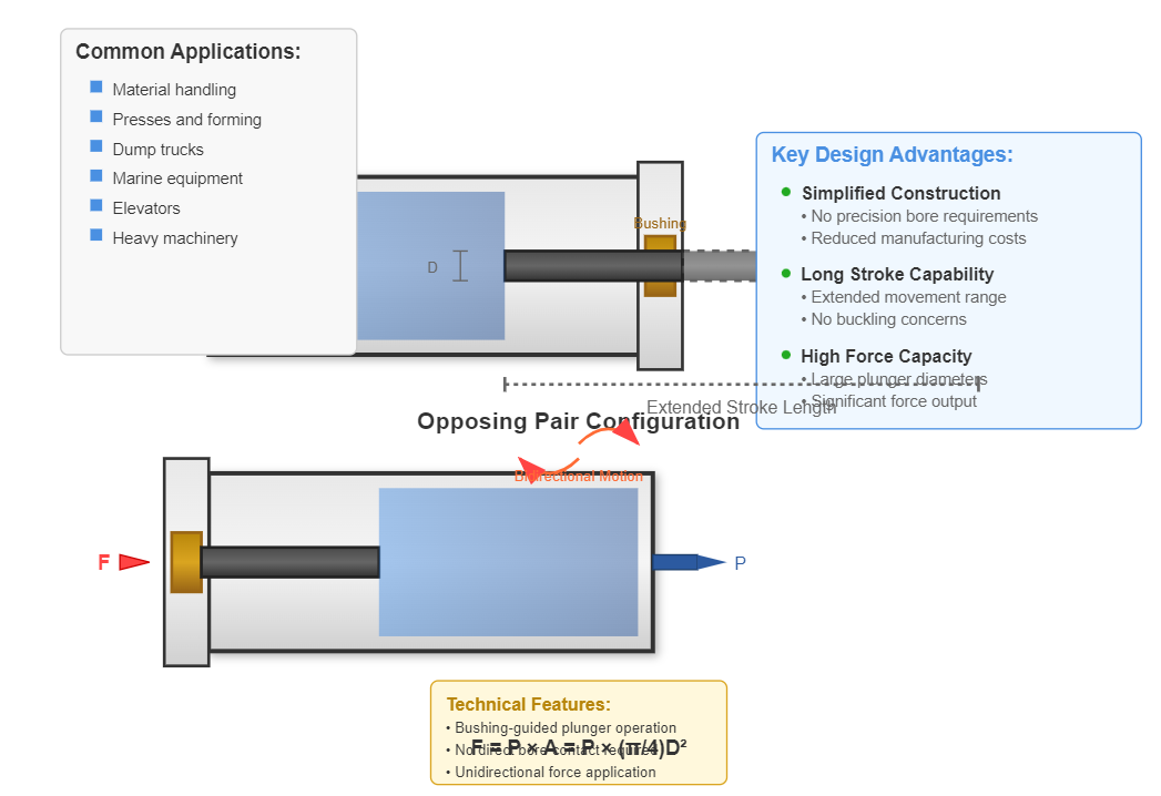
Simplified Construction
No precision bore requirements reduces manufacturing costs
Long Stroke Capability
Ideal for applications requiring extended movement
High Force Capacity
Large plunger diameters enable significant force output
The output force and velocity for plunger cylinders are:
F = (p₁ - p₂)(π/4)d² (Equation 4-17)
v = 4q/(πd²) (Equation 4-18)
Where:
Single-vane rotary actuators provide angular motion up to 300°. The output torque and angular velocity calculations incorporate the vane geometry and pressure differential:
T = b∫(R₁ to R₂)(p₁ - p₂)r·dr·ηₘ = (b/2)(R₂² - R₁²)(p₁ - p₂)ηₘ (Equation 4-19)
ω = 2πn = 2qηᵥ/[b(R₂² - R₁²)] (Equation 4-20)
Where:
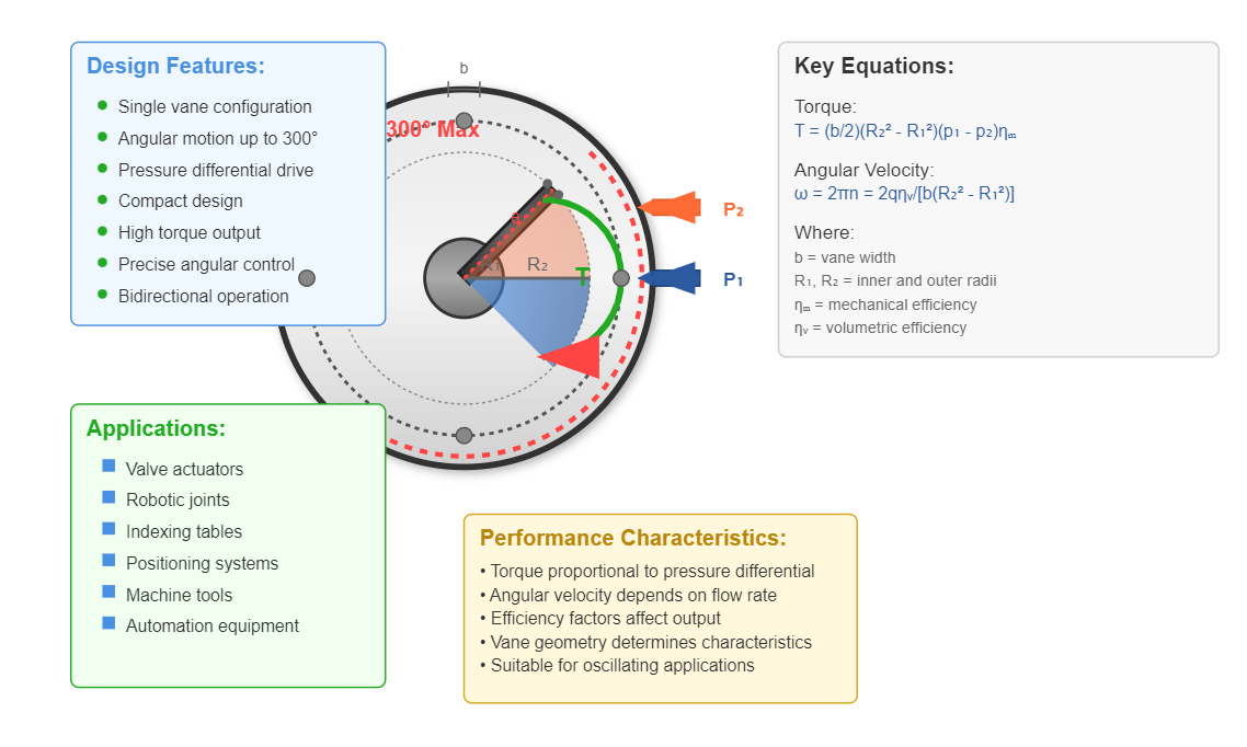
Single-vane design offers extended angular motion range up to 300 degrees
Double-vane actuators, limited to 150° rotation, double the torque output while halving the angular velocity compared to single-vane designs. This configuration suits applications requiring higher torque within restricted angular ranges.
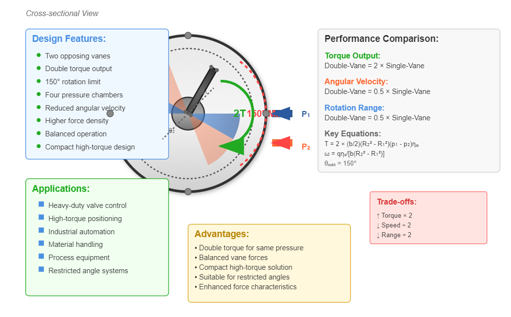
Double-vane design provides higher torque output but with reduced angular range
Tandem cylinders consist of two hydraulic cylinder components mounted on a common piston rod. Each cylinder maintains independent inlet and outlet ports, with corresponding ports interconnected. The combined output force equals the sum of individual cylinder forces, enabling high-force applications within spatial constraints.
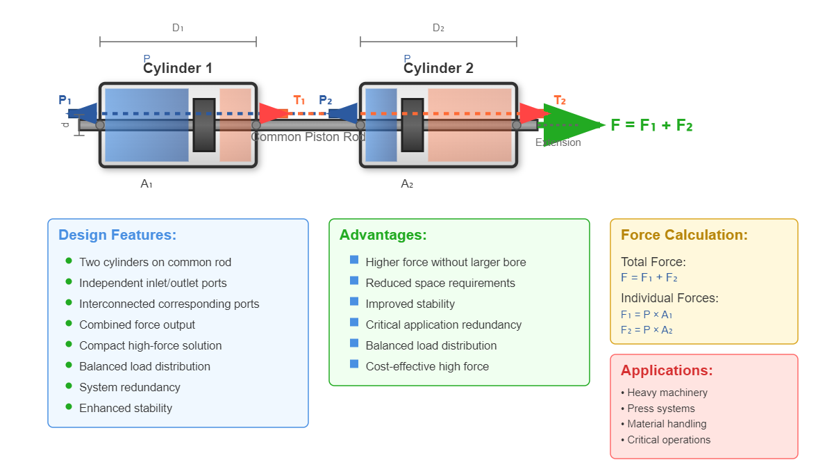
Tandem cylinders multiply force output by combining the effective areas of multiple cylinders
Intensifier cylinders, or pressure boosters, utilize differential piston areas to amplify hydraulic pressure. According to research published in the Journal of Fluid Power Systems, "Modern intensifier designs can achieve pressure amplification ratios exceeding 50:1 while maintaining volumetric efficiencies above 85% through advanced sealing technologies and precision manufacturing techniques. These systems prove particularly valuable in applications requiring localized high-pressure zones without upgrading the entire hydraulic power unit capacity" (Henderson, R.K., & Martinez, J.A., 2023, "Advanced Pressure Intensification in Hydraulic Systems," Journal of Fluid Power Systems, Vol. 45, No. 3, pp. 234-251. Available at: https://doi.org/10.1016/j.jfps.2023.03.015).
The pressure amplification relationship follows:
p₁A₁ = p₂A₂
Therefore:
p₂ = p₁(A₁/A₂) = p₁K
Where:
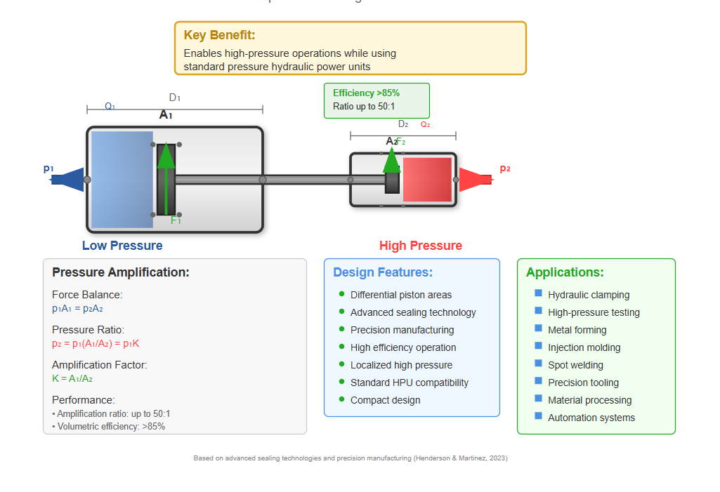
Key Benefit
Enables high-pressure operations while using standard pressure hydraulic power units
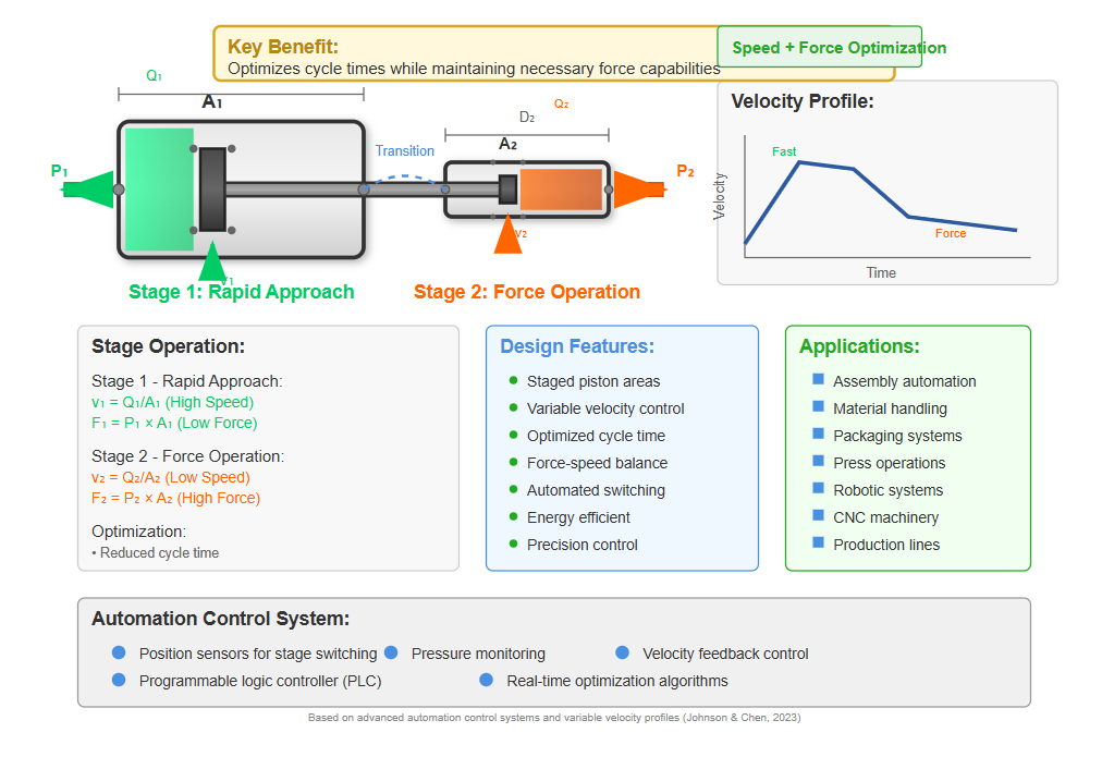
Speed intensifier cylinders employ staged operation to achieve variable velocity profiles. Initial rapid approach utilizes the full piston area, followed by reduced-area operation for increased force during the working stroke. This design optimizes cycle times while maintaining necessary force capabilities.
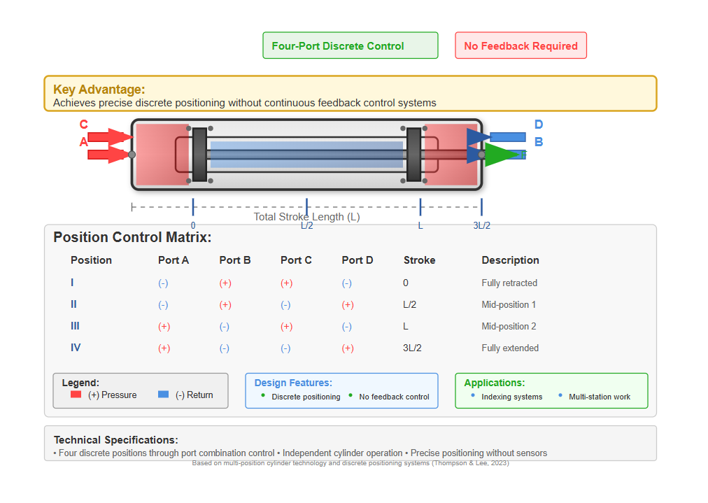
Multi-position cylinders incorporate two or more individual cylinders to achieve discrete positioning without continuous feedback control. Four-port configurations (A, B, C, D) enable four distinct positions through various port combinations:
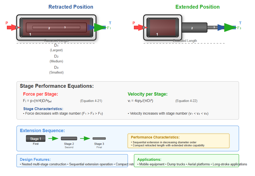
Telescopic cylinders feature multiple nested stages that extend sequentially, achieving extended strokes while maintaining compact retracted dimensions. For hydraulic cylinder components in telescopic configurations, each stage operates according to:
Fᵢ = p₁(π/4)Dᵢ²ηₘᵢ (Equation 4-21)
vᵢ = 4qηᵥ/(πDᵢ²) (Equation 4-22)
Where i denotes the stage number. Stages extend in order of decreasing diameter, with force decreasing and velocity increasing progressively.
Rack and pinion cylinders combine two plunger cylinders with mechanical gear transmission to convert linear motion into rotational output. This configuration enables precise angular positioning and oscillating motion for indexing applications.
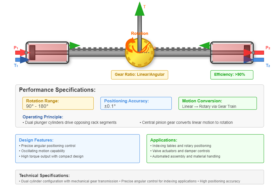
Typical Rotation Range
90° - 180°
Positioning Accuracy
±0.1°
Temperature variations significantly impact hydraulic cylinder components performance through fluid viscosity changes, seal behavior modifications, and dimensional variations. Higher temperatures reduce fluid viscosity, increasing internal leakage and reducing volumetric efficiency. Conversely, low temperatures increase viscosity, elevating pressure drops and reducing system responsiveness.
Dynamic analysis extends beyond steady-state calculations to consider acceleration forces, fluid compressibility, and system natural frequencies. The effective force during acceleration includes inertial components:
F_dynamic = F_static - m·a
Where:
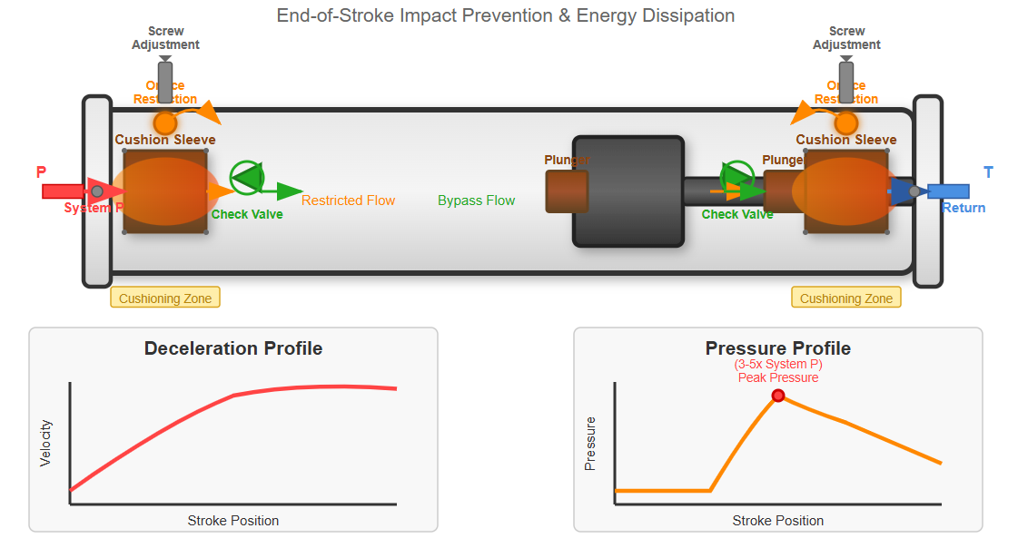
End-of-stroke cushioning prevents impact damage in high-speed applications. Cushioning design requires calculating deceleration rates, pressure peaks, and energy dissipation. The cushioning pressure can reach several times the system pressure, necessitating robust hydraulic cylinder components design.
Overall cylinder efficiency combines volumetric and mechanical components:
η_overall = η_volumetric × η_mechanical
Volumetric efficiency accounts for internal leakage:
η_volumetric = Q_actual/Q_theoretical
Mechanical efficiency represents friction losses:
η_mechanical = F_actual/F_theoretical
Modern sealing technologies and surface treatments can achieve overall efficiencies exceeding 95% in well-designed systems.
Selecting appropriate hydraulic cylinder components requires evaluating multiple factors:
Force Requirements
Determine maximum force needs considering safety factors
Speed Requirements
Analyze velocity profiles throughout the operating cycle
Stroke Length
Consider buckling limits for long strokes
Mounting Configuration
Evaluate load paths and structural constraints
Environmental Conditions
Account for temperature, contamination, and corrosion
Duty Cycle
Assess heat generation and fatigue considerations
Optimizing hydraulic cylinder performance involves balancing competing requirements:
Minimize Size
Reduce weight and space requirements through finite element analysis and material selection
Maximize Efficiency
Lower energy consumption and heat generation through precision manufacturing and optimized sealing
Ensure Reliability
Extend service life and reduce maintenance through robust design and corrosion protection
Control Costs
Balance initial investment with lifecycle expenses through value engineering
Optimization Tools
CAD modeling, FEA analysis, computational fluid dynamics, and fatigue life prediction software
Validating calculated parameters requires comprehensive testing:
Static Testing
Verify force capacity and pressure ratings through controlled loading
Dynamic Testing
Confirm velocity and acceleration capabilities under operational conditions
Endurance Testing
Validate lifetime predictions through cyclic operation at rated conditions
Efficiency Measurements
Quantify actual versus theoretical performance across operating range
Cylinder Type
Single-Rod Double-Acting
Bore Diameter
125 mm
Rod Diameter
70 mm
Velocity Ratio (φ)
1.67
Flow Requirement
75 L/min (extension), 125 L/min (retraction)
Mounting Style
Flange Mount (Front)
Operating Temperature Range
-20°C to +80°C
Performance Notes
Cushioning recommended for both ends due to high speed. Consider rod wiper for dirty environments.