
A comprehensive technical overview of the fundamental design, components, and operational principles of hydraulic cylinders in fluid power systems.
The hydraulic cylinder represents one of the most fundamental actuators in fluid power systems, converting hydraulic energy into linear mechanical force and motion. Understanding the typical structures and configurations of hydraulic cylinder parts is essential for engineers, technicians, and maintenance professionals working in various industrial applications.
"Hydraulic cylinders serve as the workhorses of industrial automation, providing the precise linear motion and force required in countless manufacturing and mobile equipment applications."
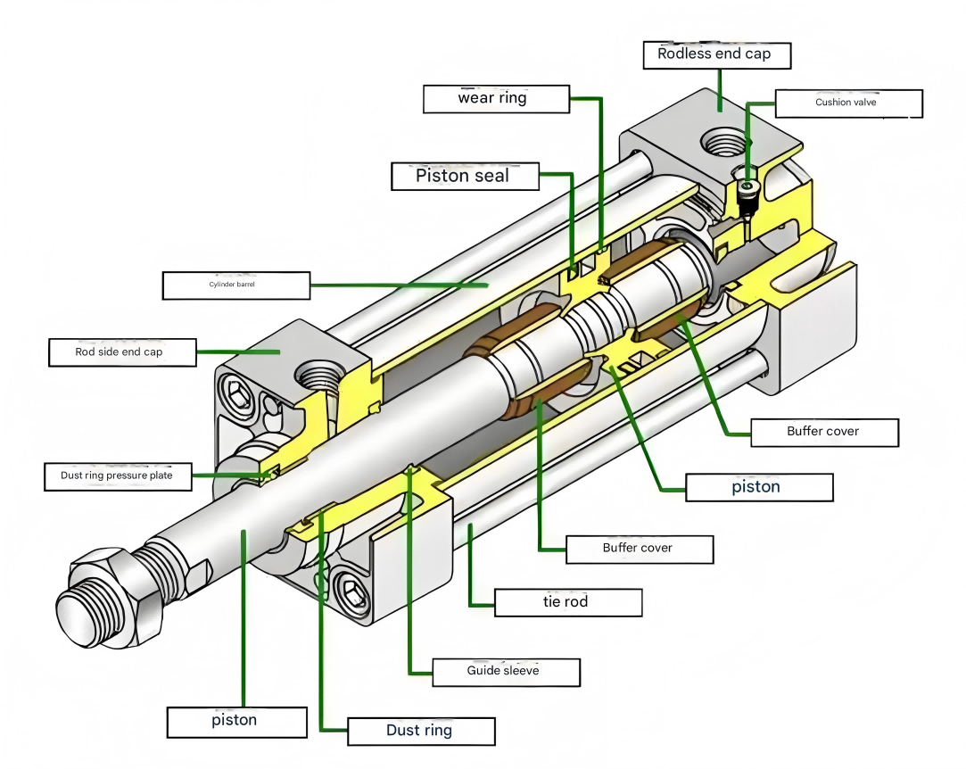
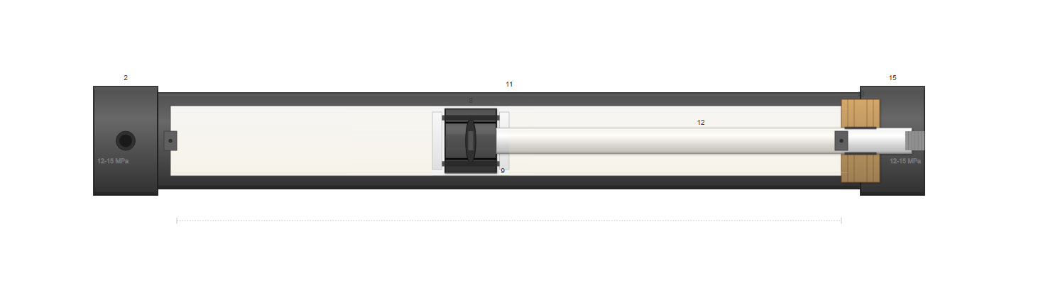
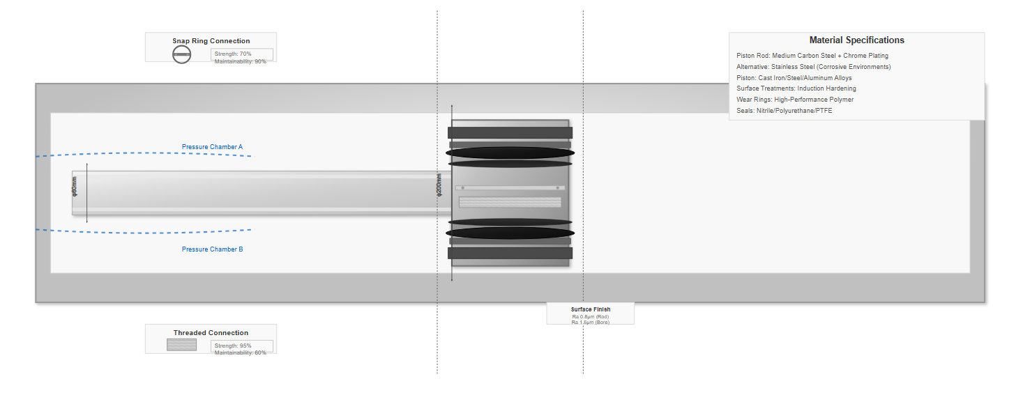
A typical double-acting single-rod piston hydraulic cylinder, as illustrated in engineering references, exemplifies the standard configuration found in industrial machinery. The essential hydraulic cylinder parts include the cylinder bottom (component 2), piston (component 8), cylinder barrel (component 11), piston rod (component 12), guide sleeve (component 13), and end cap (component 15). This particular design configuration has become prevalent in engineering machinery due to its optimal balance of functionality, reliability, and maintainability.
The structural characteristic that distinguishes this design is the snap ring connection between the piston and piston rod, which significantly facilitates assembly and disassembly procedures. The support ring (component 9), manufactured from polytetrafluoroethylene (PTFE) or similar wear-resistant materials, minimizes friction forces during operation.
The guide sleeve serves a critical function in preventing piston rod deflection during movement, thereby protecting the sealing elements from premature wear. Both ends of the cylinder incorporate throttling-type cushioning devices, effectively reducing impact forces and noise generation when the piston approaches its end positions. These hydraulic cylinders typically operate within pressure ranges of 12-15 MPa (1,740-2,175 PSI), making them suitable for a wide range of industrial applications.
12-15 MPa (1,740-2,175 PSI)
0.1-1 m/s (3.9-39.4 in/s)
-20°C to +80°C (-4°F to +176°F)
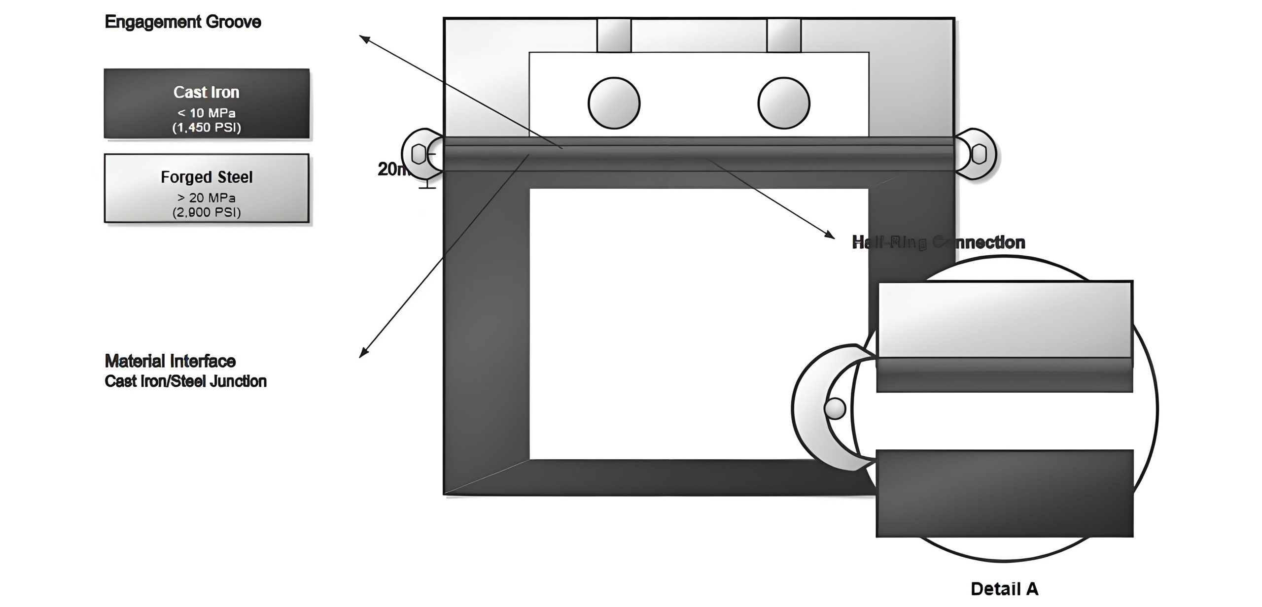
The structural configuration of cylinder barrels and heads fundamentally depends on the materials employed and the operational requirements. Material selection follows established pressure criteria: cast iron for pressures below 10 MPa (1,450 PSI), seamless steel tubing for pressures up to 20 MPa (2,900 PSI), and cast or forged steel for pressures exceeding 20 MPa. These material choices directly influence the structural design and connection methods employed.
The flange connection structure represents one of the most common configurations for joining hydraulic cylinder parts. This design offers simplicity in both manufacturing and assembly processes, with straightforward disassembly procedures for maintenance. However, the flange connection results in larger external dimensions and increased weight, making it particularly suitable for cast iron cylinder constructions where these factors are less critical.
The half-ring connection structure provides an alternative approach, available in both external and internal configurations. This connection method offers improved compactness compared to flange connections while maintaining adequate strength for medium-pressure applications. The design consists of two semi-circular rings that engage with corresponding grooves in the cylinder barrel and head, secured by appropriate fasteners.
Common in heavy-duty applications where ease of maintenance is prioritized over size and weight considerations.
Provides compact design with good strength characteristics for medium-pressure applications.
| Connection Type | Strength | Maintainability | Cost |
|---|---|---|---|
| Snap Ring |
|
|
|
| Threaded |
|
|
|
Modern piston designs incorporate wear rings and guide bands to minimize metal-to-metal contact, extending service life.
The piston and piston rod assembly represents the primary moving element within the hydraulic cylinder system. Various connection methods between these hydraulic cylinder parts have been developed to address different operational requirements and maintenance considerations. The snap ring connection method, as mentioned earlier, provides excellent serviceability while maintaining structural integrity under normal operating conditions.
Thread connections offer another approach, providing high strength and reliability but requiring more complex assembly procedures. The selection between connection methods depends on factors including operating pressure, frequency of maintenance, and overall system design requirements.
Modern designs often incorporate features such as wear rings and guide bands to minimize metal-to-metal contact, extending service life and improving operational efficiency. These components reduce friction and prevent galling between moving parts, particularly important in high-cycle applications.
Sealing technology represents a critical aspect of hydraulic cylinder design, directly impacting efficiency, reliability, and service life. Gap sealing, while simple in concept, relies on precise machining tolerances to maintain minimal clearances between moving hydraulic cylinder parts. This method, though limited in effectiveness, finds application in low-pressure situations or as a secondary sealing measure.
Friction ring sealing employs metallic or non-metallic rings that create a controlled friction interface between moving components. These rings, often manufactured from cast iron or bronze alloys, provide effective sealing while accommodating some degree of wear through their self-adjusting characteristics. The friction ring design must balance sealing effectiveness against power losses due to friction.
"Modern elastomeric sealing systems in hydraulic cylinders have achieved leakage rates below 0.1 ml/hour under pressures up to 35 MPa, representing a significant advancement in sealing technology. These improvements result from advances in material science, particularly in polyurethane and PTFE-based compounds, combined with optimized seal geometry designs that minimize extrusion while maintaining adequate contact pressure."
Johnson, M.K., & Anderson, P.L., 2023
O-ring and V-ring seals utilize the elastic properties of rubber or plastic materials to create effective barriers against fluid leakage. These sealing elements, available in various cross-sectional configurations, provide reliable performance with automatic wear compensation capabilities. Their versatility allows application between cylinder barrel and piston, piston and piston rod, and cylinder barrel and cylinder head interfaces.
Elastomeric seals providing reliable performance across wide pressure ranges
Prevent contamination of hydraulic fluid and seal damage
For the externally extending portion of the piston rod, contamination prevention becomes paramount. External contaminants can compromise seal integrity and contaminate hydraulic fluid, leading to accelerated wear of hydraulic cylinder parts. Therefore, wiper seals or scrapers are typically installed on the rod-side of the main seal, oriented to remove contaminants from the rod surface during retraction.
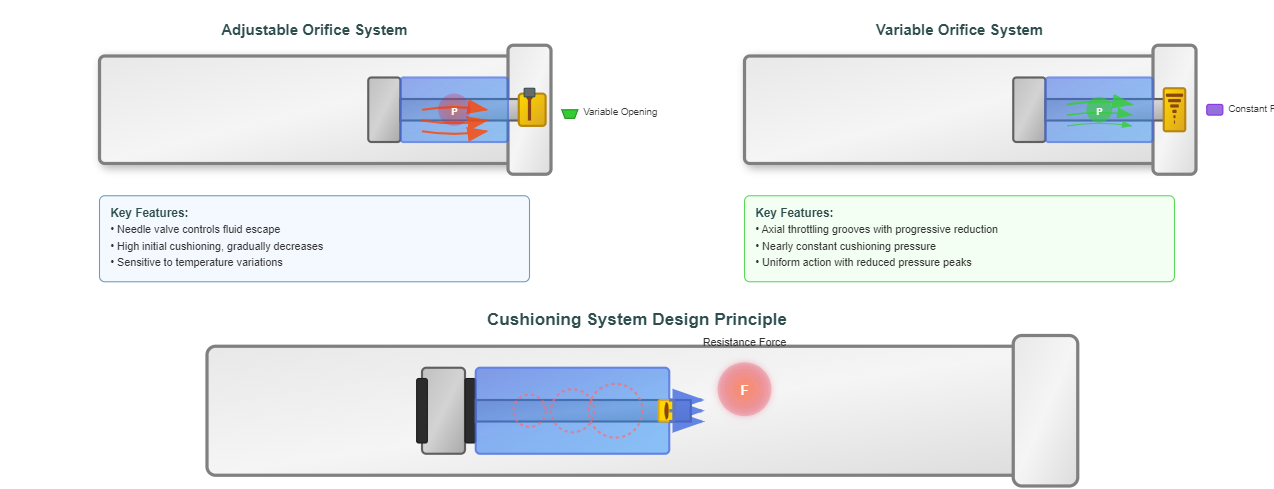
Cushioning devices trap fluid between piston and cylinder head, creating resistance that decelerates moving mass.
Cushioning devices in hydraulic cylinders operate on the principle of trapping a volume of fluid between the piston and cylinder head as the piston approaches its stroke end. This trapped fluid must escape through a restricted orifice or passage, creating substantial resistance that decelerates the moving mass, preventing destructive impact between hydraulic cylinder parts.
Two primary cushioning configurations dominate modern designs: adjustable orifice systems and variable orifice systems. Each offers distinct advantages and operational characteristics suited to different application requirements.
For rectangular groove cross-sections with conical longitudinal profiles, the system can maintain nearly constant cushioning pressure throughout the deceleration phase. This characteristic results from the parabolic relationship between throttling area and piston position, optimally matching the kinetic energy dissipation requirements.
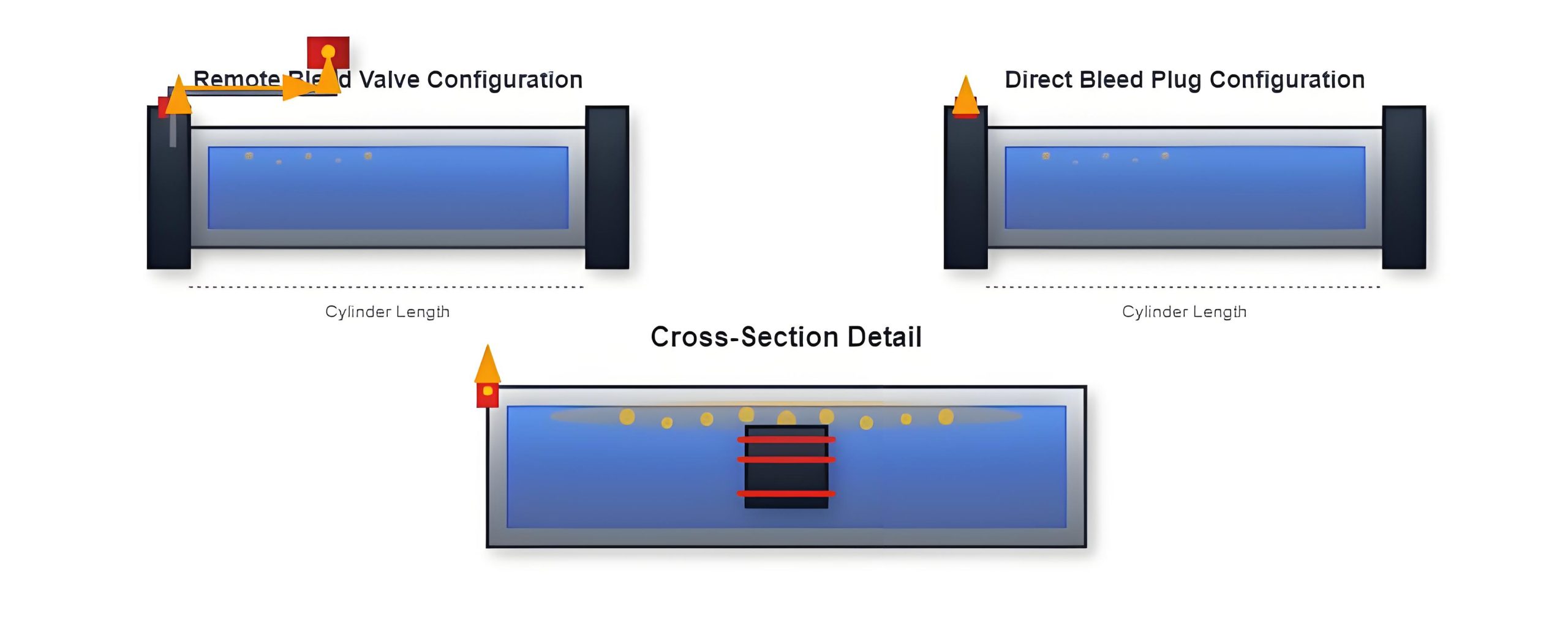
Air bleeding devices constitute essential hydraulic cylinder parts for maintaining optimal system performance. Air entrainment in hydraulic fluid, whether from initial filling, maintenance operations, or long-term storage, accumulates at the highest points within the cylinder. This trapped air significantly impacts operational characteristics, causing low-speed crawling, startup impacts, and reduced positioning accuracy during direction changes.
Two primary air bleeding configurations address this requirement:
Incorporates an air bleed port at the cylinder head's highest elevation, connected via extended piping to a remotely located bleed valve. This arrangement allows air bleeding operations without direct access to the cylinder head, advantageous in installations with limited accessibility.
Employs a bleed plug installed directly at the cylinder head's highest point. This simpler approach requires direct access for bleeding operations but eliminates extended piping and potential leak points. Both configurations operate through manual activation during commissioning or maintenance, requiring several complete cylinder strokes to ensure complete air evacuation.
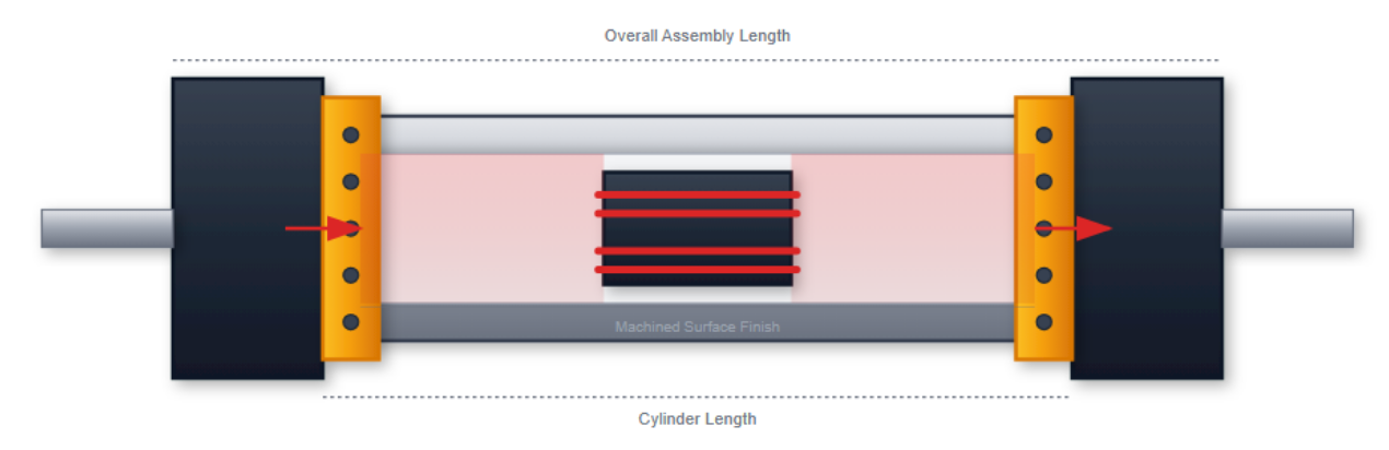
Manufactured from seamless steel tubing undergoing honing operations to achieve surface finishes typically below 0.4 μm Ra, essential for proper seal function and minimal friction.
The honing process creates a characteristic cross-hatch pattern that retains lubricating oil while providing optimal sealing surface characteristics.
Require exceptional straightness, surface finish, and wear resistance. Surface treatments such as induction hardening, chrome plating, or ceramic coating enhance wear resistance and corrosion protection.
The rod surface finish typically achieves 0.2 μm Ra or better, critical for seal life and leakage prevention.
May be manufactured from cast iron, steel, or aluminum alloys, depending on application requirements. Cast iron pistons offer good wear characteristics and damping properties.
The piston design must accommodate seal grooves, wear ring installation, and potential cushioning spear integration while maintaining structural integrity under maximum operating pressures.
Modern hydraulic cylinder design increasingly employs computational tools for optimization of hydraulic cylinder parts. Finite element analysis (FEA) enables detailed stress analysis of critical components under various loading conditions. Computational fluid dynamics (CFD) assists in optimizing cushioning chamber geometry and flow passages for improved deceleration characteristics.
The integration of sensor technology into hydraulic cylinders enables real-time monitoring of position, pressure, and temperature parameters. Smart cylinders incorporating integrated electronics provide diagnostic capabilities, predictive maintenance alerts, and enhanced control system integration. These advancements transform traditional hydraulic cylinders into intelligent actuators capable of self-monitoring and performance optimization.
Real-time monitoring of pressure, temperature, and position
Remote diagnostics and predictive maintenance capabilities
Biodegradable fluid compatibility and energy-efficient operation
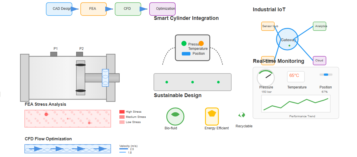
Advanced simulation tools enable engineers to optimize hydraulic cylinder designs before physical prototyping, reducing development time and improving performance characteristics. Finite Element Analysis (FEA) helps identify stress concentrations, while Computational Fluid Dynamics (CFD) optimizes fluid flow paths.
Seal system optimization continues to advance through material science developments and improved understanding of tribological mechanisms. Low-friction seal designs reduce energy consumption while maintaining sealing effectiveness.
Temperature-resistant materials extend operational ranges, while specialized compounds address specific media compatibility requirements. The development of biodegradable hydraulic fluids necessitates corresponding seal material adaptations to maintain system reliability.
Different industries impose unique requirements on hydraulic cylinder design and construction. Mobile equipment applications prioritize weight reduction and compact design while maintaining durability under harsh environmental conditions. Industrial machinery emphasizes precision, repeatability, and extended service intervals.
Heavy-duty cylinders with robust construction, high force capabilities, and resistance to contamination.
Precision cylinders with tight tolerances, smooth operation, and consistent performance.
Lightweight designs with exotic materials and stringent reliability requirements.
Corrosion-resistant designs with specialized coatings for saltwater environments.
| Industry | Pressure Range | Key Requirements | Material Considerations |
|---|---|---|---|
| Construction | 16-35 MPa |
|
|
| Manufacturing | 6-21 MPa |
|
|
| Aerospace | 10-28 MPa |
|
|
| Marine | 12-25 MPa |
|
|
Effective maintenance of hydraulic cylinders requires understanding of wear mechanisms and failure modes affecting various hydraulic cylinder parts. Regular inspection intervals should assess seal condition, rod surface quality, and mounting hardware integrity. Predictive maintenance techniques, including vibration analysis and oil analysis, can identify developing problems before catastrophic failure occurs.
Caused by contamination, chemical incompatibility, or excessive temperature
Typically from inadequate filtration or improper handling
Resulting from excessive approach velocities or contaminated fluid
Often due to improper torque, fatigue, or misalignment
Systematic troubleshooting procedures help identify root causes rather than simply addressing symptoms. Proper repair procedures, including appropriate cleaning methods, correct assembly techniques, and proper commissioning procedures, ensure restored performance and reliability.
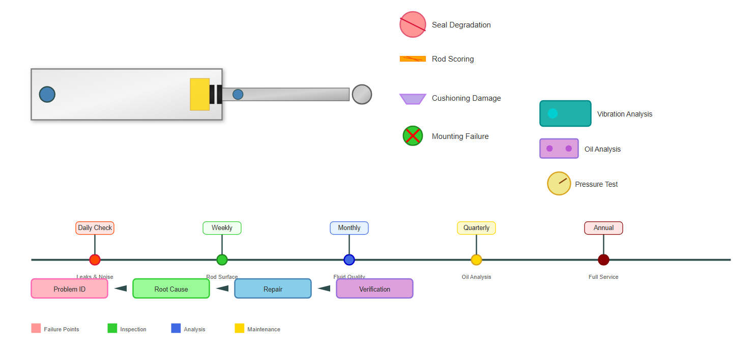
Check for leaks, abnormal noise, and proper operation
Examine rod surface for damage, check mounting hardware tightness
Measure fluid cleanliness, check cushioning performance
Perform oil analysis, inspect for corrosion, check alignment
Complete disassembly, seal replacement, component inspection
The importance of fluid cleanliness cannot be overstated in maintaining hydraulic cylinder longevity. Contamination particles accelerate wear of seals, scoring of precision surfaces, and degradation of hydraulic cylinder parts. Appropriate filtration systems, combined with proper fluid handling procedures, significantly extend component life and reduce maintenance requirements.