
Hydraulic control valves represent the cornerstone of modern fluid power technology, serving as the critical components that regulate and direct the flow of hydraulic fluid within complex industrial systems. These sophisticated devices function as the "traffic controllers" of hydraulic circuits, determining when, where, and how much pressurized fluid travels through various pathways to accomplish specific mechanical tasks.
The fundamental principle behind every hydraulic valve lies in its ability to manipulate fluid dynamics through precisely engineered internal passages and mechanisms.
In today's industrial landscape, hydraulic valves enable countless applications ranging from massive construction equipment to precision manufacturing systems. The evolution of hydraulic valve technology has paralleled the advancement of industrial automation, with modern designs incorporating sophisticated materials, precise manufacturing tolerances, and increasingly intelligent control systems.
Understanding the various types and functions of these valves is essential for engineers, technicians, and anyone involved in the design, maintenance, or operation of hydraulic systems.
The basic classification of hydraulic control valves falls into three primary categories based on their function: directional control valves that determine flow paths, pressure control valves that regulate system pressure, and flow control valves that manage volumetric flow rates. Each category encompasses numerous specialized designs tailored to specific applications and performance requirements.
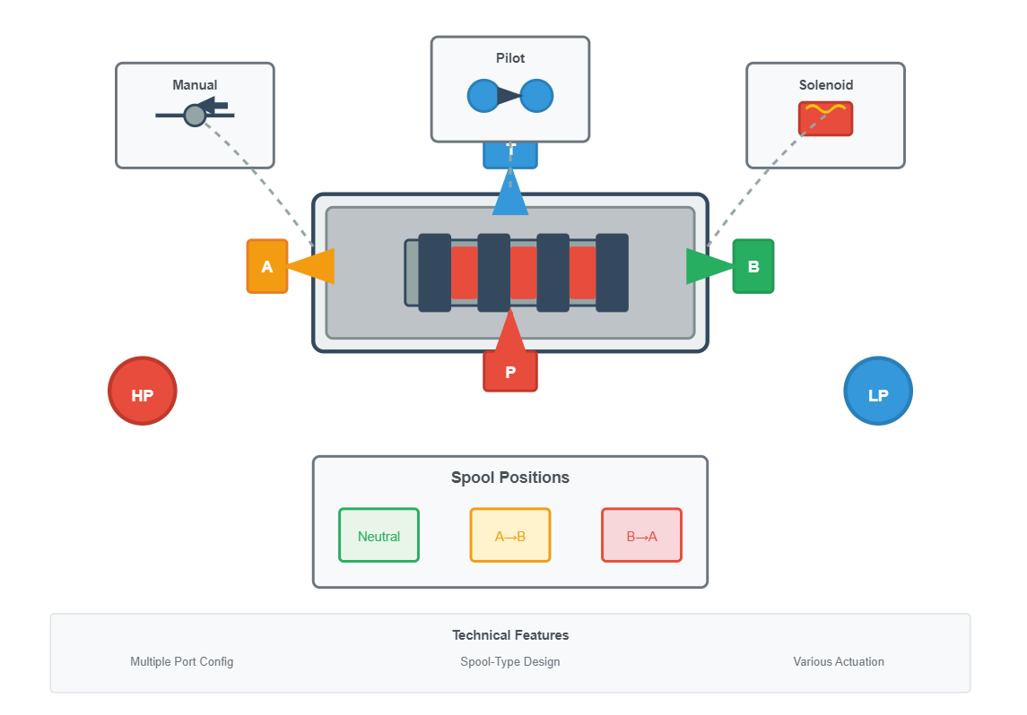
Control the start, stop, and direction of fluid flow, determining which actuator receives pressurized fluid and establishing return paths.
Spool-type designs
Multiple port configurations
Various actuation methods
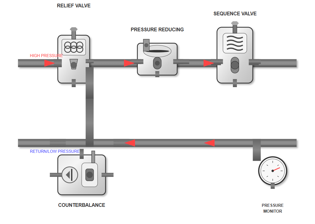
Maintain safe operation by regulating system pressure within predetermined limits, protecting components from damage.
Relief valves for safety
Pressure reducing capabilities
Sequence and counterbalance options
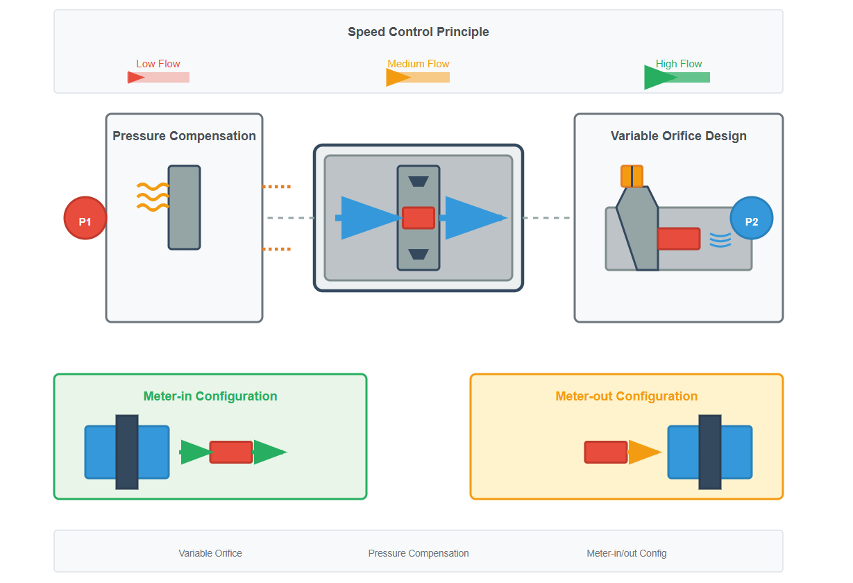
Regulate the speed of hydraulic actuators by controlling fluid volume, enabling precise speed control independent of load.
Variable orifice designs
Pressure compensation
Meter-in/out configurations
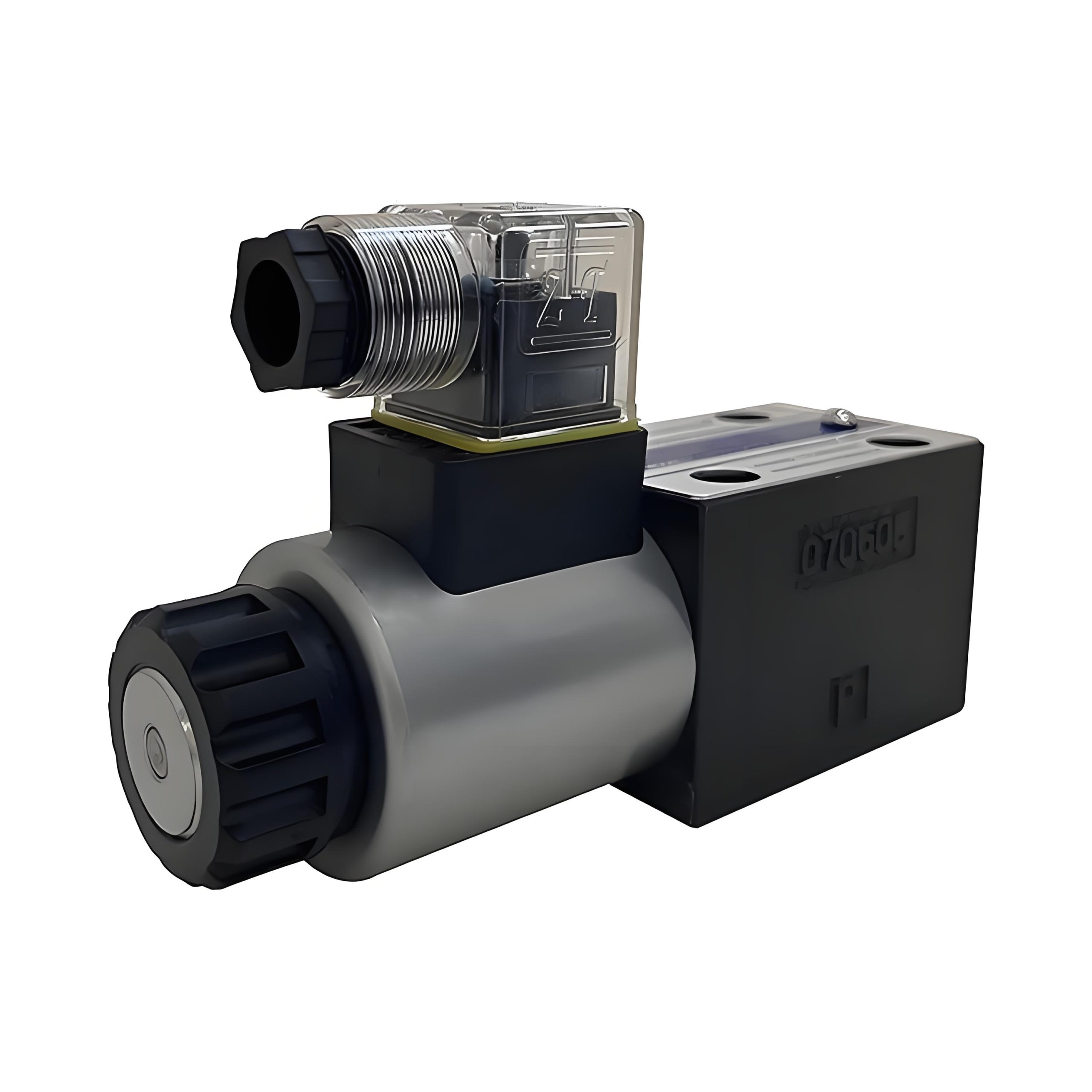
Directional control valves serve as the fundamental switching elements in hydraulic circuits, controlling the start, stop, and direction of fluid flow. These valves determine which actuator receives pressurized fluid and establish the return path for exhaust flow back to the reservoir.
The most common configuration is the spool-type directional valve, where a precisely machined spool slides within a bore to open and close various flow passages. The hydraulic valve design in directional control applications must balance factors such as flow capacity, pressure drop, internal leakage, and response time.
The classification of directional valves typically follows a standardized nomenclature indicating the number of ports and positions. For instance, a 4/3 directional valve features four ports and three distinct positions.
Ports generally include: pressure (P), tank return (T), and two work ports (A and B) that connect to the actuator.
Actuation methods for directional valves vary widely depending on application requirements. Manual operation through levers or push buttons suits simple applications, while solenoid actuation enables electrical control integration.
Levers, push buttons, or hand wheels for direct operator control in simple systems.
Electrical actuation enabling integration with PLCs and electronic control systems.
Uses system pressure to actuate larger valves where direct solenoid force is insufficient.
Air pressure actuation suitable for hazardous environments where electricity is restricted.
The hydraulic solenoid valve represents a crucial advancement in automation, allowing programmable logic controllers (PLCs) and other electronic systems to interface directly with hydraulic circuits. Hydraulic pilot operation provides another actuation method, particularly useful in high-flow applications where the forces required to shift large spools exceed the capability of direct solenoid actuation.
The performance characteristics of directional control valves significantly impact overall system efficiency and responsiveness. Flow capacity, typically expressed in gallons per minute or liters per minute, determines the maximum flow rate the valve can handle without excessive pressure drop. The pressure drop across a hydraulic valve directly affects system efficiency and heat generation, making proper sizing critical for optimal performance. Response time, particularly in high-speed applications, depends on factors including spool mass, spring forces, and actuation method.
Safety valves that open when system pressure exceeds a preset threshold, protecting components from damage.
Maintain constant reduced pressure in branch circuits regardless of main system pressure variations.
Ensure operations occur in predetermined order by preventing flow to secondary circuits until primary pressure is reached.
Provide controlled lowering of vertical loads by maintaining back pressure to prevent uncontrolled descent.
Pressure control valves maintain safe and efficient operation by regulating system pressure within predetermined limits. These essential components protect hydraulic systems from damage due to excessive pressure while ensuring adequate force generation for intended applications.
The hydraulic relief valve stands as the most fundamental pressure control device, acting as a safety valve that opens when system pressure exceeds a preset threshold. This protective function prevents catastrophic failures that could result from pressure spikes caused by sudden load changes or thermal expansion.
The operating principle of pressure relief valves involves a balance between hydraulic pressure forces and spring force. When system pressure acting on the valve poppet or spool exceeds the spring preload, the valve opens to divert excess flow to the tank.
Direct-acting: Respond quickly to pressure changes but may exhibit instability at high flow rates.
Pilot-operated: Use a small pilot section to control a larger main stage, providing stable operation across a wide flow range.
The selection and adjustment of pressure control valves require careful consideration of system dynamics and operating requirements. Setting relief valve pressure typically involves establishing a margin above normal operating pressure while remaining below component pressure ratings.
"The dynamic characteristics of hydraulic relief valves significantly influence system stability and performance. Proper selection of valve parameters, including spring stiffness, damping coefficient, and effective flow area, is crucial for preventing pressure oscillations and ensuring reliable operation across varying load conditions"
— Zhang et al., 2023, International Journal of Fluid Power
The differential between cracking pressure (when the valve begins to open) and full-flow pressure affects system efficiency and heat generation. Proper sizing ensures adequate flow capacity without excessive pressure override, which would waste energy and generate heat.
Flow control valves regulate the speed of hydraulic actuators by controlling the volume of fluid flowing through the circuit. These valves enable precise speed control independent of load variations, making them essential for applications requiring consistent motion profiles.
The basic flow control valve consists of a variable orifice that creates a restriction in the flow path, with the flow rate determined by the orifice size and pressure differential across it. However, simple orifice-type flow controls are load-dependent, as changes in load pressure affect the pressure drop and consequently the flow rate.
Pressure-compensated flow control valves address the load-dependency limitation by maintaining a constant pressure drop across the metering orifice regardless of inlet or outlet pressure variations.
This compensation typically involves a pressure-reducing compensator spool that automatically adjusts to maintain a fixed differential pressure. The result is consistent flow rate and actuator speed despite load changes, improving motion control precision in applications such as machine tools and material handling equipment.
Places the flow control valve between the pump and actuator, controlling the rate at which fluid enters the actuator.
Best for: Resistive loads
Consideration: May allow uncontrolled motion with overrunning loads
Positions the valve between the actuator and tank, creating back pressure that prevents cavitation.
Best for: Overrunning loads
Advantage: Provides better control of deceleration and prevents cavitation
Diverts excess flow to tank, offering energy-efficient speed control for fixed-displacement pump systems.
Best for: Fixed-displacement pump systems
Advantage: Energy efficient for certain applications
Modern flow control technology increasingly incorporates electronic feedback and control capabilities. The hydraulic flow meter provides real-time flow measurement that enables closed-loop control systems to maintain precise flow rates despite disturbances.
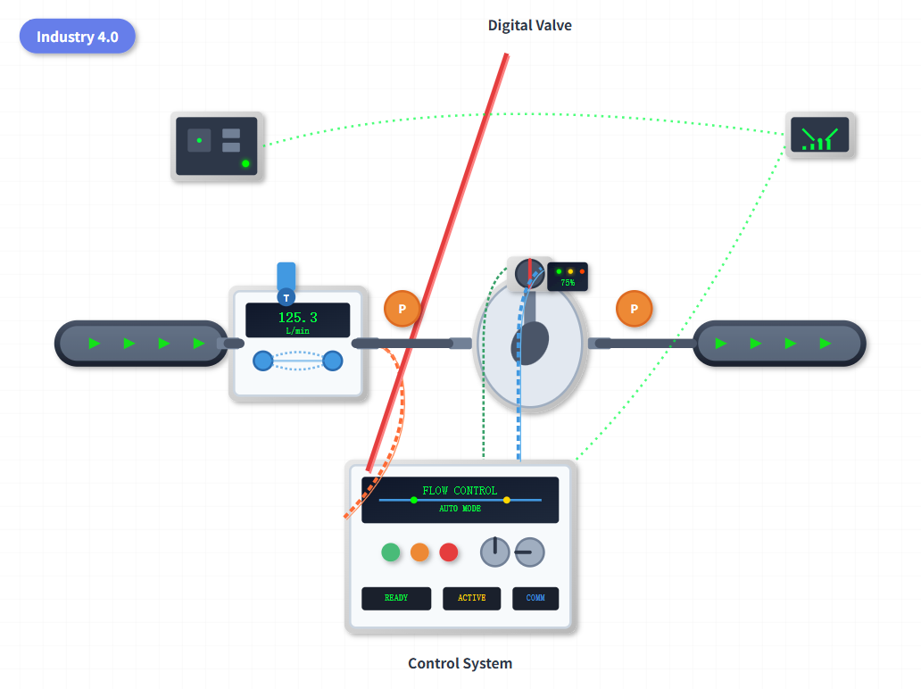
Incorporate integrated electronics offering programmable flow profiles, remote adjustment capabilities, and diagnostic functions. These advanced features support Industry 4.0 initiatives.
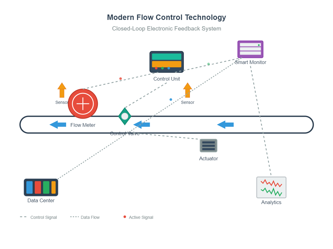
Enable predictive maintenance and process optimization through continuous monitoring and data analysis, integrating seamlessly with factory automation systems.
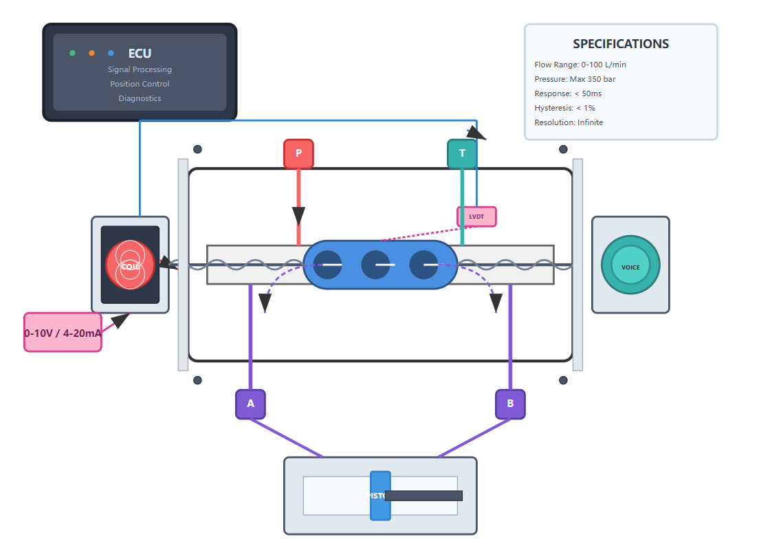
Proportional control valves represent a significant advancement in hydraulic valve technology, bridging the gap between simple on-off control and complex servo systems. These valves provide variable control of flow, pressure, or direction in proportion to an electrical input signal, enabling smooth and precise control of hydraulic actuators.
Unlike conventional solenoid valves that operate in discrete positions, proportional valves can assume any position within their range, offering infinite control resolution. This capability makes them ideal for applications requiring variable speed control, force control, or position control.
The heart of a proportional valve lies in its electro-mechanical actuator, typically a proportional solenoid or voice coil motor. These actuators convert electrical current into proportional mechanical force or displacement, which positions the valve spool or poppet.
Advanced proportional valves incorporate position feedback sensors that close the loop around spool position, improving accuracy and reducing hysteresis. The hydraulic control valve in proportional configurations often includes on-board electronics that handle signal conditioning, spool position control, and diagnostic functions.
The relationship between input signal and valve output follows a predetermined characteristic curve, usually linear within the operating range.
Smooth control of implements, improving operator comfort and productivity while reducing mechanical stress.
Program complex motion profiles and adjust parameters on-the-fly for precision processes.
Precise speed and position control for conveyors, lifts, and automated storage systems.
High-precision control for flight surfaces and landing gear systems.
System integration considerations for proportional valves encompass both hydraulic and electronic aspects. Hydraulic factors include ensuring adequate filtration to protect tight tolerances, managing heat generation from throttling losses, and providing stable supply pressure.
The trend toward distributed intelligence places more functionality at the valve level, including motion profile generation, fault detection, and communication capabilities. Modern proportional valve controllers offer various input options including analog voltage, current loops, and digital communication protocols.
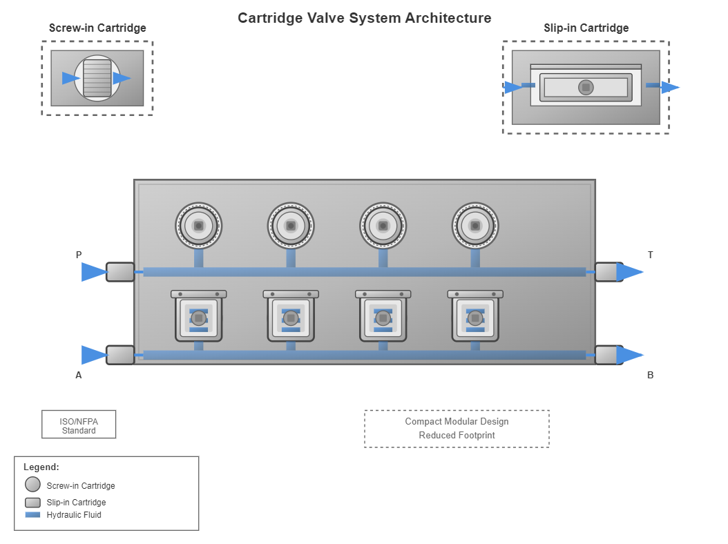
Cartridge valves, also known as slip-in valves, offer a modular approach to hydraulic circuit design that provides significant advantages in terms of flexibility, compactness, and maintenance efficiency. These valves consist of a valve element that fits into a standard cavity machined into a manifold block, with all external connections made through the manifold.
Handle auxiliary functions such as pressure relief, flow control, and check valve functions. These compact valves thread directly into manifold ports and typically handle flows up to 100 gallons per minute.
Designed for primary flow control, these can manage much higher flow rates, sometimes exceeding 1000 gallons per minute. They require a manifold with precisely machined cavities and are secured with a cover plate.
Significantly reduced footprint compared to conventional valve systems
Fewer connections eliminate potential leak points
Easy to configure and modify hydraulic circuits
Individual cartridges can be replaced without system disassembly
Reduced pressure losses through optimized internal flow paths
ISO and NFPA specifications ensure interchangeability
The modular nature of cartridge valve systems allows designers to create complex hydraulic circuits within compact manifold blocks, optimizing space utilization in mobile and industrial equipment. This design eliminates external piping between valve functions, reducing potential leak points and improving system reliability.
The standardized cavity designs, following ISO and NFPA specifications, ensure interchangeability between manufacturers and simplify inventory management.
Stack valves, also known as sandwich valves or modular valves, provide another approach to creating compact hydraulic circuits. These valves mount between a directional control valve and its subplate, adding auxiliary functions without additional piping.
Common stack valve functions include flow control, pressure reduction, and check valve operations. The standardized mounting patterns, based on NFPA and ISO specifications, ensure compatibility between different manufacturers' products.
This modularity allows system designers to add or modify functions easily, adapting to changing application requirements without extensive system redesign.
The integration of cartridge and stack valves with modern hydraulic valves creates highly efficient and reliable systems. Electronic controls increasingly complement these modular valve systems, with proportional cartridge valves offering variable control within compact manifolds.
Smart manifolds incorporate sensors and electronics directly into the manifold block, creating intelligent hydraulic systems that monitor their own performance and communicate with higher-level control systems. The combination of mechanical modularity and electronic intelligence represents the future direction of hydraulic control technology.