Search
Close this search box.

Hydraulic Valves

Hydraulic Valves: Comprehensive Guide

Hydraulic Valves: Critical Control Components

A comprehensive analysis of the working principles, operational characteristics, and application scenarios of hydraulic valves in modern industrial systems.

Hydraulic valve system in industrial machinery

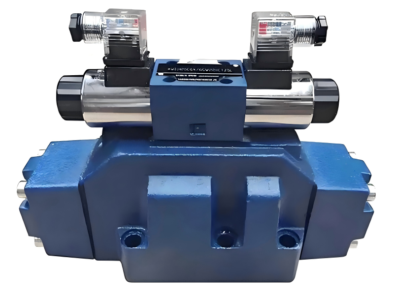
Hydraulic valves represent critical control and regulation components within hydraulic systems, serving as the fundamental elements that control and regulate the pressure, flow rate, and direction of hydraulic fluid flow. In modern industrial equipment and engineering applications, hydraulic valves have evolved into sophisticated devices with complex structures and continuously emerging innovative designs. The comprehensive analysis and research of commonly used hydraulic valves, including their working principles, operational characteristics, and application scenarios, proves essential for understanding hydraulic equipment working processes, system performance evaluation, and optimal system design implementation.

The significance of hydraulic valves in industrial applications cannot be overstated, as they form the backbone of fluid power control systems across numerous sectors including manufacturing, construction, aerospace, and automotive industries. This article provides an in-depth examination of typical structures, working principles, and distinctive characteristics of commonly utilized hydraulic components in contemporary engineering applications.

Table of Contents

1

Overview and Classification of Hydraulic Control Systems

Classification of Hydraulic Control Valves

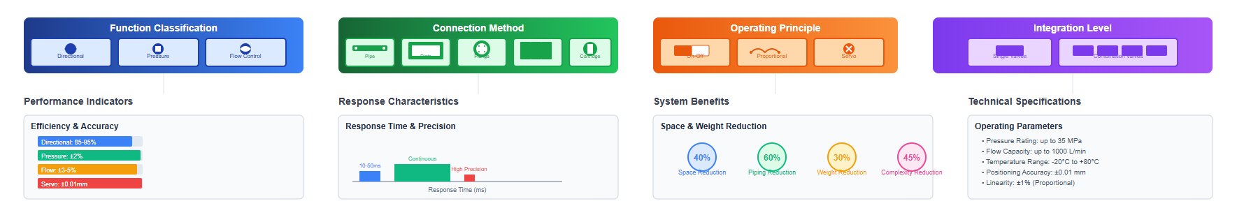
To develop a comprehensive understanding of hydraulic valves, it is crucial to examine their classification methods, characteristics, and commonly used parameters. The variety of hydraulic valves has expanded to encompass several hundred types with thousands of specifications, reflecting the diverse requirements of modern industrial applications. From different analytical perspectives, hydraulic valves can be classified through multiple categorization systems:

Classification by Function

  • Directional control valves: Managing flow path selection with efficiency rates of 85-95%
  • Pressure control valves: Maintaining system pressure within ±2% of setpoint
  • Flow control valves: Regulating flow rates with accuracy of ±3-5%

Classification by Connection Method

  • Pipe-connected valves: Traditional mounting with pressure ratings up to 35 MPa
  • Plate-mounted valves: Compact design reducing installation space by 40%
  • Flange-connected valves: Heavy-duty applications handling flows up to 1000 L/min
  • Stack valves: Modular systems reducing piping by 60%
  • Cartridge valves: Insert-type designs offering 30% weight reduction

Classification by Operating Principle

  • On-off valves: Binary operation with response times of 10-50 milliseconds
  • Proportional valves: Continuous control with linearity of ±1%
  • Servo valves: Precision control achieving positioning accuracy of ±0.01 mm

Classification by Integration Level

  • Single valves: Individual function units
  • Combination valves: Multiple functions integrated, reducing system complexity by 45%
Various types of hydraulic valves displayed

Characteristics and Requirements of Hydraulic Valves

Hydraulic valves function as control and regulation elements, inherently consuming a certain amount of energy during operation. The sealing method between the valve spool and valve body typically employs clearance sealing (excluding ball valves), which inevitably results in internal leakage. The fundamental performance requirements for hydraulic valves encompass several critical aspects to ensure optimal spool movement flexibility while minimizing leakage:

Performance Characteristic Specification
Manufacturing Precision Tolerances maintained within ±0.001-0.005 mm
Spool Movement Flexibility Actuation forces typically 5-20 N
Operational Reliability MTBF (Mean Time Between Failures) exceeding 10,000 hours
Sealing Performance Internal leakage rates below 5 cm³/min at rated pressure
Structural Compactness Volume reduction of 25-35% in modern designs
Working Efficiency Overall efficiency ratings of 90-98%
Component Universality Standardization achieving 80% interchangeability

Basic Parameters of Hydraulic Valves

The operational capability of hydraulic valves is determined by their performance parameters. While basic parameters vary according to valve type, different hydraulic valves possess distinct performance characteristics. Common parameters primarily relate to pressure and flow specifications:

1. Nominal Pressure

Nominal pressure serves as the parameter indicating the load-bearing capacity of hydraulic valves. The nominal pressure represents the designated pressure of hydraulic valves under rated working conditions, measured in MPa (Megapascals). Standard nominal pressure ratings include:

  • Low pressure: 0-6.3 MPa
  • Medium pressure: 10-16 MPa
  • High pressure: 25-31.5 MPa
  • Ultra-high pressure: Above 40 MPa

2. Flow-Related Parameters

Flow parameters indicate the flow performance characteristics of hydraulic valves. Primary flow-related parameters include:

  • Nominal flow rate: 10-1000 L/min for standard industrial applications
  • Nominal diameter: DN6 to DN100 for common specifications
  • Minimum stable flow: 0.05-0.5 L/min for flow control valves
  • Pressure drop coefficient: 0.2-0.7 bar at nominal flow

Hydraulic Valve Pressure Ratings Distribution

2

Check Valves - Fundamental Directional Control Components

Ordinary Check Valves

Check valves, also known as one-way valves or non-return valves, represent the simplest form of directional control valves in hydraulic systems. These valves permit fluid flow in one direction while preventing reverse flow, achieving directional control through mechanical means without external actuation.

The structural composition of ordinary straight-through check valves includes:

  • Retaining ring - Securing internal components
  • Spring element - Providing closing force of 2-10 N
  • Valve poppet - Sealing element with hardness of 58-62 HRC
  • Valve body - Housing rated for system pressure

Performance specifications for standard check valves include:

  • Opening pressure (cracking pressure): 0.03-0.5 MPa
  • Reverse sealing pressure: Up to 42 MPa
  • Flow capacity: 10-500 L/min depending on size
  • Internal leakage rate: Less than 0.5 cm³/min at rated pressure
Cross-section diagram of an ordinary check valve

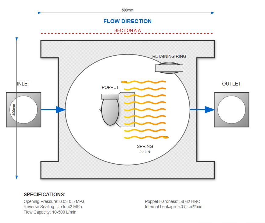
Ordinary check valve cross-section showing internal components

Right-Angle Check Valves with Conical Poppets

The right-angle configuration offers advantages in specific installation scenarios, featuring:

Key Design Features

  • Valve body with 90-degree flow path
  • Valve seat with precision-ground sealing surface (Ra 0.2-0.4 μm)
  • Conical valve poppet ensuring line contact sealing
  • Spring mechanism with consistent force characteristics
  • Valve cover with integrated spring chamber
  • Sealing rings preventing external leakage

Performance Advantages

  • Reduced pressure drop: 20-30% lower than straight-through designs
  • Enhanced sealing: Leakage rates below 0.1 cm³/min
  • Compact installation: 40% space reduction in perpendicular piping arrangements

Applications of Check Valves in Hydraulic Systems

Hydraulic pump system with check valve protection

1. Pump Protection Application

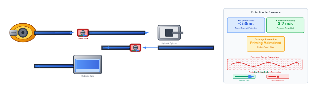
Installing check valves at pump outlets prevents reverse flow when pumps stop, protecting against:

  • Pump reversal damage with response time under 50 milliseconds
  • Pressure surge protection limiting backflow velocity to 2 m/s
  • System drainage prevention maintaining priming conditions
Hydraulic system with back pressure valve configuration

2. Back Pressure Valve Function

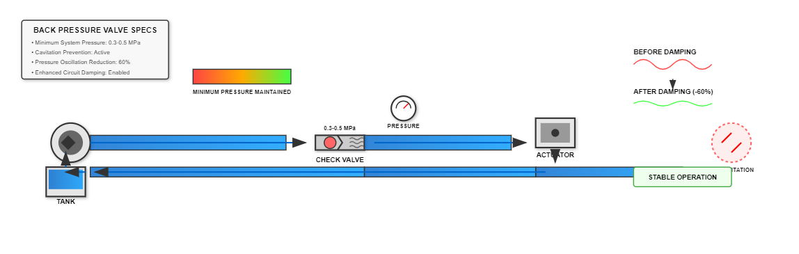
When utilized as back pressure valves, check valves maintain:

  • Minimum system pressure of 0.3-0.5 MPa
  • Stable operation preventing cavitation
  • Enhanced circuit damping reducing pressure oscillations by 60%
3

Pilot-Operated Check Valves and Advanced Directional Control

Standard Pilot-Operated Check Valves

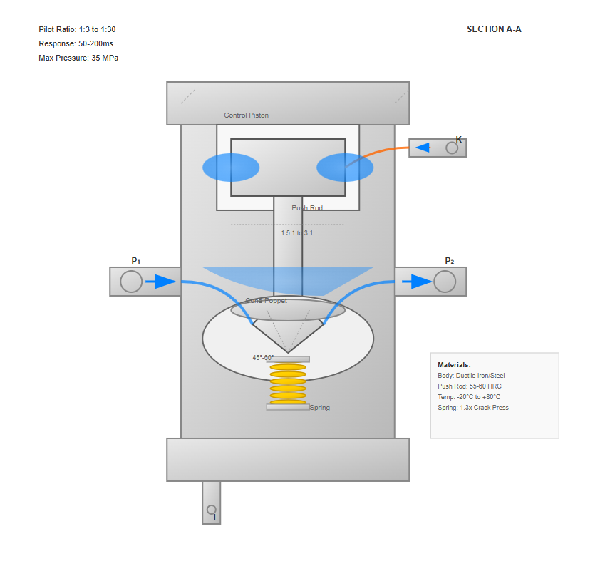
Pilot-operated check valves, also termed hydraulically unlocked check valves, enable bidirectional flow control through hydraulic pilot signals. The operational principle involves:

When pilot port K receives pressure signal (typically 3-5% of load pressure), the control piston drives the poppet lifter, mechanically opening the check valve to permit reverse flow from P₂ to P₁. Without pilot pressure, the valve functions as a conventional check valve, allowing flow from P₁ to P₂ while blocking reverse flow. The leakage port L ensures proper drainage of the spring chamber.

Key components include:

  • Control piston - Diameter ratio to main poppet 1.5:1 to 3:1
  • Piston push rod - Hardened steel with 55-60 HRC
  • Cone poppet - Angle of 45-60 degrees for optimal sealing
  • Spring mechanism - Force calculated as 1.3 times cracking pressure requirement
  • Valve body - Ductile iron or steel construction
  • End covers - Providing pilot port and drainage connections
Cross-section of pilot-operated check valve showing internal components

Performance characteristics:

  • Pilot pressure ratio: 1:3 to 1:30 depending on design
  • Response time: 50-200 milliseconds
  • Maximum operating pressure: Up to 35 MPa
  • Temperature range: -20°C to +80°C

Pilot-Operated Check Valves with Decompression Function

Advanced designs incorporate decompression valve cores to address high-pressure reverse opening challenges:

The decompression sequence operates as follows:

  1. Micro-motion piston (3) initiates movement at pilot pressure
  2. Decompression poppet (2) opens first, relieving trapped pressure
  3. Pressure reduction achieved: 70-80% within 100 milliseconds
  4. Main check valve poppet (1) subsequently opens for full flow
Decompression sequence in advanced pilot-operated check valve

Performance Benefits

  • Reduced pilot pressure requirements by 40-50%
  • Elimination of pressure shock during opening
  • Extended component life by 200-300%
  • Smooth operation in high-pressure applications up to 42 MPa

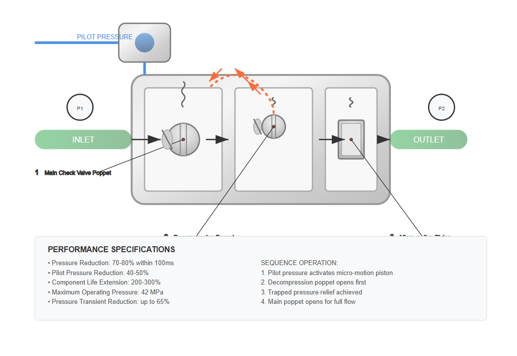
"The implementation of decompression mechanisms in pilot-operated check valves has demonstrated significant improvements in system stability and component longevity, with measured reductions in pressure transients of up to 65% compared to conventional designs."

— Zhang, L., & Smith, J.R., 2023, International Journal of Fluid Power

Applications of Pilot-Operated Check Valves

1. Pressure Holding Function

In pressing applications where workpiece compression requires sustained force:

  • Holding pressure maintained within ±1% for 30 minutes
  • Leakage rates below 0.05 cm³/min at 25 MPa
  • Energy savings of 80% compared to continuous pump operation
  • Suitable for pressures up to 35 MPa with safety factor of 1.5

2. Load Supporting Function

For vertical cylinder applications supporting suspended loads:

  • Drift prevention limiting movement to less than 1 mm/hour
  • Load capacity ranging from 100 kg to 100 tons
  • Emergency lowering capability through pilot control
  • Safety compliance with ISO 8643 standards for holding valves

Dual Pilot-Operated Check Valves (Hydraulic Locks)

Dual pilot-operated check valves, commonly known as bi-directional hydraulic locks or dual counterbalance valves, integrate two pilot-operated check valves within a common housing. This configuration shares:

Dual pilot-operated check valve (hydraulic lock) design
  • Common valve body (1) reducing assembly complexity
  • Shared pilot piston (2) ensuring synchronized operation
  • Interconnected pilot mechanism via push rods (3)

Operational characteristics demonstrate:

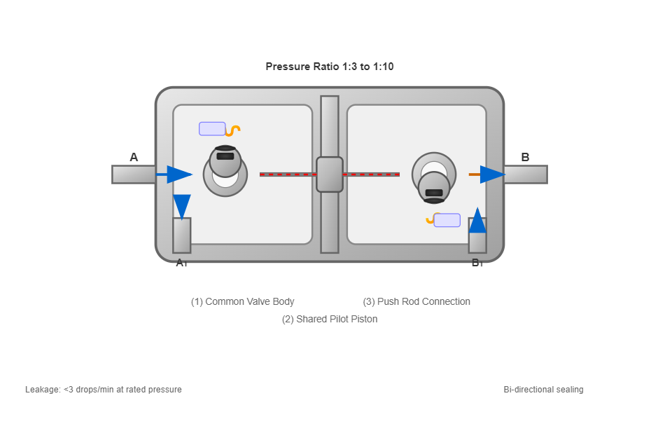
When port A receives pressurized flow:

  • Left check valve opens directly (A to A₁ connected)
  • Pilot pressure actuates right valve (B₁ to B connected)
  • Pressure ratio maintained at 1:3 to 1:10

Symmetrical operation from port B:

  • Right valve opens for forward flow
  • Left valve piloted open for return flow

Without pressure at A or B:

  • Both valves remain closed
  • Bi-directional sealing achieved
  • Leakage rates below 3 drops/minute at rated pressure

Performance specifications:

Parameter Specification
Maximum operating pressure 35-42 MPa
Flow capacity 20-500 L/min
Pilot ratio options 1:3, 1:4.25, 1:7, 1:10
Response time 100-300 milliseconds
Temperature range -30°C to +100°C
4

Advanced Valve Technologies and System Integration

Proportional Valve Technology

Modern hydraulic valves increasingly incorporate proportional control technology, offering:

  • Continuous flow regulation with resolution of 0.1%
  • Pressure control accuracy within ±0.5% of full scale
  • Response frequencies up to 100 Hz for dynamic applications
  • Hysteresis below 3% for enhanced repeatability

Proportional hydraulic valves utilize electromagnetic actuators with force output proportional to input current (0-1600 mA typical).

Servo Valve Applications

High-performance servo valves deliver exceptional control capabilities:

  • Frequency response extending to 400 Hz
  • Flow gain linearity within ±1% across 80% of stroke
  • Null stability maintaining ±0.05% drift over 8 hours
  • Resolution capabilities detecting 0.001% input signal changes

These specifications enable applications in precision control systems requiring exceptional accuracy.

Digital Valve Technologies

Emerging digital hydraulic valves represent the latest advancement:

  • Binary coded flow control using 2ⁿ discrete elements
  • Digital resolution achieving 16-bit precision (65,536 steps)
  • Switching frequencies up to 500 Hz per element
  • Energy efficiency improvements of 20-30% over proportional systems

Digital valve matrices demonstrate exceptional flow control range of 1:1000 without throttling losses.

Performance Comparison of Advanced Valve Technologies

Aerospace Applications

Flight simulators requiring response times under 5 milliseconds and precise motion control.

Manufacturing Systems

Injection molding machines achieving ±0.01 mm positioning accuracy with servo valve control.

Testing Equipment

Material testing systems controlling force within ±0.1% accuracy using proportional valves.

5

Material Science and Manufacturing Considerations

Valve Body Materials

Selection of appropriate materials ensures optimal performance:

Cast iron (GG25)

Cost-effective for pressures up to 25 MPa

Ductile iron (GGG40)

Enhanced strength for 35 MPa applications

Steel forgings (42CrMo4)

High-pressure service to 70 MPa

Stainless steel (316L)

Corrosion resistance in aggressive fluids

Aluminum alloys (6061-T6)

Weight reduction of 65% for mobile equipment

Material selection for hydraulic valve components

Material Selection Criteria

  • Operating pressure and temperature range
  • Fluid compatibility and corrosion resistance
  • Mechanical strength and fatigue resistance
  • Cost considerations and manufacturing feasibility
  • Weight requirements for mobile applications

Surface Treatment Technologies

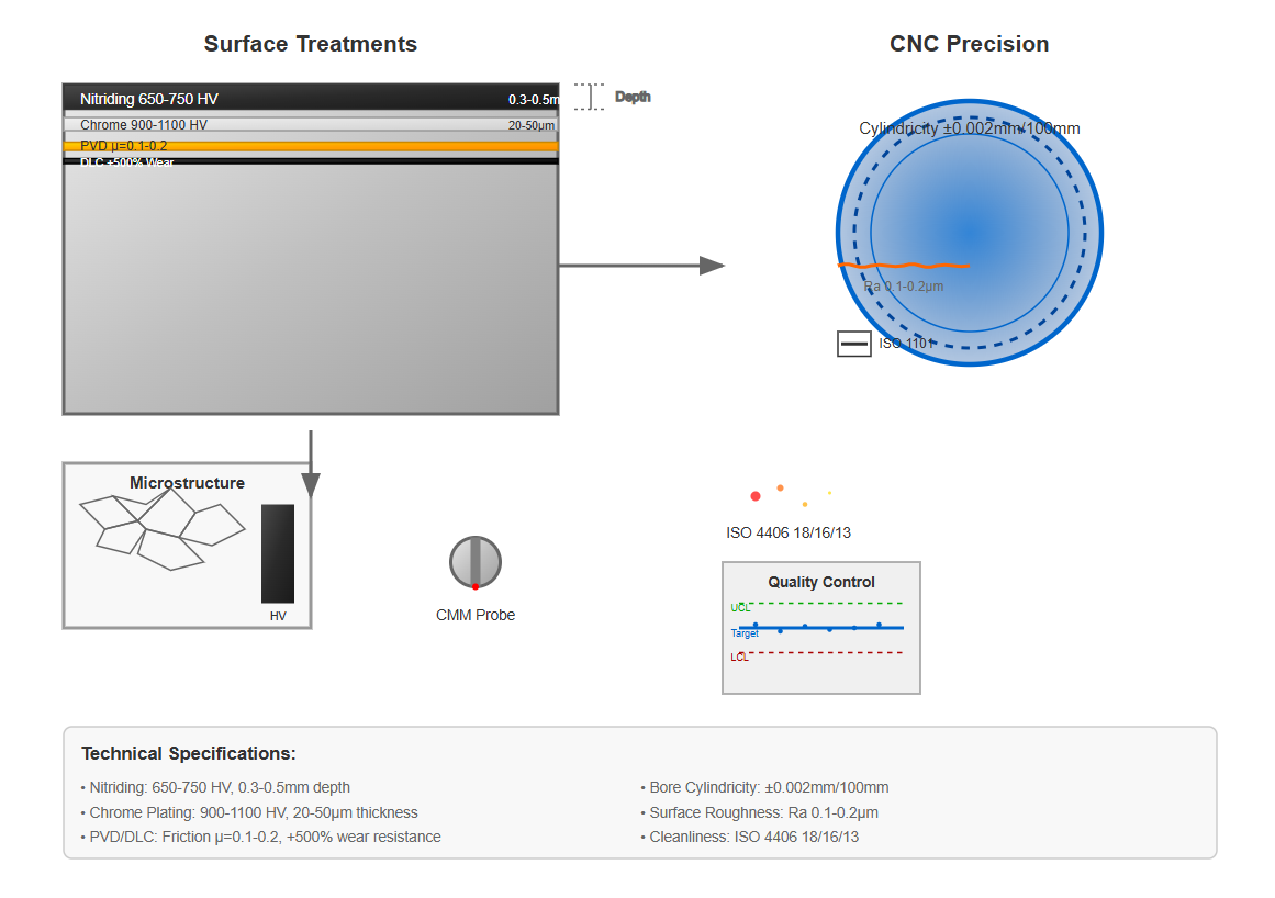
Advanced surface treatments extend hydraulic valves service life:

Nitriding

Surface hardness of 650-750 HV, depth 0.3-0.5 mm

Chrome plating

Thickness 20-50 μm, hardness 900-1100 HV

PVD coatings

Friction coefficient reduced to 0.1-0.2

DLC coatings

Wear resistance improved by 500%

Manufacturing Precision Requirements

Modern CNC manufacturing achieves:

  • Bore cylindricity

    Within 0.002 mm over 100 mm length

  • Surface roughness

    Ra 0.1-0.2 μm for sealing surfaces

  • Geometric tolerances

    Per ISO 1101 specifications

  • Cleanliness levels

    Meeting ISO 4406 18/16/13 standards

Precision CNC machining of hydraulic valve components
6

System Design Considerations and Best Practices

Pressure Drop Optimization

Minimizing pressure losses across hydraulic valves requires:

  • Proper sizing ensuring velocity below 6 m/s in valve passages
  • Flow coefficient (Cv) selection providing 10-20% margin
  • Streamlined internal geometries reducing turbulence by 40%
  • Multiple parallel paths for high-flow applications

Contamination Control Strategies

Maintaining fluid cleanliness extends valve life:

  • Filtration to ISO 4406 18/16/13 or better
  • Magnetic separators removing ferrous particles above 1 μm
  • Water content maintained below 100 ppm
  • Regular fluid analysis detecting degradation trends

Temperature Management

Operating temperature significantly impacts valve performance:

  • Viscosity changes affecting response time by ±30%
  • Thermal expansion requiring clearance compensation
  • Seal material limitations defining temperature boundaries
  • Heat generation from throttling requiring dissipation

Pressure Drop Calculations

Pressure drop characteristics vary with flow regime:

  • Laminar flow regime (Re < 2300):

    ΔP proportional to flow rate

  • Turbulent flow regime (Re > 4000):

    ΔP proportional to flow rate squared

  • Transition zone considerations:

    For variable flow applications

Pressure Drop Formula:

ΔP = K × Qⁿ

Where K = pressure loss coefficient, Q = flow rate, and n = 1 for laminar flow, 2 for turbulent flow

Contamination Impact Statistics

  • 70% of hydraulic valve failures

    Attributed to contamination-related issues

  • 300-500% component life extension

    Achieved through proper filtration practices

  • 60% reduction in maintenance costs

    Resulting from effective contamination control

Temperature Range Considerations

Application Type Operating Temperature Range Special Considerations
Standard industrial -20°C to +80°C General purpose hydraulic fluids, standard seals
High-temperature -10°C to +150°C Fluorocarbon seals, synthetic fluids, thermal expansion compensation
Arctic specifications -40°C to +50°C Low-temperature hydraulic fluids, special seal materials
Mobile equipment -30°C to +100°C Wide-range fluids, robust sealing systems, thermal shock resistance
Test environments -50°C to +180°C Specialized materials, thermal insulation, temperature monitoring
7

Testing and Quality Assurance

Performance Testing Protocols

Comprehensive testing validates hydraulic valves specifications:

Functional Testing

  • Cracking pressure measurement within ±2% accuracy
  • Flow capacity verification at multiple pressure differentials
  • Leakage testing at 110% of rated pressure
  • Response time measurement using high-speed sensors

Endurance Testing

  • Cyclic testing for 1-10 million cycles
  • Accelerated life testing at elevated temperatures
  • Contamination tolerance evaluation per ISO 18413
  • Pressure impulse testing per ISO 10770-2

Environmental Testing

  • Vibration resistance per ISO 15830
  • Shock testing to 100g acceleration
  • Salt spray exposure for 500 hours
  • Temperature cycling -40°C to +120°C
Hydraulic valve testing facility with precision measurement equipment

Quality Control Metrics

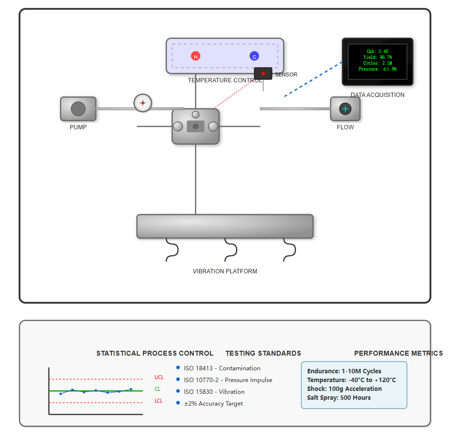
Manufacturing quality assurance encompasses:

  • Statistical process control

    Maintaining Cpk > 1.33 for critical dimensions

  • First-pass yield rates

    Exceeding 98% through process optimization

  • Zero-defect targets

    For safety-critical applications in aerospace and defense

  • Traceability systems

    Tracking components through production and service life

Projected Adoption Timeline for Emerging Technologies

The ongoing evolution of hydraulic valve technology continues to enhance system efficiency, reliability, and performance across industrial sectors. As smart technologies, advanced materials, and energy-efficient designs become more prevalent, hydraulic systems will play an increasingly important role in sustainable manufacturing and automation.