
Comprehensive technical overview of pressure control systems, operational principles, and advanced design features
Pressure control valves represent a fundamental category of hydraulic components that regulate and maintain system pressure within predetermined parameters. The hydraulic relief valve serves as the cornerstone of pressure management in modern hydraulic systems, providing critical protection against overpressure conditions while ensuring optimal operational efficiency. These sophisticated devices control pressure magnitudes throughout circuits, functioning as either primary control elements or safety mechanisms depending on system requirements.
In contemporary industrial applications, these valves operate on the principle of force balance between hydraulic pressure and mechanical spring force. When system pressure reaches the predetermined setpoint, typically ranging from 0.5 MPa to 63 MPa depending on design specifications, the hydraulic relief valve initiates controlled fluid discharge to maintain system stability. Statistical analysis indicates that properly configured installations reduce system failures by approximately 75% compared to unprotected circuits.
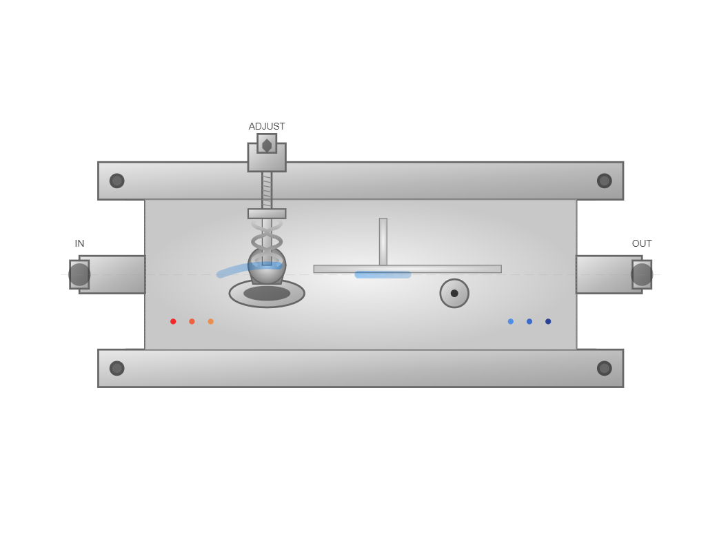
Cross-section of a modern hydraulic relief valve showing internal components and flow paths
Key Function: Protects hydraulic systems from overpressure conditions
The direct-acting hydraulic relief valve utilizes a straightforward mechanical design where hydraulic force directly opposes spring tension. In these configurations, when pressure acting on valve area A reaches the threshold value p₁, satisfying the equation:
p₁A = F₁ = kx₀
where k represents spring stiffness (typically 50-500 N/mm) and x₀ denotes precompression distance (usually 5-25 mm)
The valve begins to open. This direct-acting design exhibits rapid response characteristics, with opening times typically under 10 milliseconds.
Performance metrics for direct-acting systems demonstrate pressure regulation accuracy within ±2% of setpoint values under steady-state conditions. The hydraulic relief valve in this configuration maintains flow rates from 10 to 300 L/min, with pressure fluctuations limited to 0.5 MPa during normal operation. Advanced designs incorporating damping pistons reduce pressure oscillations by 60-80%, enhancing overall stability.
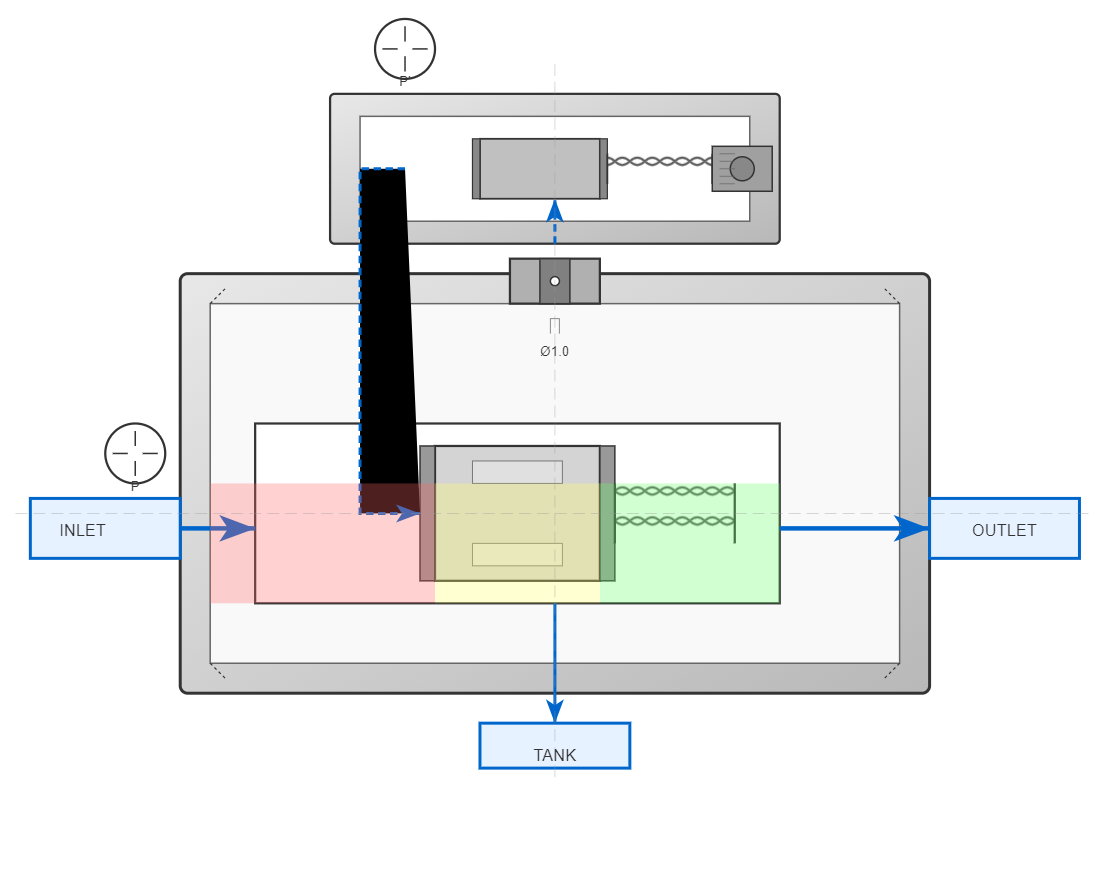
Pilot valve controls main valve operation for enhanced precision
0.8-1.2 mm diameter creates controlled pressure differential
Typically ranges from 0.3 to 2.0 MPa across main spool
Pilot-operated designs employ a two-stage architecture consisting of a pilot valve controlling main valve operation. This sophisticated hydraulic relief valve configuration enables precise pressure control across extensive flow ranges, typically from 50 to 2000 L/min. The pilot section maintains a pressure differential across the main spool through a calibrated orifice (diameter 0.8-1.2 mm), creating controlled pressure drop Δp = p - p'.
When system pressure exceeds the pilot valve setting, the pilot stage opens, establishing flow through the damping orifice. This creates a pressure differential acting on the main spool area, with typical differential pressures ranging from 0.3 to 2.0 MPa. The main stage subsequently opens when the pressure-induced force overcomes the light main spring force (typically 10-50 N), allowing full flow capacity.
Pilot-operated designs provide superior pressure control accuracy across a wider flow range compared to direct-acting valves, making them ideal for large hydraulic systems with varying flow demands.
The hydraulic relief valve exhibits distinct static characteristics defining operational boundaries. Opening pressure ratios for quality units exceed 90%, with closing pressure ratios surpassing 85%. These parameters ensure minimal pressure variation during flow transitions.
Opening Pressure Ratio
> 90%
Closing Pressure Ratio
> 85%
The pressure-flow characteristic of a properly designed valve shows less than 5% pressure increase from minimum to maximum rated flow, ensuring stable system operation across varying demand conditions.
Modern designs accommodate adjustment ranges spanning 1:7 ratios within a single spring configuration. For instance, a hydraulic relief valve equipped with appropriate spring selection enables pressure settings from 2 MPa to 14 MPa without component changes. Extended ranges up to 35 MPa utilize multiple spring options, providing comprehensive adaptability.
Dynamic performance determines system response to transient conditions. Pressure overshoot during sudden loading typically remains below 15% of setpoint pressure for well-designed systems. Transition time from fully closed to stable open position ranges from 20 to 100 milliseconds depending on valve size and design parameters.
"Modern pilot-operated hydraulic relief valve designs demonstrate superior dynamic stability compared to direct-acting models, with pressure oscillation amplitudes reduced by up to 70% under identical operating conditions. These improvements result from optimized flow force compensation and enhanced damping characteristics inherent in two-stage valve architectures"
Source: International Fluid Power Society, Technical Bulletin TB-2024-15, www.ifps.org
Pressure stability during steady-state operation represents a key performance metric. Premium designs maintain pressure variations within ±1% of setpoint under constant flow conditions. Temperature compensation features in advanced models reduce thermal drift to less than 0.02 MPa/°C, ensuring consistent performance across operating temperature ranges from -20°C to +80°C.
Contemporary hydraulic relief valve designs incorporate sophisticated flow force compensation mechanisms. The deflector plate configuration generates hydraulic forces opposing spring compression, effectively linearizing the pressure-flow characteristic. This technology enables a single valve to maintain stable operation across flow variations exceeding 20:1 ratios.
Computational fluid dynamics analysis reveals that optimized deflector geometry reduces required spring rates by 40-60%. Lower spring rates translate to expanded adjustment ranges and improved sensitivity. The incorporation of radial flow grooves in the deflector enhances flow capacity by 25-35% compared to conventional designs while maintaining equivalent pressure stability.
40-60%
Reduction in required spring rates
20:1
Flow variation ratio capability
25-35%
Flow capacity enhancement
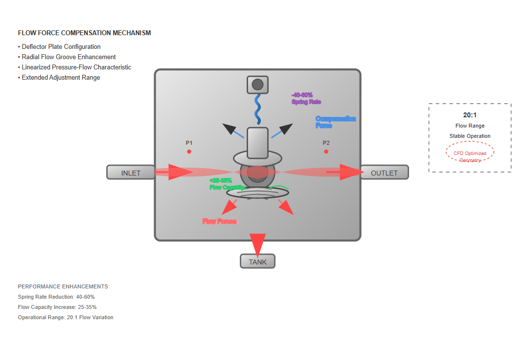
Advanced deflector plate designs create opposing hydraulic forces that linearize pressure-flow characteristics, improving stability across operating ranges.
Occurs through controlled clearances (typically 0.02-0.05 mm) between the damping piston and valve body, providing viscous damping proportional to spool velocity.
Results from strategically positioned orifices (0.5-1.5 mm diameter) connecting pressure chambers, creating pressure feedback loops that counteract oscillatory tendencies.
Advanced designs integrate multiple damping mechanisms to eliminate instability. Primary damping occurs through controlled clearances (typically 0.02-0.05 mm) between the damping piston and valve body. This configuration provides viscous damping proportional to spool velocity, with damping coefficients ranging from 50 to 200 Ns/m depending on valve size and oil viscosity.
Secondary damping in the hydraulic relief valve results from strategically positioned orifices connecting pressure chambers. These passages, typically 0.5-1.5 mm diameter, create pressure feedback loops that anticipate and counteract oscillatory tendencies. The valve achieves critical damping ratios between 0.7 and 1.0, ensuring rapid response without overshoot.
Damping ratios between 0.7 and 1.0 ensure rapid response without overshoot, maintaining system stability during transient conditions.
Precisely sized orifices (0.5-1.5 mm) create optimal pressure feedback loops that anticipate and counteract oscillatory tendencies in the system.
The hydraulic relief valve functions as a system pressure limiter in variable displacement pump circuits. Setting the valve at maximum safe system pressure (typically 10-15% above normal operating pressure) provides overpressure protection while allowing normal pump control functions.
In these applications, the valve remains closed during standard operation, opening only during fault conditions or load spikes exceeding pump displacement capability.
Industrial statistics indicate that hydraulic relief valve implementation as safety devices prevents approximately 90% of potential overpressure failures.
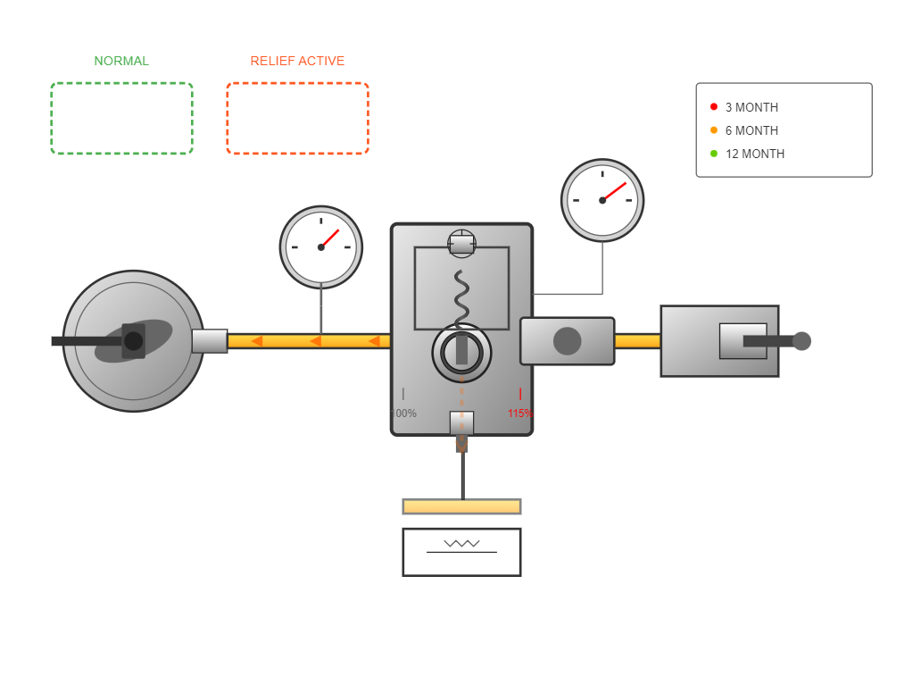
Safety applications require periodic testing to ensure proper functionality, with recommended intervals:
Valve utilization in unloading circuits enables energy-efficient pump operation during idle periods. Connection of the remote control port to tank through a solenoid valve creates an unloading function. When energized, the solenoid diverts pilot flow, causing the main hydraulic relief valve to open fully.
This configuration reduces pump pressure to approximately 0.2-0.45 MPa, minimizing power consumption by 85-95% during standby operation.
0.2-0.45 MPa during standby
85-95% during idle periods
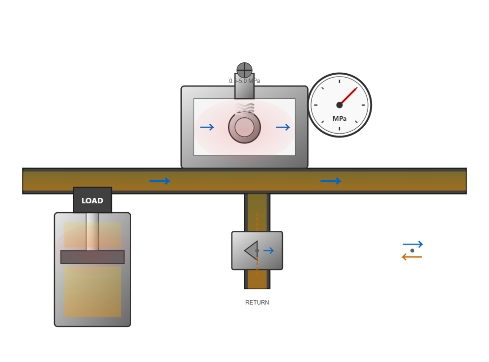
Implementation of the hydraulic relief valve as a back pressure device enhances motion control in vertical axis and high-inertia applications. Installing the valve in the return line creates controlled resistance, preventing load runaway and ensuring smooth deceleration.
Back pressure settings typically range from 0.5 to 5.0 MPa, depending on load characteristics and required damping levels.
The valve in back pressure service experiences reverse flow during certain operational phases. Specialized designs incorporate anti-cavitation features, including integrated check valves or modified seat geometries, preventing damage during flow reversal conditions. These enhanced hydraulic relief valve configurations maintain functionality across bidirectional flow conditions while preserving pressure control accuracy.
Comprehensive testing encompasses static and dynamic performance evaluation. Standard test protocols measure opening pressure accuracy within ±1% using calibrated pressure transducers with 0.1% accuracy ratings. The hydraulic relief valve undergoes flow testing at 25%, 50%, 75%, and 100% of rated capacity, documenting pressure rise characteristics at each point.
Endurance testing subjects the valve to accelerated lifecycle simulation. Typical test sequences include 1 million operational cycles at rated conditions, with performance measurements at 100,000 cycle intervals. Quality designs demonstrate less than 2% setpoint drift throughout testing, confirming long-term stability.
The hydraulic relief valve must maintain performance across specified environmental conditions. Temperature testing spans -40°C to +120°C, verifying valve operation at extremes. Vibration resistance testing applies acceleration levels up to 20g at frequencies from 10 to 2000 Hz, confirming structural integrity and functional stability.
Contamination tolerance represents a critical qualification parameter. Testing with ISO 4406 contamination levels up to 20/18/15 validates operation in realistic field conditions. Premium hydraulic relief valve designs maintain functionality with particle sizes up to 200 micrometers, though filtration to 25 micrometers or better extends service life significantly.
ISO 4406 contamination levels up to 20/18/15. Optimal filtration: 25 micrometers or better for extended service life.
Effective maintenance programs incorporate predictive and preventive elements. Regular pressure verification at 3-month intervals identifies developing issues before failure occurs. Monitoring pressure stability during steady-state operation reveals internal wear or contamination affecting hydraulic relief valve performance.
Visual inspection of external surfaces detects leakage indicators suggesting seal degradation. Annual internal inspection of critical installations examines seat condition, spring characteristics, and spool clearances. Documented inspection results establish degradation trends, optimizing replacement scheduling.
Verify pressure settings and stability to identify developing issues before failure occurs
Check for external leakage, corrosion, and damage to valve body and adjustment components
Examine seat condition, spring characteristics, and spool clearances in critical applications
Valve failures typically manifest as pressure instability, excessive leakage, or complete functional loss. Pressure instability often results from contamination-induced seat damage or spring fatigue. Replacing the affected hydraulic relief valve components and improving filtration resolves most instability issues.
Excessive internal leakage indicates seat erosion or spool wear. Measured leakage rates exceeding 5% of rated flow at 90% of set pressure warrant overhaul or replacement. External leakage suggests seal failure, requiring immediate hydraulic relief valve service to prevent environmental contamination and safety hazards.
表现为压力波动超出正常范围,通常由污染物导致的阀座损坏或弹簧疲劳引起。
Internal leakage exceeding 5% of rated flow at 90% of set pressure indicates seat erosion or spool wear.
Complete failure to open or close properly, often due to severe contamination or mechanical damage.