
Hydraulic Control Systems
Cartridge Valves and Stack Valves: The Foundation of Modern Fluid Power Engineering
In the rapidly evolving field of hydraulic control systems, cartridge valves and stack valves represent two of the most significant technological advances in fluid power engineering. These sophisticated components have revolutionized how industrial machinery operates, particularly when integrated with hydraulic solenoid valve technology. The development of these valve systems has enabled engineers to create more compact, efficient, and reliable hydraulic circuits that can handle pressures exceeding 420 bar and flow rates surpassing 5000 L/min.
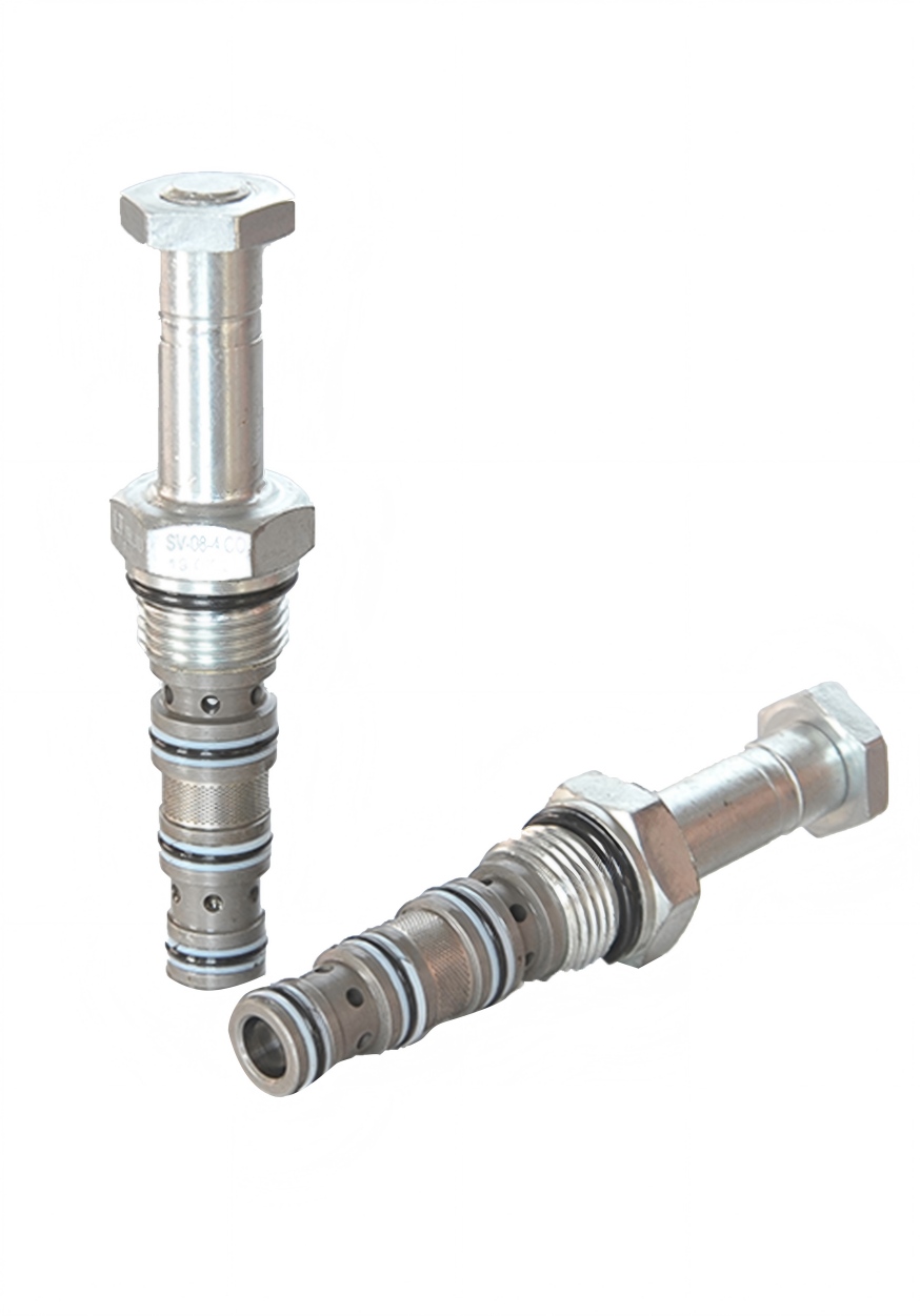
Cartridge Valves
Compact, high-performance valves that provide excellent flow characteristics and can be integrated into complex hydraulic systems.
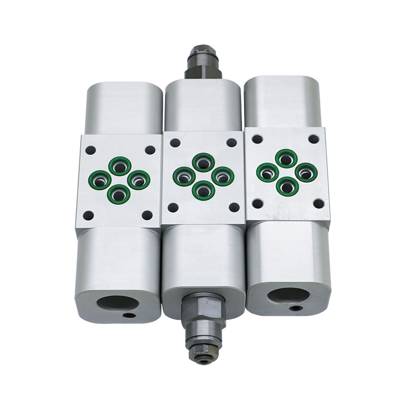
Stack Valves
Modular valve systems that eliminate intermediate piping through direct face-to-face mounting configurations.
Part I: Cartridge Valves - The Foundation of Modern Hydraulic Control
1.1 Fundamental Structure and Operating Principles
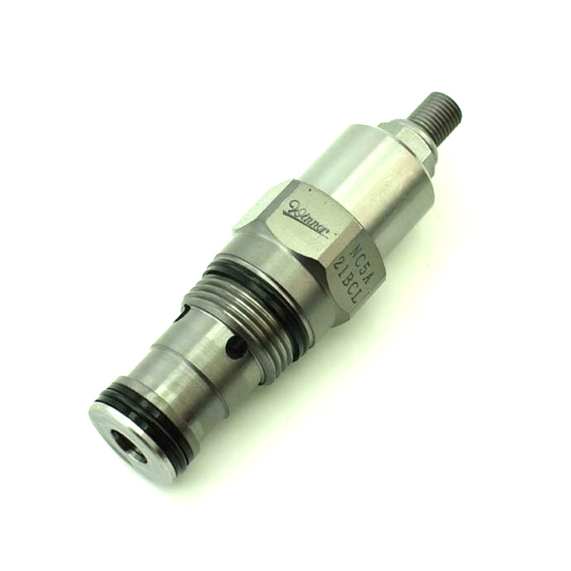
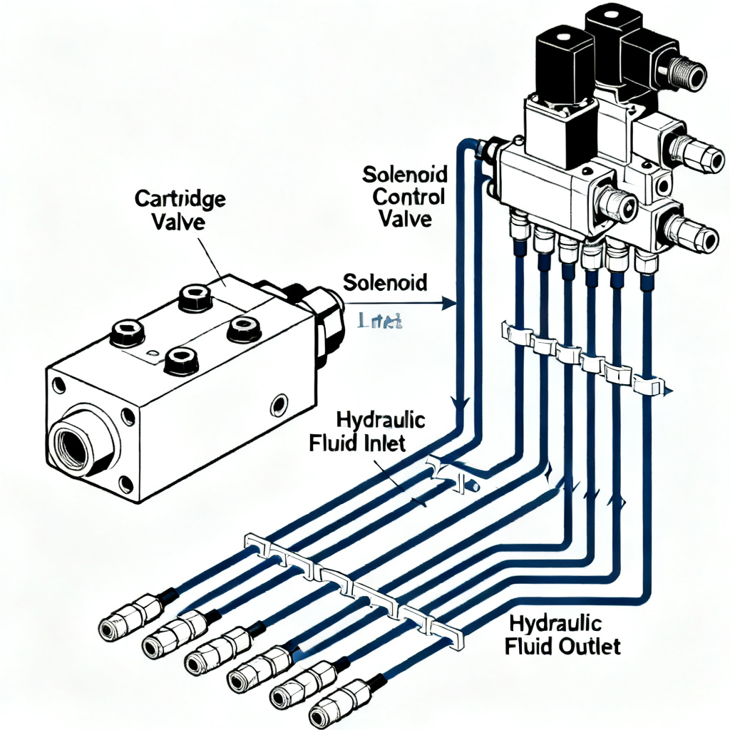
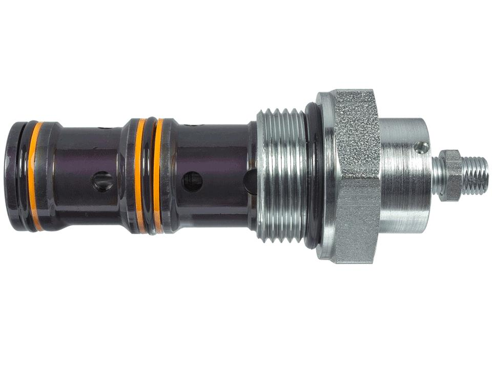
Cartridge valves, also known as two-way insert valves, logic valves, or poppet valves, represent a breakthrough in hydraulic control technology. These valves consist of four primary components: the cartridge insert element, control cover plate integrated with hydraulic solenoid valve systems, pilot control valves, and the manifold block.
The cartridge insert itself typically measures between 16mm to 200mm in diameter, with the most common sizes being 25mm, 32mm, 40mm, 50mm, 63mm, 80mm, and 100mm for industrial applications.
Key Components:
- Cartridge insert element
- Control cover plate with solenoid valve
- Pilot control valves
- Manifold block
Common Sizes (mm):
25
32
40
50
63
80
100
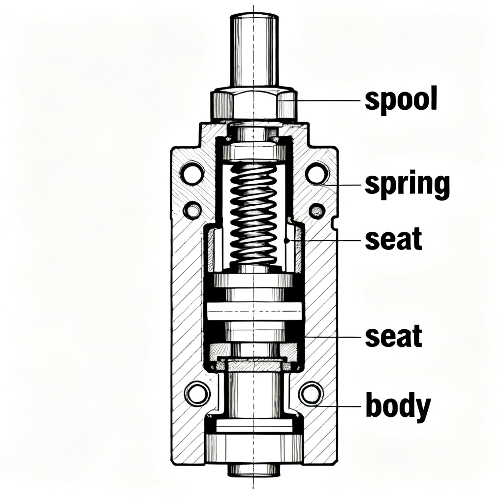
Operating Principle:
The operating principle relies on the force balance equation:
ΣF = pc·Ac - pb·Ab - pa·Aa + Fs + Fy
When ΣF > 0, the valve remains closed; when ΣF < 0, the valve opens.
Force Balance Equation Parameters:
| Parameter | Description | Typical Range |
|---|---|---|
| pc | Control cavity pressure | 0-350 bar |
| Ac | Control cavity area | 12.5-7850 mm² |
| pb, pa | Main port pressures | System dependent |
| Ab, Aa | Corresponding control areas | Design dependent |
| Fs | Spring force | 20-500 N |
| Fy | Flow force | Negligible below 100 L/min |
| α = Ac/Aa | Area ratio | 1.1:1 to 2:1 |
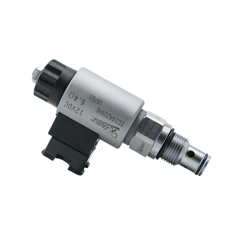
1.2 Advanced Control Mechanisms with Hydraulic Solenoid Valve Integration
The integration of hydraulic solenoid valve technology with cartridge valves has created unprecedented control capabilities. Modern hydraulic solenoid valve systems operating at 12V, 24V, or 110V DC can switch states in as little as 15-30 milliseconds, enabling precise control of cartridge valve operations.
When a hydraulic solenoid valve energizes, it directs pilot flow at rates of 2-20 L/min to control the main cartridge element, which can then handle flows exceeding 3000 L/min.
Solenoid Valve Specifications:
- Voltage: 12V, 24V, or 110V DC
- Switching time: 15-30 milliseconds
- Pilot flow rate: 2-20 L/min
- Control accuracy: ±0.5% position accuracy
- Repeatability: ±0.1% in closed-loop applications
Control Cover Plate Features:
- Tolerances of ±0.01mm
- Sealing capability up to 420 bar
- Integrated micro-pilot elements
- Shuttle valves, check valves, and pressure relief valves
- Nominal sizes of 6mm and 10mm for micro-elements
Proportional Control Capabilities:
The hydraulic solenoid valve control systems can be configured for proportional control, achieving position accuracy of ±0.5% and repeatability of ±0.1% in closed-loop applications. This level of precision enables advanced control strategies in demanding applications.
±0.5%
Position Accuracy
±0.1%
Repeatability
15-30 ms
Response Time
1.3 Performance Characteristics and Technical Specifications
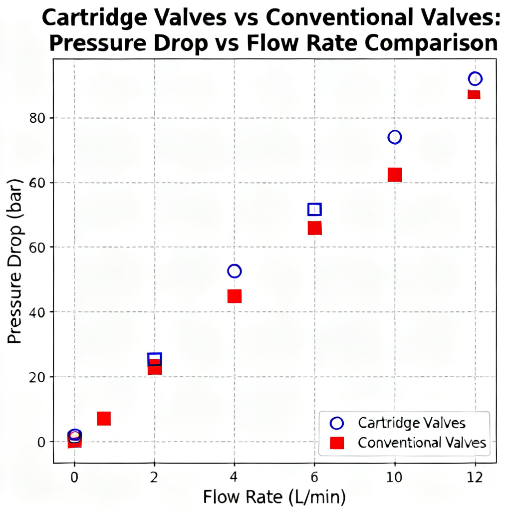
Extensive testing has revealed that cartridge valves exhibit superior flow-pressure characteristics compared to conventional spool valves. At a kinematic viscosity of 30 cSt and temperature of 20°C, a 50mm cartridge valve demonstrates a pressure drop of only 0.8 bar at 500 L/min flow rate, while an equivalent spool valve shows 2.3 bar pressure drop under identical conditions.
Response Time Comparison:
| Cartridge Size | Response Time | Flow Capacity |
|---|---|---|
| Small (16-25mm) | 8 milliseconds | Up to 500 L/min |
| Medium (32-63mm) | 15-25 milliseconds | 500-2000 L/min |
| Large (80-100mm) | 25-50 milliseconds | 2000-5000 L/min |
Temperature Stability:
Modern cartridge valves maintain consistent performance across a wide temperature range when equipped with appropriate sealing materials:
-40°C
Minimum Operating Temp
+120°C
Maximum Operating Temp
Durability and Efficiency:
- 10 million switching cycles at 100% duty cycle
- Some manufacturers guarantee 20 million cycles under optimal conditions
- Leakage rates below 3 drops per minute (≈0.15 mL/min)
- Energy efficiency exceeding 95% in well-designed systems
Pressure Drop Comparison:
0.8 bar
Cartridge Valve
50mm at 500 L/min
vs
2.3 bar
Conventional Valve
Equivalent size
Performance Comparison Chart:
Part II: Directional Control Applications
2.1 Single and Double Acting Configurations
Cartridge valves configured for directional control offer versatility unmatched by traditional valve designs. The simplest configuration involves connecting the control port C to either port A or B, creating a check valve function. When integrated with a hydraulic solenoid valve, this basic configuration transforms into an electrically controlled check valve capable of handling flows up to 4000 L/min with response times under 20 milliseconds.
Single Acting Configuration:
Single acting configurations control flow in one direction only, typically used for applications such as cylinder extension with spring return.
- Flow control in one direction
- Simple design with fewer components
- Ideal for spring-return cylinders
- Lower cost compared to double acting
Double Acting Configuration:
Double acting configurations control flow in both directions, enabling precise control of cylinder extension and retraction.
- Flow control in both directions
- More complex design with additional components
- Ideal for powered extension and retraction
- Higher precision and control capabilities
Configuration Advantages:
4000 L/min
Maximum Flow Rate
<20 ms
Response Time
-40%
Component Reduction
+60%
Switching Speed
Complex Configurations:
More complex arrangements utilize multiple cartridge elements controlled by hydraulic solenoid valve assemblies to create two-position, three-way valves or even four-way valves with up to 12 different operating functions. For instance, a two-position, four-way configuration requires four cartridge inserts and can be controlled by a single hydraulic solenoid valve manifold, reducing component count by 40% compared to conventional designs while improving switching speeds by 60%.
Two-Position, Three-Way Valve
- 3 cartridge inserts
- 1-2 solenoid valves
- Flow capacity: Up to 2000 L/min
- Response time: 15-30 ms
Two-Position, Four-Way Valve
- 4 cartridge inserts
- 2-4 solenoid valves
- Flow capacity: Up to 3000 L/min
- Response time: 20-35 ms
Three-Position, Four-Way Valve
- 4-6 cartridge inserts
- 4 solenoid valves
- Flow capacity: Up to 2500 L/min
- Response time: 25-40 ms
2.2 Advanced Multi-Position Control Systems
The evolution of hydraulic solenoid valve technology has enabled the creation of sophisticated multi-position directional control systems. A three-position, four-way valve assembly utilizing cartridge technology can achieve center conditions including all-ports-blocked, all-ports-open, and various regenerative configurations. When four independent hydraulic solenoid valve units control individual cartridge elements, the system can provide 16 unique flow path combinations, though practical applications typically require only 6-8 configurations.
Three-Position, Four-Way Valve Configurations:
-
All-ports-blocked:
Prevents cylinder movement, holds position
-
All-ports-open:
Cylinder can be moved manually, no hydraulic lock
-
Regenerative:
Fluid from rod end flows to cap end, increasing extension speed
-
Float:
Cylinder follows external forces, no pressure control
-
Pressure-limited:
Controls maximum pressure in one or both directions
Response Time Analysis:
| Flow Capacity | Response Time | Application |
|---|---|---|
| 100-500 L/min | 15-35 milliseconds | Precision control applications |
| 500-2000 L/min | 25-60 milliseconds | Industrial machinery |
| 2000-5000 L/min | 40-80 milliseconds | Large mobile equipment |
Pilot Circuit Characteristics:
10-30 bar
Pilot Pressure
2-5%
Power Consumption
Soft-Shift Features:
Advanced designs incorporate soft-shift features, utilizing pulse-width modulation of the hydraulic solenoid valve signals to achieve precise control over cylinder movement.
0.5-2.0 m/s²
Controlled Deceleration Rate
Flow Path Combinations:
When four independent hydraulic solenoid valve units control individual cartridge elements, the system can provide 16 unique flow path combinations. However, practical applications typically require only 6-8 configurations.
Extend
Retract
Hold
Regenerate
Float
Pressure Limit
Shuttle
Sequence
2.3 Proportional and Servo Control Integration
Modern cartridge valve systems increasingly incorporate proportional and servo control capabilities through sophisticated hydraulic solenoid valve interfaces. These systems achieve positioning accuracy of ±0.02mm in closed-loop applications with update rates of 1000 Hz. The proportional hydraulic solenoid valve controllers generate variable pilot pressures from 0-70 bar, enabling infinite positioning of the main cartridge element within its 2-25mm stroke range.
Proportional Control Capabilities:
-
Positioning Accuracy:
±0.02mm in closed-loop applications
-
Update Rates:
Up to 1000 Hz
-
Pilot Pressure Range:
0-70 bar
-
Stroke Range:
2-25mm (main cartridge element)
-
Control Resolution:
12-16 bit digital-to-analog conversion
Performance Advantages:
35-45%
Efficiency Improvement
Lower
Contamination Sensitivity
18/16/13
ISO Cleanliness Level
10,000+
Hours of Operation
Industry Research Findings:
"The integration of proportional hydraulic solenoid valve technology with cartridge valve systems has demonstrated efficiency improvements of 35-45% compared to conventional servo valve applications, with significantly reduced sensitivity to fluid contamination."
Source: International Fluid Power Society, 2024 (ifps.org)
Systems operating with ISO 4406 cleanliness levels of 18/16/13 show minimal performance degradation over 10,000 operating hours, whereas traditional servo valves require 15/13/10 cleanliness levels for comparable reliability.
Control System Architecture:
| Component | Function | Specifications |
|---|---|---|
| Proportional Solenoid Valve | Generate variable pilot pressure | 0-70 bar, 12-24V DC |
| Cartridge Valve | Control main flow | Up to 5000 L/min, 420 bar |
| Position Sensor | Provide feedback for closed-loop control | ±0.01mm accuracy, 1000 Hz update |
| Electronic Controller | Process feedback and generate control signals | 32-bit processor, 1 MHz clock |
| Amplifier | Drive proportional solenoid valve | 0-5A current output, PWM control |
Part III: Pressure Control Implementations
3.1 Relief and Pressure Reducing Functions
Cartridge valves excel in pressure control applications when combined with appropriate hydraulic solenoid valve pilot circuits. Relief valve configurations utilize damped poppet designs with orifice diameters of 1.0-3.0mm, enabling stable pressure control from 10-420 bar with hysteresis less than 2%. The hydraulic solenoid valve pilot stage typically operates at 1/30 to 1/50 of the main flow capacity, maintaining pressure regulation accuracy of ±1% across flow ranges from 10% to 100% of rated capacity.
Relief Valve Configurations:
-
Damped Poppet Design:
Orifice diameters of 1.0-3.0mm
-
Pressure Range:
10-420 bar
-
Hysteresis:
Less than 2%
-
Pilot Flow Ratio:
1/30 to 1/50 of main flow capacity
-
Pressure Regulation Accuracy:
±1% across 10-100% flow range
Pressure Reducing Valve Features:
-
Pressure Stability:
±0.5 bar despite ±50 bar upstream variation
-
Response Time:
50-100 milliseconds for step changes
-
Steady-State Accuracy:
Achieved in under 200 milliseconds
-
Electronic Feedback:
0.25% accuracy class pressure transducers
-
Long-Term Stability:
Better than ±0.1% of full scale
Pressure Control Performance:
±1%
Regulation Accuracy
<2%
Hysteresis
±0.5 bar
Stability
420 bar
Max Pressure
Pressure vs. Flow Characteristic:
Application Examples:
Hydraulic Presses
Precise pressure control for forming operations, maintaining consistent force throughout the stroke.
Injection Molding
Accurate pressure regulation for injection and holding phases, ensuring part quality consistency.
Mobile Equipment
Stable pressure control for various implements, adapting to changing loads and conditions.
3.2 Sequential and Unloading Valve Applications
Sequential control systems utilizing cartridge valves provide reliable operation in multi-actuator applications. The hydraulic solenoid valve controls enable precise sequencing with adjustable time delays from 0.1 to 10 seconds and pressure thresholds settable in 1 bar increments. Typical industrial applications involve 2-8 sequential stages, each controlled by dedicated hydraulic solenoid valve circuits operating independently or in coordinated patterns.
Sequential Control Systems:
-
Time Delays:
Adjustable from 0.1 to 10 seconds
-
Pressure Thresholds:
Settable in 1 bar increments
-
Sequential Stages:
Typically 2-8 stages in industrial applications
-
Control Architecture:
Dedicated solenoid valve circuits per stage
-
Operation Modes:
Independent or coordinated control patterns
Sequential Control Applications:
Material Handling
Controlled movement of robotic arms, conveyors, and lifting devices in a precise sequence.
Assembly Lines
Coordinated actuation of multiple tools and fixtures in assembly processes.
Machine Tools
Sequential operation of clamps, feeds, and cutting tools in machining centers.
Unloading Valve Benefits:
60-80%
Energy Savings
<5 bar
Idle Pressure
20-40 ms
Response Time
<110%
Pressure Spike
Soft-Unloading Features:
Advanced designs incorporate soft-unloading features, gradually reducing system pressure over time to minimize shock loads on pumps and prime movers.
0.5-2.0 seconds
Pressure Reduction Time
Sequential Control Diagram:
Sequential Control System Diagram
Stage 1 → Stage 2 → Stage 3 → Stage 4
3.3 Multi-Stage Pressure Control Systems
Complex pressure control requirements often necessitate multi-stage configurations combining multiple cartridge elements with sophisticated hydraulic solenoid valve networks. Two-stage and three-stage pressure control systems provide discrete pressure levels with transition times of 30-60 milliseconds between stages. Each stage typically offers independent adjustment ranges spanning 50-350 bar, with overlap capabilities ensuring smooth transitions.
Multi-Stage System Characteristics:
-
Stage Configuration:
Two-stage and three-stage systems common
-
Transition Times:
30-60 milliseconds between stages
-
Pressure Ranges:
50-350 bar per stage, independent adjustment
-
Transition Characteristics:
Overlap capabilities for smooth transitions
-
Control Precision:
±1% of set pressure per stage
System Power Requirements:
15-30 W
Per Solenoid Valve
150+ kW
Main Flow Power
100-500 Hz
PWM Frequency
<0.5%
Hysteresis
Temperature Compensation:
Temperature compensation algorithms adjust hydraulic solenoid valve drive currents to maintain consistent performance across a wide range of ambient conditions.
-20°C
Minimum Ambient Temp
+80°C
Maximum Ambient Temp
Multi-Stage Pressure Profile:
Application Examples:
Plastic Injection Molding
Different pressure stages for injection, packing, and holding phases, with precise transition control.
Metal Forming
Multiple pressure levels for different forming operations, optimizing material flow and part quality.
Testing Equipment
Programmed pressure cycles for component testing, simulating real-world operating conditions.