
Here’s what trips up most engineers when they first encounter hydraulic flow meters: they assume these instruments measure volume the same way a graduated cylinder does. Spoiler—they don’t. Hydraulic flow meters measure something fundamentally different, and understanding that distinction is what separates effective troubleshooting from expensive guesswork.
The short answer? Hydraulic flow meters measure volumetric flow rate—the volume of fluid passing through a point per unit of time, typically expressed in gallons per minute (GPM) or liters per minute (LPM). They don’t measure static volume. Think of it this way: a flow meter tells you how fast your hydraulic “bathtub” is filling, not how full it is.
But that simple explanation masks a deeper reality about how these instruments work, why the distinction matters for system performance, and what happens when you misunderstand the difference. Three years ago, I watched a maintenance team spend $12,000 replacing a perfectly functional hydraulic pump because they confused flow rate readings with volume measurements. The pump was fine—they just didn’t understand what their flow meter was telling them.
Most hydraulic flow meters generate one of three types of data: instantaneous flow rate, accumulated volume over time, or both. Here’s where the confusion starts.
When you see “GPM” on your meter’s display, you’re looking at a rate measurement—a derivative of volume with respect to time. This is fundamentally different from the “gallons” your reservoir holds. According to research published by the Fluid Power World technical team, flow rate in hydraulic systems is analogous to electrical current, while pressure corresponds to voltage. Measuring one without the other creates an incomplete diagnostic picture.
The mathematics behind this relationship is straightforward but crucial:
Volumetric Flow Rate (Q) = Cross-sectional Area (A) × Average Velocity (v)
For a pipe with constant diameter, if fluid velocity doubles, flow rate doubles. But the volume of fluid in that pipe section at any instant? That stays the same. This is the heart of the flow-volume distinction that causes so much confusion on shop floors.
The mechanism depends entirely on the meter type, but all hydraulic flow meters ultimately convert physical motion or displacement into flow rate data. Let’s break down the three dominant technologies:
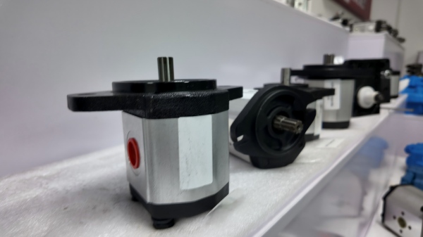
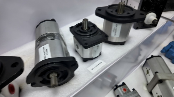
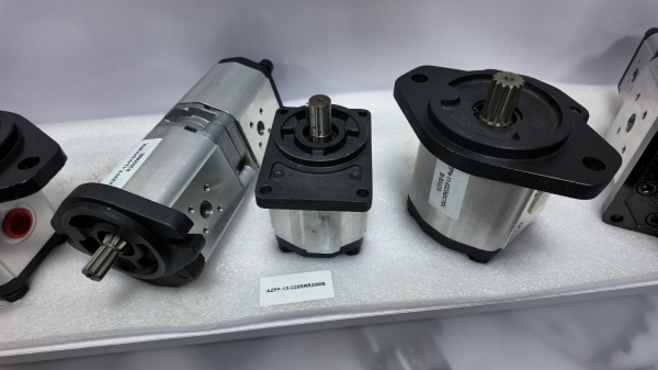
Positive Displacement Meters (including oval gear and helical gear designs) trap discrete fluid volumes in chambers. Each chamber rotation represents a known volume—say, 0.5 cubic inches. A transducer counts rotations. At 1,000 RPM, that’s 500 cubic inches per minute of flow. The meter isn’t measuring volume; it’s counting discrete volume “packets” moving past a point and calculating rate from that count.
The beauty of positive displacement? They remain accurate across viscosity ranges that would cripple other technologies. Data from AW-Lake Company shows these meters maintain ±0.5% accuracy even when measuring fluids with viscosities ranging from 5 to 500,000 cSt—a hundred-thousand-fold difference.
Turbine Flow Meters spin a rotor at a rate proportional to fluid velocity. Here’s where the physics gets interesting. The rotation speed gives you velocity, but you need to know the pipe’s cross-sectional area to calculate volumetric flow rate. A 2-inch pipe flowing at 10 feet per second delivers 13.6 GPM; the same velocity in a 1-inch pipe? Only 3.4 GPM. The meter measures velocity and calculates flow rate using the known pipe geometry.
Variable Orifice Meters use fluid momentum to displace a piston or float against spring resistance. Displacement distance correlates to flow rate, typically with 2-5% full-scale accuracy according to Webtec specifications. These are the workhorses for field troubleshooting—simple, rugged, and they work without power.
Here’s where flow meters reveal their versatility. Modern digital units can integrate flow rate over time to display total volume delivered. If your system pumps 25 GPM for 10 minutes, the integrated volume is 250 gallons—but the meter was measuring rate the entire time, then performing the calculation V = Q × t.
This integration feature confuses people. They see “gallons” on the display and assume the meter measures volume. It doesn’t. It measures flow rate, then mathematically accumulates that rate into a volume figure. The distinction matters because measurement errors compound differently for rate versus integrated volume.
In 2024, Titan Enterprises published research on precision flow measurement challenges in hydraulic systems. Their findings revealed something troubling: temperature fluctuations throughout a single work shift can alter fluid viscosity enough to throw volumetric calculations off by 15% if you’re using the wrong meter technology.
Here’s the practical reality: when diagnosing hydraulic system performance, you need both flow rate and total volume data, but for different purposes.
Instantaneous flow rate reveals pump degradation, valve restrictions, and leakage paths. A hydraulic pump rated for 20 GPM that’s delivering 17 GPM has a problem—even if the total volume delivered over an hour seems acceptable. That 15% reduction might indicate worn internal components, contaminated fluid increasing viscosity, or a pressure relief valve creeping open.
According to data from Hydracheck flow meter applications, pump efficiency degradation typically presents as gradually declining flow rate at constant pressure. A system that required 5 hours to complete a task at installation but now requires 6.5 hours? The flow rate has dropped even if the total volume moved remains identical.
Accumulated volume matters for different reasons. In batch processing, you need to deliver specific fluid quantities. A hydraulic press cycle might require 42 gallons to complete—no more, no less. Here, integrated volume from flow rate measurements ensures process consistency.
But there’s a catch. If your flow meter accumulates volume by integrating instantaneous flow rate (Q × time), any systematic error in rate measurement compounds linearly. A meter reading 3% high on flow rate will accumulate volume measurements 3% high. Over a 1,000-gallon batch, that’s 30 gallons of error—potentially scrapping expensive product.
This is why industry standards from organizations like the International Society of Automation specify different accuracy requirements for flow rate versus integrated volume applications. Flow rate accuracy typically runs ±0.5% to ±2% of reading, while accumulated volume calculations inherit that error plus any timing inaccuracies.
Hydraulic oil viscosity drops roughly 50% for every 25°F temperature increase. On a cold morning start (40°F oil), your hydraulic fluid might exhibit 220 cSt viscosity. After an hour of operation (150°F), that same oil drops to 15 cSt.
For turbine meters, this viscosity swing can introduce 8-12% measurement error if not compensated. Why? The relationship between fluid velocity and turbine rotation rate changes with Reynolds number, which depends on viscosity. Data from Sino-Inst’s technical documentation shows uncorrected turbine meters can under-report flow by 10% when measuring cold, high-viscosity oil compared to hot, thin oil at the same actual flow rate.
Positive displacement meters largely avoid this problem. The gear chambers displace the same volume regardless of viscosity—though at extreme viscosities (above 100,000 cSt), even PD meters show some slip past the gear teeth.
Modern hydraulic flow meters pack a lot of information into compact displays, but interpreting that data requires understanding what you’re looking at. Let me walk through what’s actually happening when you connect a flow meter to test a hydraulic pump.
Quality hydraulic flow meters typically show three simultaneous readings:
1. Instantaneous Flow Rate (GPM or LPM) This updates multiple times per second, showing real-time rate. But here’s what most people miss: that number represents an average over the meter’s response time. A gear meter counting tooth passages at 1,000 Hz might display a flow rate averaged over the past 0.1 seconds. For steady flow, this doesn’t matter. For pulsating flow from certain pump types, you might see ±20% fluctuation in the displayed rate even though average flow stays constant.
2. System Pressure (PSI or bar) Essential because flow rate alone tells an incomplete story. Twenty GPM at 500 PSI indicates healthy pump output. Twenty GPM at 2,800 PSI? Your pump is working way too hard, possibly compensating for internal leakage or system restrictions. The pressure reading contextualizes the flow measurement.
3. Fluid Temperature (°F or °C) This number deserves more attention than it gets. As discussed, temperature affects viscosity, which affects measurement accuracy on most meter types. Advanced meters use temperature input to apply real-time viscosity compensation. Basic meters just display temperature as reference data—you have to know what to do with it.
Many digital flow meters include a totalizer displaying accumulated volume since last reset. This is calculated, not measured. The meter integrates flow rate over time using the formula:
Total Volume = ∑(Flow Rate × Time Interval)
If you test a pump for 5 minutes at a displayed 22.3 GPM, the totalizer should show approximately 111.5 gallons. If it shows 95 gallons, either the flow rate reading is wrong, there’s a timing issue in the integration algorithm, or (most commonly) the flow wasn’t actually steady at 22.3 GPM the entire time.
This is where experience separates good troubleshooters from great ones. I watched a field tech spend two hours convinced his flow meter was broken because totalizer volume didn’t match manual calculations. Turned out the pump he was testing had severe cavitation—flow rate was dropping to 8 GPM every 15 seconds when pressure spiked. The instantaneous display showed this clearly, but he was fixated on the totalizer mismatch.
Understanding how different meter types generate their measurements fundamentally changes how you interpret their readings. Each technology has sweet spots and blind spots that aren’t obvious from spec sheets.
PD meters operate on an elegantly simple principle: trap known volumes, count them, multiply by time to get rate. Inside an oval gear meter, two elliptical gears rotate at 90° to each other, sweeping crescent-shaped fluid chambers around their perimeter.
Each complete rotation displaces a precisely known volume—typically calibrated at the factory and laser-etched onto the meter body. A magnetic pickup senses gear tooth passage; the electronic transducer converts this to flow rate. At 500 RPM with a 2 mL per revolution displacement, you’re looking at 1,000 mL/min or about 0.26 GPM.
The key advantage? PD meters measure actual displaced volume, making them largely immune to viscosity changes, density variations, and flow profile distortions. The gears physically capture and count fluid volume. Contamination is their nemesis—a single piece of debris lodged between gear teeth can stop the meter or cause catastrophic wear.
Market data from Grand View Research shows PD meters maintaining ±0.5% accuracy across fluid viscosities from 0.5 to 500,000 cSt. That’s why they dominate custody transfer applications where you’re quite literally measuring how much money is flowing through the pipe.
Turbine meters put a miniature windmill in your fluid stream. Flow spins the rotor; rotor speed indicates velocity; velocity times pipe area equals volumetric flow rate.
Here’s the gotcha: the velocity-to-rotation relationship isn’t perfectly linear. At very low flows, bearing friction affects rotation. At high flows, turbulence and blade angle effects come into play. Most turbine meters specify a “linear range” of 10:1 or 20:1—meaning maximum rated flow divided by minimum accurate flow.
For a 0.5-50 GPM meter, don’t expect accurate readings below 2.5 GPM. The turbine is spinning, but friction losses and non-linear response in the low-flow regime throw off the velocity calculation. This is why turbine meters excel at monitoring relatively steady, mid-to-high flow rates but struggle with batch filling applications where flow starts at zero and ramps up.
According to Webtec’s engineering documentation, turbine meters can achieve ±1% accuracy in their linear range, but that assumes clean fluid, stable temperature, and flow velocities that keep the Reynolds number above 4,000. Drop below that, and you’re in transitional or laminar flow regimes where the turbine’s response changes character.
These are the analog workhorses—no electronics, no power required, just physics. Fluid flows through a tapered orifice, pushing a piston or float against spring resistance. Higher flow rate means higher fluid momentum, which compresses the spring further. A magnetic coupling translates piston position to pointer rotation on an analog dial.
The beauty is simplicity and ruggedness. I’ve seen variable orifice meters survive being run over by forklifts, submerged in mud, and dropped from second-story catwalks—then work perfectly after a quick rinse. The downside? Accuracy typically runs 2-5% full scale, and you’re reading an analog dial, which introduces human parallax errors.
Sharp-edged orifice design in quality meters (like those from Hedland) minimizes viscosity effects. The fluid essentially “cuts” through the orifice at sharp edges, making the pressure drop less dependent on viscosity than you’d expect from theory. Still, extreme viscosity changes (0°F startup in winter versus 180°F summer operation) can shift readings by 10% if uncorrected.
Let’s address the elephant in the room: sometimes people say “measure volume” when they actually mean “determine total volume delivered.” This isn’t wrong—it’s just imprecise terminology that causes confusion.
When a technician says “I need to measure how much volume this pump delivers,” they’re really asking: “How much total fluid does this pump move in a given time?” That’s a valid question, but it requires measuring flow rate and multiplying by time, not directly measuring volume.
If you want to truly measure volume directly—no flow rate calculations involved—you collect fluid in a calibrated container. This is the “bucket test” that field techs have used for decades when flow meters aren’t available.
Connect a hose to your pump outlet. Run it into a 5-gallon bucket. Time how long it takes to fill. If 5 gallons takes 15 seconds, your flow rate is:
Flow Rate = Volume ÷ Time = 5 gallons ÷ 0.25 minutes = 20 GPM
Notice what happened? You measured volume (5 gallons, marked on your bucket) and time (15 seconds), then calculated flow rate. This is the inverse of what a flow meter does—the meter measures rate, then integrates over time to calculate volume.
The bucket test has problems. It’s messy, dangerous (pressurized oil spraying into buckets tends to go sideways), and you’ve now contaminated 5 gallons of fluid that needs filtering before it goes back in the system. But it demonstrates the distinction perfectly: volume is a static measurement of quantity, flow rate is a dynamic measurement of change.
Digital flow meters blur this distinction by displaying both instantaneous rate and accumulated total. From a user standpoint, this is ideal—you get the diagnostic power of real-time flow rate plus the accountability of total volume delivered.
But understand what’s happening under the hood. The meter’s sensor (gear teeth, turbine blade, orifice displacement) measures a rate parameter. The microprocessor converts that to volumetric flow rate. If you want accumulated volume, the processor numerically integrates: V = ∫Q dt, sampling flow rate perhaps 100 times per second and summing the results.
This integration approach has accuracy implications. Integration errors accumulate. If your meter samples flow rate with ±1% random error, and you integrate over 1,000 samples, statistical theory says your accumulated volume should still be within ±1% if errors are truly random. But systematic errors (like temperature-induced bias in a turbine meter) accumulate linearly.
Modern meters from manufacturers like Emerson and Siemens include temperature compensation algorithms, viscosity correction factors, and multi-point linearization curves stored in firmware. The market for these “smart” flow meters reached $12.36 billion in 2025 according to Research Nester, driven largely by industries where measurement accuracy directly affects profitability—oil and gas custody transfer, pharmaceutical batch processing, food and beverage manufacturing.
Theory is great, but let’s talk about what actually happens when you’re standing in front of a malfunctioning hydraulic system with a flow meter in hand.
Hydraulic pumps fail gradually, not catastrophically (usually). Internal wear causes increasing slip—fluid leaking internally past seals and clearances instead of being pushed out the discharge port. This manifests as declining flow rate at constant input speed.
Your pump is stamped “20 GPM at 1,800 RPM and 1,500 PSI.” You hook up your flow meter, spin the pump to 1,800 RPM, load it to 1,500 PSI with your flow meter’s load valve, and read… 16.5 GPM. The pump has lost 17.5% of its rated capacity.
That’s a flow rate measurement revealing pump degradation. If you were trying to diagnose this by measuring volume—say, filling a known reservoir and timing it—you’d get the same information, but less precisely and with more work. The flow meter’s real-time rate display lets you immediately see the problem.
Here’s the subtle part: the 3.5 GPM you’re missing? It’s still inside the pump, circulating internally through worn clearances. The pump is moving the same total volume, but less of it exits the discharge port. This is why measuring output flow rate tells you more about pump health than measuring input volume.
Flow restrictors, clogged filters, kinked hoses—all these show up instantly in flow rate measurements but would be harder to detect via total volume accounting.
Run your flow meter inline. Flow drops from 22 GPM to 12 GPM when you open a specific valve? That valve or its downstream circuit has a restriction. The volume of fluid in the circuit hasn’t changed—it’s still a 10-gallon system whether flow is 22 GPM or 12 GPM. But the rate at which you can move fluid through it has been cut in half.
Experienced hydraulic techs use flow meters to map entire systems, measuring flow at every junction point. Flow entering a four-way valve: 20 GPM. Flow exiting to cylinder: 18 GPM. Where’d the other 2 GPM go? Internal leakage past valve seals, now revealed by comparing flow rates at different measurement points.
Cold starts kill flow meter accuracy. Hydraulic oil at 40°F might be 10-50 times more viscous than the same oil at 150°F operating temperature. This affects measurement differently depending on meter type:
Professional flow meters include temperature sensors and apply correction algorithms. Budget meters just display temperature—you’re expected to know what to do with that information. The practical reality? If you’re doing critical measurements (pump acceptance testing, performance verification, custody transfer), let the system warm up to operating temperature before relying on flow meter data.
Volumetric flow rate measures volume per time (gallons per minute), while mass flow rate measures mass per time (pounds per hour). For incompressible hydraulic fluids, volume and mass are directly related through fluid density: mass flow = volumetric flow × density. Most hydraulic applications use volumetric measurement because oil density stays relatively constant. In aerospace or high-temperature applications where density varies significantly, mass flow meters (usually Coriolis-type) become important.
No. Flow meters measure how fast fluid is moving past a point, not how much fluid exists in a container. To determine reservoir level, you need a level sensor (float switch, ultrasonic, capacitive, etc.). However, if you know your reservoir started empty and you measure all flow into it with a flow meter’s totalizer function, you can calculate current level: volume added minus volume removed.
Pulsation from the pump, pressure waves in the system, and genuine flow variations all cause reading fluctuations. Piston pumps generate inherently pulsating flow—up to ±30% instantaneous variation around the average. Most digital meters include damping or averaging functions to smooth displayed values. If fluctuations exceed ±10% on a supposedly steady system, investigate: cavitation, worn pump components, or air entrainment are common causes.
Depends entirely on meter type. Positive displacement meters maintain accuracy across the widest viscosity range (0.5 to 500,000 cSt for quality units). Turbine meters lose accuracy above 100 cSt and below 1 cSt. Variable orifice meters, with sharp-edged designs, work reasonably well from 5 to 5,000 cSt. For hydraulic applications using ISO VG 32-68 oils (the most common), all three types work fine at operating temperature. At cold startup, PD meters have the advantage.
Not for the flow rate number itself—20 GPM is 20 GPM whether at 500 PSI or 3,000 PSI (assuming incompressible fluid). But pressure and flow together tell the system performance story. High flow at low pressure suggests unrestricted flow paths and healthy pump. Low flow at high pressure suggests restrictions or pump problems. The flow meter measures rate; pressure measurement provides context for what that rate means.
Some can, some can’t. Bidirectional flow meters (often using dual turbines or bidirectional gear designs) explicitly measure flow in both directions and typically display direction along with rate. Unidirectional meters often include check valves that prevent reverse flow—attempting to flow backward through them can damage the mechanism. If you’re testing double-acting cylinders or reversible motors, verify your flow meter supports bidirectional measurement.
Industry standards (ISO 4185) typically recommend annual calibration for custody transfer applications where accuracy directly affects commerce. For troubleshooting and maintenance use, calibration every 2-3 years is usually sufficient if the meter hasn’t been damaged. Signs you need recalibration: the meter has been impacted, exposed to contaminated fluid, or its readings don’t match a known-good reference when testing the same pump. Many facilities maintain a “master” meter with current calibration certificate and use it to verify field meters periodically.
Armed with this understanding, let’s talk about choosing measurement approaches for common hydraulic scenarios.
You need instantaneous flow rate at specified pressure. Connect a flow meter inline with integrated pressure measurement (or separate pressure gauge teed into the circuit). Load the pump to spec pressure using the meter’s load valve. Read flow rate directly. The meter is measuring rate, which is exactly what pump specs reference. Bonus: modern digital meters can log data, capturing flow rate variation over time to reveal problems like cavitation or periodic internal leakage.
You need accumulated volume with good accuracy. Use a flow meter with totalizer function and let it integrate flow rate over time. Better yet, use a PD meter—since it’s actually counting discrete volume packets, integration errors are minimal. Reset the totalizer at batch start, begin flow, stop when totalizer reaches target volume. For critical applications, verify periodically with gravimetric measurements (weigh the delivered fluid) to catch systematic errors.
You need flexible, real-time rate information. Portable flow meters with analog displays work great here—quick to install, easy to read, no calibration concerns if you’re comparing relative measurements. The absolute accuracy might be ±5%, but that’s fine when you’re trying to find which of six hydraulic motors is consuming more flow than it should. Compare flow in versus flow out; differences reveal leakage paths.
Smart digital meters with data logging and remote communication capabilities make sense. These meters continuously measure flow rate and can alert you to trends: gradually declining average flow (pump wear), increasing flow variation (developing cavitation), unexpected flow when the system should be idle (external leakage). They’re measuring rate, but the real value is pattern recognition over time.
Hydraulic flow meters measure volumetric flow rate—volume per unit time. They don’t directly measure the volume of fluid in a system any more than a speedometer directly measures the distance you’ve traveled. But just as a speedometer integrated over time (speed × time = distance) tells you how far you’ve gone, a flow meter integrated over time (flow rate × time = volume) tells you how much fluid has passed through.
The distinction matters because flow rate reveals system dynamics—pump health, restriction locations, leakage paths—that static volume measurements would miss. When that maintenance team I mentioned earlier finally understood their flow meter was showing pump output rate, not reservoir volume, they quickly diagnosed the actual problem: a partially closed valve reducing system flow by 30%. The pump was fine. They just hadn’t asked the right question of their measurement tool.
Modern hydraulic flow meters excel at measuring what matters most: how fast your system is moving fluid and, if needed, how much total fluid it’s moved. Understanding what they actually measure—and what they don’t—transforms these instruments from confusing black boxes into powerful diagnostic tools that pay for themselves the first time they prevent an unnecessary pump replacement.
Key Takeaways
Recommended Next Steps
If you’re specifying a flow meter, start by defining what you actually need to know: instantaneous system performance (flow rate) or total fluid delivered (integrated volume). For troubleshooting hydraulic systems, invest in a quality portable flow meter with integrated pressure measurement—preferably a positive displacement type if you’re working with widely varying fluid temperatures. And most importantly, make sure everyone on your team understands that when the meter displays “GPM,” it’s not telling you how many gallons you have—it’s telling you how fast those gallons are moving.
Data sources: Fluid Power World (fluidpowerworld.com), Grand View Research (grandviewresearch.com), Research Nester (researchnester.com), Emerson Electric Co. (emerson.com), Titan Enterprises (flowmeters.co.uk), Webtec (webtec.com), Sino-Inst (sino-inst.com), AW-Lake (aw-lake.com)