
Hydraulics operates on three fundamental scientific principles: Pascal’s Law, which states that pressure applied to a confined fluid transmits equally in all directions; the incompressibility of liquids, which allows efficient force transmission; and Bernoulli’s Principle, which describes the relationship between fluid velocity, pressure, and elevation. These principles work together to enable hydraulic systems to multiply forces and transmit power through fluids.
The entire field of hydraulics rests on a basic physical property of liquids—they resist compression. Unlike gases, which can be squeezed into smaller volumes, liquids maintain nearly constant density even under tremendous pressure. This characteristic creates the conditions necessary for reliable power transmission.
When force is applied to a liquid in a confined space, the liquid cannot shrink or expand significantly. Instead, it transmits that force through its molecular structure. Water molecules, for instance, are already tightly packed in their liquid state. Applying pressure simply forces these molecules against their neighbors, creating a chain reaction that carries the force throughout the entire fluid volume.
This property distinguishes hydraulics from pneumatics. Gas-based systems experience compressibility losses—energy gets absorbed as the gas compresses before any useful work happens. Hydraulic systems avoid this inefficiency. The force you apply at one point appears almost instantaneously at another point, with minimal energy lost to fluid compression.
Practical systems use oils rather than water because petroleum-based fluids offer better lubrication and corrosion resistance. However, the incompressibility principle remains the same across all hydraulic fluids. Whether using mineral oil, synthetic fluids, or water-based alternatives, the fluid’s resistance to volume change enables predictable force transmission.
Blaise Pascal formulated the principle that defines hydraulic force multiplication in the 1650s. Pascal’s Law states that pressure applied to any point in a confined fluid at rest transmits undiminished to all other points in the fluid. More precisely, when you change the pressure at one location, that pressure change propagates throughout the entire fluid volume, reaching every surface in contact with the fluid.
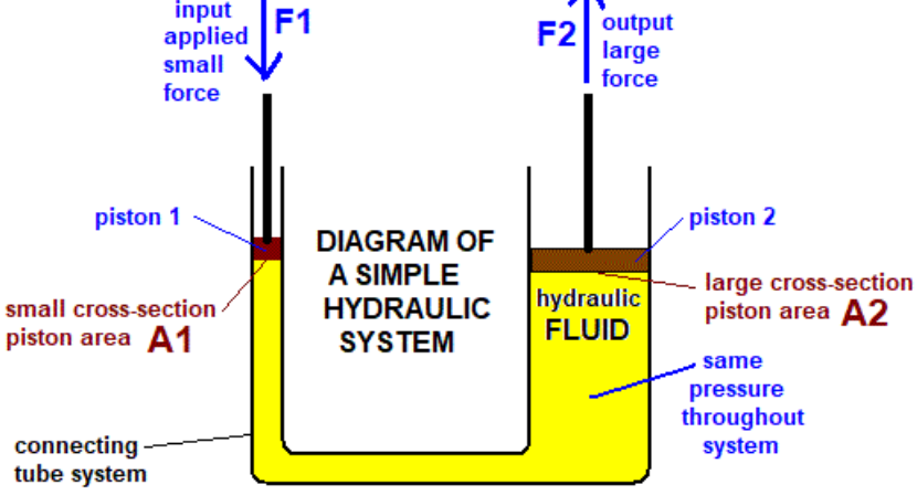
The mathematical expression is straightforward: Pressure equals force divided by area (P = F/A). This simple relationship unlocks tremendous mechanical advantage. Consider a hydraulic system with two connected cylinders of different sizes. Apply 100 newtons of force to a small piston with an area of 1 square centimeter, creating a pressure of 100 N/cm². That pressure transmits through the fluid to a larger piston with an area of 10 square centimeters. Since pressure remains constant throughout the system, the larger piston experiences 1,000 newtons of force—ten times the input force.
The system doesn’t create energy from nothing. What you gain in force, you lose in distance. If the small piston moves 10 centimeters, the large piston moves only 1 centimeter. The work done (force times distance) stays constant, minus friction losses. This trade-off between force and distance mirrors how mechanical levers work, but hydraulic systems offer advantages in terms of flexibility and design freedom.
Pascal’s principle explains why hydraulic brakes function so effectively. The driver’s foot applies modest force to a small master cylinder. That pressure reaches brake cylinders at all four wheels simultaneously, applying strong clamping force to the brake pads. The system distributes force evenly without complex mechanical linkages.
The “undiminished” aspect of Pascal’s Law merits emphasis. In ideal conditions, pressure loss is zero as it travels through the fluid. Real systems experience some pressure drop due to friction in hoses and valves, but these losses are relatively small compared to the forces involved. This efficiency makes hydraulic power transmission practical over considerable distances.
Daniel Bernoulli published his principle in 1738, establishing that the total mechanical energy in a flowing fluid remains constant along a streamline. This principle extends hydraulic analysis beyond static pressure to include dynamic flow conditions. The equation balances three forms of energy: pressure energy, kinetic energy (related to velocity), and potential energy (related to elevation).
In mathematical form, Bernoulli’s equation states that P + ½ρv² + ρgh = constant, where P represents pressure, ρ is fluid density, v is velocity, g is gravitational acceleration, and h is height. This equation tells us that as fluid velocity increases, pressure decreases, and vice versa. Similarly, as fluid flows uphill, either its pressure or velocity must decrease to maintain energy balance.
Hydraulic system designers use Bernoulli’s principle to predict behavior in variable-diameter pipes and channels. When fluid flows from a wide pipe into a narrow section, it must accelerate to maintain the same volume flow rate. This acceleration comes at the cost of pressure. The narrow section experiences lower static pressure than the wide section, even though the same amount of fluid passes through both areas per unit time.
This principle explains cavitation in hydraulic pumps and valves. When local pressure drops below the fluid’s vapor pressure, bubbles form. These bubbles collapse violently when they move into higher-pressure regions, causing damage to metal surfaces. Proper hydraulic system design accounts for Bernoulli’s principle to keep pressures above critical thresholds throughout the circuit.
The principle also governs flow measurement. Venturi meters and orifice plates create deliberate restrictions in pipes. By measuring the pressure difference between the unrestricted and restricted sections, engineers calculate flow rate using Bernoulli’s equation. The relationship between pressure drop and flow velocity makes these simple devices remarkably accurate.
Bernoulli’s principle operates within important constraints. It assumes steady flow, incompressible fluid, and negligible viscosity. Real hydraulic systems include friction, which Bernoulli’s original equation doesn’t account for. Engineers add loss terms to the equation to represent energy dissipated as heat through friction in pipes, fittings, and valves.
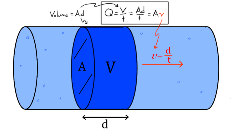
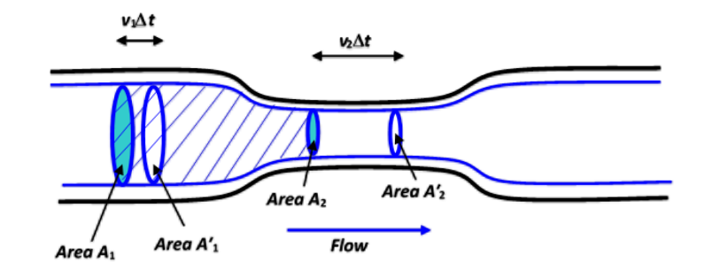
The continuity equation complements Bernoulli’s principle by asserting that mass flow rate remains constant throughout a hydraulic system. For incompressible fluids, this translates to constant volume flow rate. The product of cross-sectional area and flow velocity stays the same at every point in the system: A₁v₁ = A₂v₂.
This principle explains why fluid velocity increases in constricted sections. If a pipe narrows to half its original diameter, the cross-sectional area decreases to one-quarter. To maintain the same volume flow rate, velocity must increase by a factor of four. This acceleration happens automatically, driven by pressure differences described by Bernoulli’s principle.
The continuity equation ensures hydraulic cylinders extend at predictable speeds. Pump output volume per revolution determines how quickly fluid arrives at the cylinder. The cylinder’s piston area determines how far it extends per unit volume of fluid received. Doubling the piston area halves the extension speed for the same pump output. This relationship allows precise control of actuator speed by regulating either pump flow or cylinder geometry.
Leakage violates the continuity equation. In an ideal sealed system, every drop of fluid entering one end emerges at the other. Real systems lose small amounts through seal gaps and wear. These losses reduce system efficiency and can cause performance problems if they grow excessive. Maintaining seal integrity preserves the continuity relationship that makes hydraulic systems predictable.
Hydraulic systems manipulate the relationship between pressure, force, and area to achieve desired mechanical outputs. The fundamental equation P = F/A can be rearranged as F = P × A, revealing that force equals pressure multiplied by area. This direct proportionality enables engineers to design systems that produce precisely calibrated forces.
Consider the pressure unit itself. One pascal equals one newton per square meter—a small pressure by hydraulic standards. Industrial hydraulic systems typically operate between 700 psi (approximately 5 MPa or 50 bar) and 3,000 psi (approximately 20 MPa or 200 bar). At 1,000 psi, a cylinder with a 10-square-inch piston area generates 10,000 pounds of force. The same pressure applied to a 100-square-inch piston produces 100,000 pounds of force.
This scalability allows a single pump to power multiple actuators of different sizes. Each actuator receives the same pressure but generates force proportional to its piston area. Smaller cylinders move quickly with less force, while larger cylinders move slowly with more force—all powered by the same pressure source.
The directionality of hydraulic force follows from Pascal’s Law. Pressure acts perpendicular to any surface in contact with the fluid. In a cylinder, this means the force pushes straight along the piston rod’s axis. This perpendicular action eliminates the side loads and binding issues that sometimes plague mechanical linkages.
Pressure intensification occurs when force from a large-area piston transfers to a small-area piston. Some specialized hydraulic equipment uses this principle to generate extremely high pressures. A primary cylinder with 50 square inches of area and 1,000 psi input pressure provides 50,000 pounds of force. Directing this force to a secondary cylinder with only 5 square inches of area creates 10,000 psi—a tenfold pressure increase.
While idealized hydraulic principles assume frictionless flow, real fluids exhibit viscosity—internal resistance to flow. Oil molecules interact with each other and with pipe walls, converting some mechanical energy into heat. This energy loss manifests as pressure drop along the length of hydraulic lines.
Viscosity varies with temperature. Cold hydraulic oil flows sluggishly, creating high resistance and pressure losses. As the system warms up during operation, viscosity decreases and flow becomes easier. Hydraulic fluids are formulated with additives that minimize viscosity changes across temperature ranges, ensuring more consistent system behavior.
The relationship between pressure loss and flow follows physical laws. For laminar flow in pipes, the Hagen-Poiseuille equation describes how pressure drop depends on fluid viscosity, pipe length, pipe radius, and flow rate. Pressure drop increases proportionally with flow rate and fluid viscosity, while it decreases dramatically with larger pipe diameter—specifically, pressure drop varies with the inverse fourth power of radius.
Turbulent flow, which occurs at higher velocities, creates additional energy losses through chaotic fluid motion. Hydraulic system designers aim to keep flow within the laminar or transitional regime where possible, using appropriately sized pipes and hoses. Flow velocity typically stays below 20 feet per second in pressure lines and 10 feet per second in return lines.
Fittings, valves, and direction changes create localized pressure losses beyond simple pipe friction. Each bend, tee, or valve adds equivalent length to the system. Complex circuits with many components can accumulate substantial pressure losses, requiring larger pumps to overcome resistance and maintain desired performance.
The first law of thermodynamics—energy cannot be created or destroyed—governs hydraulic system operation. Input mechanical energy from a prime mover (engine or electric motor) converts to fluid energy through the pump. That fluid energy then converts back to mechanical energy in actuators, with some portion becoming heat due to friction and fluid compression.
System efficiency depends on minimizing energy losses at each conversion step. Pumps typically achieve 85-95% efficiency, meaning some input energy becomes heat within the pump rather than useful fluid pressure. Actuators similarly lose 5-15% of fluid energy to heat. Valves, fittings, and lines add additional losses. Overall system efficiency from prime mover to actuator output might range from 60-80% in well-designed industrial systems.
Heat generation isn’t just an efficiency concern—it affects system performance and longevity. Hydraulic fluid temperatures above 140°F (60°C) accelerate seal degradation and oil oxidation. Many systems include coolers to remove excess heat, essentially disposing of the wasted energy that couldn’t be converted to useful work.
The reversibility principle emerges from energy conservation. A hydraulic motor can function as a pump if driven mechanically, and a pump can function as a motor if supplied with pressurized fluid. This reversibility enables regenerative systems that recover energy from descending loads, improving overall efficiency.
Hydraulic systems transmit power as the product of pressure and flow rate: Power = Pressure × Flow Rate. This relationship parallels electrical power (voltage times current) and mechanical power (force times velocity). A hydraulic system can deliver the same power at high pressure with low flow, or low pressure with high flow.
The flexibility in choosing pressure-flow combinations gives hydraulic systems an advantage over mechanical power transmission. A mechanical shaft must operate at specific speeds and torques determined by gear ratios and load requirements. A hydraulic system can adapt power delivery by adjusting pressure and flow independently through valves and variable-displacement pumps.
Power transmission efficiency improves with higher operating pressures. Transmitting 10 horsepower at 1,000 psi requires 3.85 gallons per minute of flow. The same power at 2,000 psi needs only 1.93 gpm. Smaller flow rates allow smaller lines, reducing weight, space requirements, and friction losses. Modern mobile hydraulic systems operate at increasingly high pressures for these efficiency gains.
The speed of power transmission in hydraulics depends on fluid bulk modulus—its resistance to compression. Even though we treat hydraulic fluid as incompressible for force calculations, it does compress slightly. This compression creates a time delay between input and output, though typically only milliseconds over typical line lengths. The effective “speed” of hydraulic response exceeds mechanical systems in most practical applications.
These scientific principles don’t operate in isolation—they interact to determine overall system behavior. Pascal’s Law governs static force relationships, while Bernoulli’s principle describes dynamic flow. The continuity equation ensures mass balance, and energy conservation constrains the system’s overall performance.
Consider a hydraulic cylinder extending under load. Pascal’s Law determines the force available based on supply pressure and piston area. The continuity equation relates pump flow to extension speed. Bernoulli’s principle accounts for pressure changes as fluid accelerates from lines into the cylinder. Viscosity creates pressure drops that reduce the pressure actually reaching the cylinder below supply pressure. Energy conservation ensures the total output power cannot exceed input power minus losses.
Designers balance these competing principles to optimize system performance. Increasing pressure boosts force output but potentially increases leakage through seals. Increasing flow speed raises power density but increases viscosity losses. Larger components reduce pressure drops but add weight and cost. Each design decision involves trade-offs among the fundamental principles governing hydraulic behavior.
Pascal’s Law applies to static fluids and describes how pressure transmits equally in all directions throughout a confined fluid. Bernoulli’s Principle applies to moving fluids and describes how pressure, velocity, and elevation relate to each other. In hydraulic systems, Pascal’s Law explains force multiplication in cylinders, while Bernoulli’s Principle explains pressure changes as fluid flows through varying pipe sizes.
Liquids are nearly incompressible, meaning they maintain constant volume under pressure. This allows them to transmit force instantaneously and predictably. Gases compress significantly under pressure, absorbing energy before transmitting force. This makes gas-based systems (pneumatics) less efficient for force transmission, though they work well for applications requiring cushioning or constant pressure.
Force output equals system pressure multiplied by the effective piston area: F = P × A. A cylinder with 10 square inches of piston area operating at 1,500 psi produces 15,000 pounds of force. Increasing either pressure or piston area increases force proportionally. However, larger pistons move more slowly for a given pump flow rate due to the continuity equation.
Temperature primarily affects fluid viscosity. Cold fluid flows sluggishly, creating higher pressure drops and slower response. Hot fluid flows easily but may not maintain sufficient viscosity for good seal performance. Hydraulic fluids are formulated to minimize viscosity changes across temperature ranges. Most systems work best between 100°F and 140°F (38-60°C), with reservoirs and coolers maintaining temperatures within this range.
The scientific principles described in this article are based on fundamental physics established by Pascal (1650s) and Bernoulli (1738), with modern applications developed throughout the 20th century. These principles appear in standard fluid mechanics textbooks and hydraulic engineering references, including works by the Hydraulics & Pneumatics association and engineering societies worldwide.