
Hydraulics operates on four foundational principles: Pascal’s Law (pressure transmission), fluid incompressibility, the continuity equation (flow conservation), and Bernoulli’s principle (energy conservation). These principles work together to enable hydraulic systems to multiply force, transmit power through fluids, and control motion with precision.
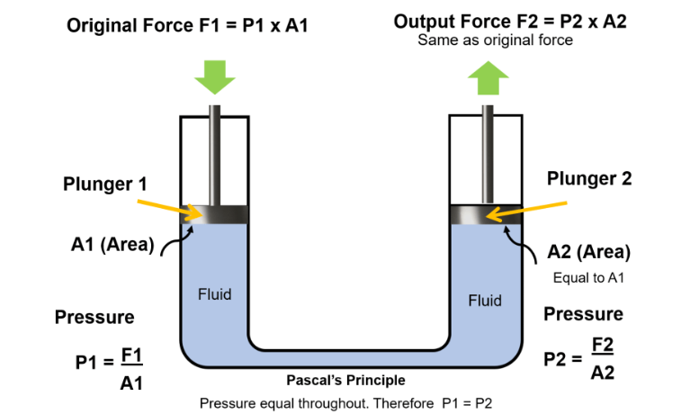
Pascal’s Law states that pressure applied to a confined incompressible fluid is transmitted equally in all directions throughout the fluid. French mathematician Blaise Pascal established this principle in 1653, and it remains the theoretical bedrock of every hydraulic system.
The mathematical expression is straightforward: P₁ = P₂, where pressure at any point equals pressure at every other point in a confined fluid. Since pressure equals force divided by area (P = F/A), this creates a powerful relationship:
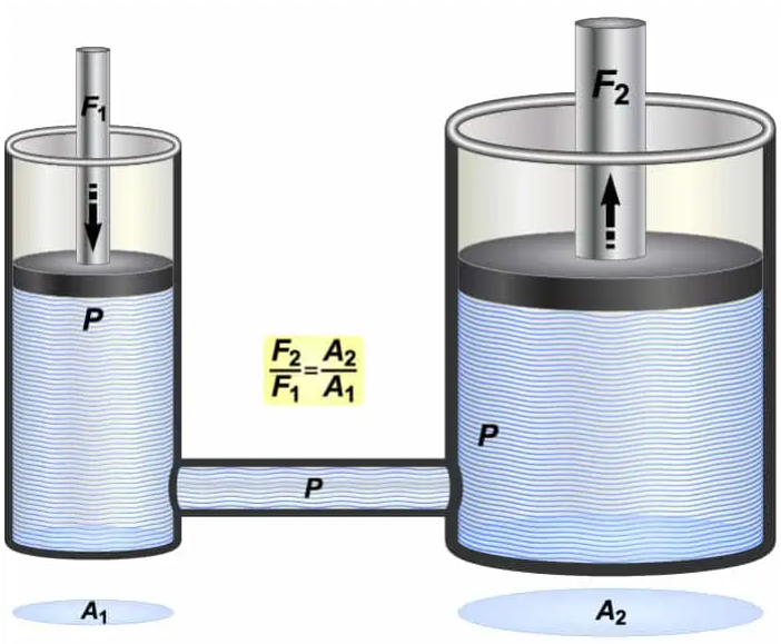
F₁/A₁ = F₂/A₂
This equation enables force amplification. A 10-pound force applied to a 1-square-inch piston creates 10 psi pressure throughout the system. That same 10 psi acting on a 10-square-inch piston generates 100 pounds of force—a tenfold increase with no additional energy input beyond the initial force.
The principle works because liquids, unlike gases, are virtually incompressible under normal operating conditions. When you apply force to one part of the fluid, the molecules can’t compress to absorb that force, so they transmit it instead. This property distinguishes hydraulic systems from pneumatic systems, which use compressible gases and exhibit different performance characteristics.
Real applications demonstrate this dramatically. In a hydraulic car jack, a small input cylinder with 1 square inch area connects to a lifting cylinder with 50 square inches. A mechanic applying 20 pounds of force generates 20 psi pressure. That pressure acts on the larger cylinder to produce 1,000 pounds of lifting force (20 psi × 50 sq in). The tradeoff appears in distance: the small piston must travel 50 inches to move the large piston 1 inch.
Modern excavators leverage this principle extensively. The operator’s control lever moves a small pilot piston, creating pressure that controls much larger main pistons in the boom and bucket cylinders. A construction operator can generate tens of thousands of pounds of digging force by moving a lever with just a few pounds of input.
The second principle centers on a liquid property: incompressibility. While technically possible to compress liquids, doing so requires enormous pressure and yields minimal volume reduction. For practical hydraulic work, liquids behave as incompressible substances.
This characteristic matters because it enables immediate and precise force transmission. When you push on one end of a hydraulic line, the force appears instantly at the other end. There’s no spongy delay as the fluid compresses before acting. In a hydraulic brake system, this means the instant you press the pedal, pressure reaches all four brake calipers simultaneously—no lag, no uncertainty.
Compare this to pneumatic systems using compressed air. Air compresses easily, creating delays and less precise control. Pneumatic tools work well for applications requiring speed and simplicity, but when you need precise positioning or holding power, hydraulics dominate. An aircraft landing gear uses hydraulics rather than pneumatics precisely because there’s zero tolerance for position uncertainty when extending or retracting gear.
The practical impact shows up in numbers. Hydraulic fluid might compress by 0.5% under 3,000 psi pressure. Air under the same pressure would compress by roughly 95% of its original volume. This vast difference explains why hydraulic presses can hold tons of pressure steadily on a workpiece, while pneumatic systems excel at high-speed repetitive actions where exact positioning matters less.
Incompressibility also creates challenges. Any air bubble trapped in hydraulic lines becomes a compressible pocket that absorbs force instead of transmitting it. This is why “bleeding” air from brake lines is critical maintenance—even a small air pocket makes brakes feel mushy and reduces stopping power. Hydraulic systems require careful assembly and regular maintenance to exclude air from the fluid circuits.
The third principle governs fluid movement through the system. The Continuity Equation states that in a closed hydraulic circuit, the flow rate remains constant throughout. Mathematically: A₁V₁ = A₂V₂, where A is the cross-sectional area and V is fluid velocity.
This means when fluid flows through a narrower section of pipe, it must speed up to maintain the same volume flow rate. When the pipe widens, velocity decreases. The product of area and velocity stays constant, assuming the fluid is incompressible and there are no leaks.
This principle directly affects hydraulic cylinder speed. If a pump delivers 5 gallons per minute (GPM) to a cylinder with a 2-inch bore (area of 3.14 square inches), the piston extends at a specific velocity. Connect that same pump to a cylinder with a 4-inch bore (12.56 square inches), and the piston moves four times slower because the same volume of fluid must fill a cross-section four times larger.
The implications shape system design. When you need high speed with light loads, you use smaller cylinders. For heavy loads at slower speeds, larger cylinders work better. Many mobile hydraulic systems use variable displacement pumps that adjust flow rate to match demand—delivering high flow for fast motion when loads are light, then reducing flow while increasing pressure for powerful slow movements.
Flow velocity also creates practical constraints. Fluid moving too quickly through pipes generates turbulence, heat, and pressure losses through friction. Industry standards recommend keeping fluid velocity under 20 feet per second in pressure lines and under 4 feet per second in suction lines to avoid cavitation and excessive heat. Proper pipe sizing balances these factors: too narrow creates friction losses, too wide wastes space and material.
The fourth foundational principle addresses energy within flowing fluids. Bernoulli’s Principle states that in a flowing fluid, the sum of potential energy (elevation), kinetic energy (motion), and pressure energy remains constant, assuming no energy losses to friction or heat.
The simplified equation: P + ½ρv² + ρgh = constant, where P is pressure, ρ is fluid density, v is velocity, g is gravitational acceleration, and h is height.
This principle explains pressure drops and energy conversions in hydraulic circuits. When fluid flows from a reservoir up to a cylinder elevated 10 feet above, some pressure energy converts to potential energy to lift the fluid. When fluid speeds through a restriction, pressure energy converts to kinetic energy. When fluid slows down in a larger chamber, kinetic energy converts back to pressure.
Understanding this helps troubleshoot problems. If a hydraulic cylinder at the top of a machine moves sluggishly, Bernoulli’s principle suggests checking whether the system has sufficient pressure to overcome the elevation difference. The pressure at the cylinder will be lower than at the pump by an amount equal to the fluid weight in the vertical column.
Flow control valves deliberately manipulate this principle. An orifice or flow control creates a restriction that forces fluid velocity to increase. According to Bernoulli’s principle, increased velocity means decreased pressure at that point. The pressure drop across the orifice can be measured and used to calculate flow rate, which is how flow meters work. Variable orifices (adjustable restrictors) control cylinder speed by managing how much fluid flows per unit time.
Heat generation in hydraulic systems also relates to Bernoulli’s principle and energy conservation. When fluid flows through tight restrictions, energy converts from pressure to kinetic energy and then to heat through turbulence and friction. Oversized pressure relief valves dumping flow continuously, or undersized lines creating excessive fluid velocity, both generate heat that must be removed through coolers. Efficient systems minimize these conversions by proper component sizing and pressure matching.
These four principles combine to create predictable force-pressure-area relationships that define hydraulic system behavior. The core equation F = P × A appears simple but enables powerful calculations.
Consider a hydraulic press. You want to generate 100,000 pounds of force (100 kips in engineering terms) on a metal stamping die. If your system operates at 3,000 psi, you can calculate the required cylinder bore area: A = F/P = 100,000 lbs / 3,000 psi = 33.33 square inches. That’s a cylinder with roughly a 6.5-inch bore diameter.
But force calculations aren’t always straightforward because most cylinders are double-acting—they push and pull. The rod takes up area on one side, creating an imbalance. A cylinder with a 4-inch bore and 2-inch rod has 12.57 square inches on the cap end (full piston area) but only 9.42 square inches on the rod end (piston area minus rod area). At 1,000 psi, it pushes with 12,570 pounds but pulls with only 9,420 pounds—a 25% difference. Engineers must account for this when designing systems requiring equal force in both directions.
Pressure ratings define system capabilities. Industrial mobile equipment commonly operates at 3,000-5,000 psi. Some construction equipment runs at 5,000-6,000 psi for maximum power density. Aircraft hydraulic systems operate at 3,000-5,000 psi, with some military aircraft using 8,000 psi. Higher pressure means smaller components for the same force, saving weight and space. However, higher pressure requires stronger materials, better seals, and more careful design to handle the stresses.
The pressure-flow-power triangle completes the picture. Hydraulic power (horsepower) equals pressure (psi) times flow (GPM) divided by 1,714. A system delivering 10 GPM at 2,000 psi transmits 11.7 horsepower. Understanding this relationship helps size pumps, motors, and reservoirs. A 25-horsepower electric motor driving a pump at 75% efficiency provides about 18.75 hydraulic horsepower, which could deliver 32 GPM at 1,000 psi or 16 GPM at 2,000 psi.
Hydraulic systems integrate several components, each serving specific functions based on the four core principles. Understanding how these parts work together reveals the elegance of hydraulic design.
The reservoir stores fluid, but it’s more than just a tank. It provides cooling surface area for heat dissipation. Contaminants settle out during fluid rest time. Air bubbles rise and escape. Proper reservoir design includes baffles separating the return and suction areas, preventing fluid from short-circuiting and ensuring adequate residence time for cooling and deaeration. The reservoir should hold 2-3 times the pump’s flow rate per minute to provide sufficient dwell time.
Pumps convert mechanical energy from an electric motor or engine into hydraulic energy by moving fluid. They don’t create pressure—they create flow. Pressure only develops when that flow meets resistance. A pump running freely with all valves open generates minimal pressure. Connect a load and close a valve, and pressure rises to whatever level is needed to move that load or open that valve. Relief valves protect pumps by limiting maximum pressure, dumping excess flow back to the tank when preset pressure is reached.
Gear pumps, vane pumps, and piston pumps each suit different applications. Gear pumps are simple and economical for pressures up to 3,000 psi. Vane pumps offer quieter operation and can be made variable displacement. Piston pumps handle the highest pressures (up to 10,000 psi) and efficiencies but cost more. Variable displacement piston pumps adjust their output to match demand, saving energy compared to fixed displacement pumps running continuously.
Valves control flow direction, pressure levels, and flow rates. Directional control valves route fluid to cylinder or motor ports, determining which way they move. Pressure control valves limit maximum system pressure (relief valves), reduce pressure to lower levels (reducing valves), or maintain backpressure (counterbalance valves). Flow control valves meter the rate of fluid delivery, directly controlling actuator speed.
Modern valves use proportional or servo control, where electrical signals modulate valve position for precise control. An operator’s joystick signal translates to valve opening percentage, which determines flow rate and thus cylinder or motor speed. This closed-loop control, combined with position sensors, enables excavators to follow complex dig patterns and cranes to place loads with millimeter precision.
Actuators convert hydraulic energy back to mechanical work. Cylinders produce linear motion—extend and retract. Motors produce rotary motion. Cylinder force calculations are straightforward using F = P × A. Motor torque calculations use T = (P × D) / (2π), where D is motor displacement in cubic inches per revolution. A motor with 5 cubic inch displacement running at 2,000 psi generates approximately 1,592 inch-pounds of torque.
Filters, coolers, and accumulators round out the system. Filters remove contaminants that would damage precision components—particles larger than 3-5 microns in servo systems. Heat exchangers maintain fluid temperature in the optimal range, typically 110-140°F. Accumulators store pressurized fluid, absorbing pressure shocks and providing auxiliary power during peak demand or pump failure.
Manufacturing relies heavily on hydraulic presses for metal forming, stamping, and molding. A 500-ton press generates 1,000,000 pounds of force to stamp automotive body panels from sheet steel. Multiple cylinders acting together create this force, with programmable control managing press speed, dwell time, and pressure. Modern servo-hydraulic presses combine hydraulic force capacity with electrical precision, enabling complex forming operations that would be impossible with mechanical presses.
Construction and mining equipment demonstrates hydraulics at its most powerful. An excavator’s boom cylinders must lift the boom structure, dipper stick, bucket, and maximum material load—perhaps 5 tons total—while extending 20 feet away from the machine pivot. The cylinder bore might be 6 inches with a 3.5-inch rod, operating at 5,000 psi, generating over 140,000 pounds of lifting force. The complex kinematics of the boom-stick-bucket linkage means the operator simply moves joysticks while the hydraulic system automatically coordinates three or four cylinders to achieve the desired bucket path.
Mobile cranes lifting 200+ tons rely on hydraulic telescoping booms. As the boom extends, built-in cylinders push sections outward, each locked into place mechanically. The main lift cylinders, with bores exceeding 12 inches, operate at 5,000+ psi to handle extreme loads. Computer controls monitor load weight, boom angle, and extension to prevent tipover. Multiple pumps driven by the chassis engine deliver combined flows exceeding 100 GPM during heavy lifts.
Aircraft depend on hydraulics for primary flight controls, landing gear, and braking. A Boeing 737’s rudder and elevator actuators use 3,000 psi hydraulics for control forces exceeding what pilots could generate manually. Redundant systems (often three independent hydraulic systems) ensure safety. The landing gear cylinders must not only lower and lock the gear but also withstand landing impact loads—a dramatic demonstration of hydraulic systems absorbing and managing extreme forces.
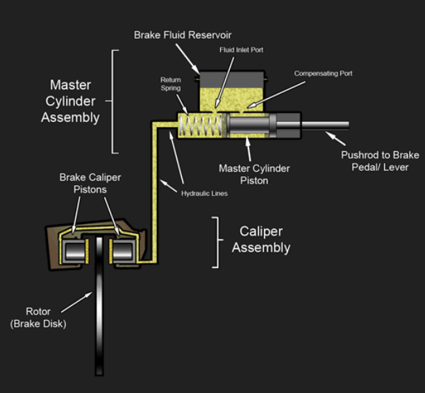
The automotive industry uses hydraulics in every brake system. Master cylinders convert pedal force into hydraulic pressure. Brake calipers at each wheel convert that pressure back into mechanical clamping force on rotors. A typical brake system operates at 1,000-1,500 psi during normal braking, potentially reaching 2,000 psi during hard stops. The pressure balance between front and rear brakes, managed by proportioning valves, prevents wheel lockup and optimizes stopping distance.
Power steering systems, whether hydraulic or electro-hydraulic, amplify driver input force. The steering pump (driven by the engine belt) generates pressure on demand. The steering gear contains a valve that directs pressurized fluid to assist the driver’s turning effort. Newer electro-hydraulic systems use an electric motor to drive a small hydraulic pump only when steering assist is needed, saving fuel compared to continuously-driven pumps.
Industrial automation uses hydraulics where high force and precise positioning intersect. Assembly line clamping fixtures must apply consistent, high clamping force to hold parts during welding or machining. Hydraulic cylinders deliver this force reliably. Injection molding machines use hydraulics to close molds (requiring hundreds of tons of clamp force), inject molten plastic at high pressure, and eject finished parts. A large injection molding machine might use a 1,000-ton hydraulic press for mold clamping while precisely controlling injection pressure and speed through servo-hydraulic valves.
Hydraulic systems face several recurring issues that stem from violations of the core principles or component wear. Air contamination creates the “spongy” response mentioned earlier. Since air is compressible, air bubbles in the fluid act as cushions that absorb force rather than transmitting it. The solution requires bleeding air from high points in the system and ensuring pump suction lines don’t introduce air through leaky connections.
Fluid contamination causes 70-80% of hydraulic system failures. Particles as small as 5 microns—invisible to the naked eye—can damage servo valve clearances measured in millionths of an inch. Wear particles from one component damage other components, creating an accelerating failure cascade. Proper filtration is essential. Offline filtration systems (sometimes called kidney loop filters) continuously clean fluid from the reservoir, maintaining contamination levels well below ISO 4406 standards. Return line filters catch particles generated by component wear before they enter the reservoir.
Temperature extremes harm performance and component life. Cold fluid increases viscosity, slowing system response and forcing pumps to work harder. Many cold-climate machines include reservoir heaters or recirculation systems to warm fluid before operation. Hot fluid decreases viscosity, increasing internal leakage past pump vanes and cylinder seals. Excessive heat (over 180°F) accelerates fluid oxidation and seal degradation. Heat exchangers sized to system horsepower maintain optimal operating temperatures.
Cavitation occurs when fluid pressure drops below the vapor pressure, forming bubbles that violently collapse when pressure recovers. This happens on pump suction lines that are undersized, kinked, or fitted with clogged filters. The symptom is a distinctive crackling noise. The damage includes pitting erosion on metal surfaces and rapid pump wear. Prevention requires properly sized suction lines (keeping velocity under 4 ft/sec), clean suction strainers, and adequate reservoir fluid level.
Seal leakage develops as seals wear from contamination, heat, or simply age. External leakage is visible and messy but relatively harmless beyond fluid loss. Internal leakage—fluid bypassing from high pressure to low pressure sides of a pump or cylinder—reduces system performance without obvious signs. A cylinder that once moved quickly under load now creeps slowly because worn piston seals allow fluid to leak past, reducing effective flow. Diagnostic testing measuring flow and pressure at various points identifies internal leakage sources.
Pressure is force per unit area, measured in pounds per square inch (psi) or pascals (Pa). Force is the total push or pull, measured in pounds or newtons. A hydraulic system at 1,000 psi generates 1,000 pounds of force on each square inch of piston area. A 10-square-inch piston at 1,000 psi produces 10,000 pounds of total force.
Oil provides lubrication for moving parts, has higher boiling points than water, doesn’t promote rust, and can be formulated with additives for specific performance characteristics. Water-based fluids exist for fire-resistant applications, but mineral oil remains standard because it combines incompressibility with excellent lubrication and reasonable cost.
Cold temperatures increase fluid viscosity, making the system sluggish or unable to operate. Special low-temperature hydraulic fluids maintain adequate viscosity at -40°F or below. Systems may include reservoir heaters or recirculation loops to warm fluid before operation. Arctic and military equipment uses specialized fluids and thermal management.
Hydraulic power equals pressure multiplied by flow rate, divided by a constant. The formula is HP = (PSI × GPM) / 1,714 in US units. A system delivering 10 GPM at 2,000 psi transmits 11.7 horsepower. This calculation helps size pumps, motors, and heat exchangers by quantifying energy flow through the system.
Hydraulic principles remain remarkably consistent across applications from miniature dental equipment to massive mining excavators. The elegance lies in how four simple physical principles—pressure transmission, incompressibility, flow conservation, and energy conservation—combine to enable force multiplication, precise control, and reliable power transmission through simple fluid-filled tubes and cylinders. Modern materials, electronics, and manufacturing improve component performance, but Pascal discovered the fundamental truth nearly four centuries ago: confined fluids transmit force with remarkable efficiency.