
A hydraulic system uses pressurized fluid to transfer energy and generate force for mechanical work. The system operates on Pascal’s Law, which states that pressure applied to a confined fluid transmits equally in all directions, allowing small input forces to create substantially larger output forces through strategic component sizing.
Pascal’s Law forms the theoretical foundation of every hydraulic system. When you apply pressure to an incompressible fluid confined within a closed container, that pressure distributes uniformly throughout the entire fluid volume. This principle, discovered by French mathematician Blaise Pascal in 1653, enables hydraulic systems to multiply force with remarkable efficiency.
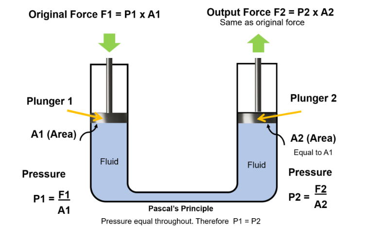
The mathematical relationship is straightforward: pressure equals force divided by area (P = F/A). In a hydraulic system with two pistons of different sizes connected by fluid, equal pressure means the larger piston experiences proportionally greater force. If a small piston with 1 square inch of area receives 100 pounds of force, it creates 100 psi throughout the system. A larger piston with 10 square inches at that same 100 psi pressure will generate 1,000 pounds of force.
Unlike air or other gases, hydraulic fluid is essentially incompressible. This characteristic is critical because it ensures pressure transmission remains immediate and consistent across the system, with minimal energy loss through fluid compression.
Every functional hydraulic system requires specific components working in coordinated sequence. Understanding these parts clarifies how hydraulic systems convert energy and perform work.
The pump serves as the system’s heart, converting mechanical energy from an electric motor or engine into hydraulic energy. Pumps create flow by generating a vacuum at the inlet, which forces fluid from the reservoir into the system. As the pump’s mechanical action pushes fluid toward the outlet, it builds pressure throughout the hydraulic circuit.
Three main pump types dominate industrial applications. Gear pumps use meshing gears to move fixed fluid volumes per rotation, offering simple, reliable operation at pressures up to 25 MPa. Vane pumps employ rotating vanes within a cam ring to create variable displacement, providing quieter operation. Piston pumps deliver the highest pressures and efficiencies, with some designs reaching 70 MPa for demanding applications.
Variable displacement pumps adjust their output to match system demand, improving energy efficiency compared to fixed displacement designs that move constant volumes regardless of need.
The hydraulic fluid itself is a component, not just a medium. Most systems use petroleum-based oil for its excellent lubrication properties and incompressibility. The fluid must maintain consistent viscosity across operating temperatures, resist oxidation, and provide corrosion protection for internal components.
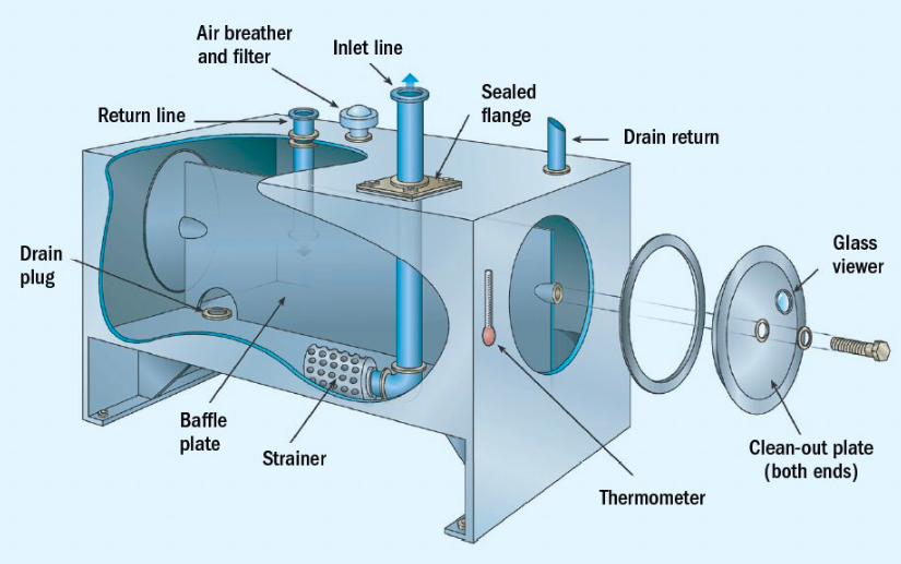
The reservoir stores fluid volume sufficient for system operation plus expansion allowances. Beyond simple storage, it facilitates air bubble separation, allows contaminant settling, and dissipates heat generated during operation. Proper reservoir sizing typically provides 3 to 5 times the pump’s per-minute flow rate.
Actuators convert hydraulic energy back to mechanical motion, performing the actual work. Hydraulic cylinders create linear motion through piston movement inside a barrel. Single-acting cylinders use hydraulic pressure for one direction of travel, relying on springs or gravity for return. Double-acting cylinders employ hydraulic force for both extension and retraction, offering greater control.
Hydraulic motors generate rotary motion by reversing the pump principle. Pressurized fluid entering the motor causes rotation of internal components, delivering torque to the output shaft. These motors power everything from winches and conveyors to vehicle wheels and industrial machinery.
Valves direct fluid flow, regulate pressure, and control actuator speed. Directional control valves determine which circuits receive pressurized fluid, enabling operators to select between multiple functions. Pressure relief valves protect the system by opening when pressure exceeds safe limits, returning excess fluid to the reservoir.
Flow control valves regulate the speed of actuators by restricting fluid flow rates. Proportional valves offer infinitely variable control between fully open and closed positions, enabling precise speed and force modulation that matches application requirements.
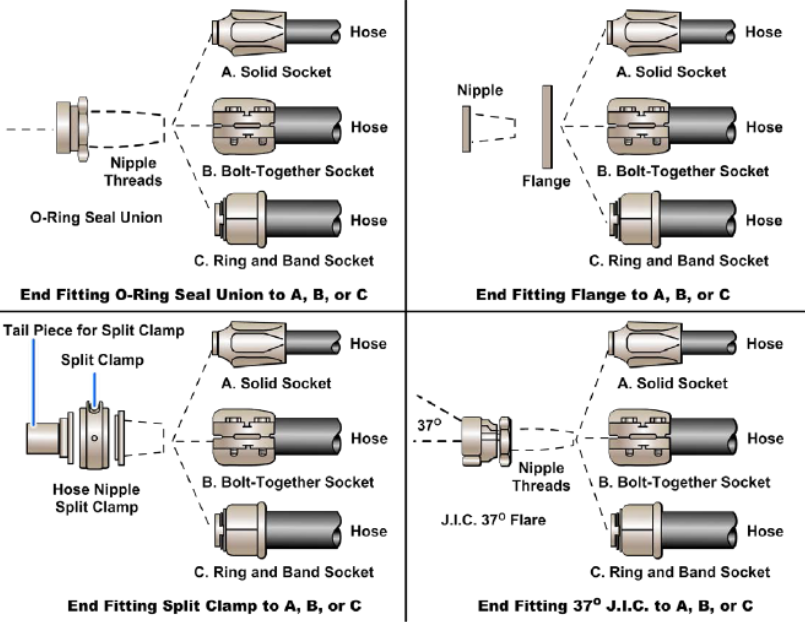
Steel tubes, flexible hoses, and specialized fittings create the pathways for fluid movement. Rigid steel lines handle high-pressure applications in fixed installations, while flexible hoses accommodate movement in mobile equipment. Every connection point requires proper fittings rated for system pressure, with seals preventing leakage.
The global hydraulics market reached $38.38 billion in 2024 and projects growth to $44.26 billion by 2030, reflecting widespread industrial adoption.
Operation begins when the operator activates the pump, typically through an electric motor or combustion engine. The pump draws fluid from the reservoir and delivers it under pressure into the system’s circuit. This pressurized fluid travels through lines to the control valves, which direct flow based on operator input or system programming.
When fluid reaches an actuator, pressure acts on piston surfaces or motor components, generating mechanical force. A hydraulic cylinder’s piston moves as pressurized fluid enters one side of the barrel, while fluid on the opposite side returns to the reservoir through the control valve. The force generated depends on pressure level and piston surface area exposed to that pressure.
Throughout this cycle, fluid continuously circulates. After performing work at the actuator, fluid returns to the reservoir at lower pressure. There it cools, releases trapped air, and allows contaminants to settle before the pump recirculates it. This closed-loop design prevents fluid loss while enabling continuous operation.
Filtration occurs at multiple points—suction filters protect the pump inlet, pressure filters clean fluid in the main circuit, and return filters capture particles before fluid re-enters the reservoir. Effective filtration is essential since contamination causes approximately 75% of hydraulic system failures.
Construction equipment represents the largest hydraulic application sector, accounting for roughly 19% of the market. Excavators, loaders, bulldozers, and cranes rely on hydraulic cylinders to lift loads exceeding 100 tons with precise control. A single excavator may contain 12 or more hydraulic cylinders controlling boom, stick, bucket, and track movements.
Agriculture equipment utilizes hydraulics for implement control and power transmission. Tractors employ hydraulic systems to raise and lower attachments, operate loaders, and control steering. The agriculture sector is experiencing the highest growth rate in hydraulic adoption as mechanization expands in emerging economies. India alone sold over 900,000 tractors in 2023, with most integrating hydraulic systems for multiple functions.
Manufacturing operations depend on hydraulic presses, injection molding machines, and automated production systems. Hydraulic presses generate forces exceeding 10,000 tons for metal forming, stamping, and compression molding. These machines offer precise force control and programmable operation sequences that mechanical systems cannot match.
Aerospace applications demand hydraulic systems for landing gear operation, flight control surfaces, and braking systems. Commercial aircraft use hydraulic pressure at 3,000 to 5,000 psi, with multiple redundant systems ensuring safety. The reliability requirements in aviation drive innovation in component design, materials, and monitoring systems.
Automotive systems incorporate hydraulics in power braking, power steering, and suspension components. A typical car’s brake system multiplies the driver’s foot pressure by ratios exceeding 10:1, converting modest pedal force into sufficient clamping force to stop a 4,000-pound vehicle from highway speeds.
Hydraulic systems deliver high force density, generating substantial power from compact components. A hydraulic cylinder occupying one cubic foot can easily produce forces exceeding 50,000 pounds. Achieving equivalent force with mechanical systems would require significantly larger, heavier components.
The system provides infinitely variable control over speed and force. By adjusting pressure and flow rates, operators achieve precise movements from barely perceptible creep to rapid transit. This controllability makes hydraulics ideal for applications requiring delicate manipulation of heavy loads.
Hydraulic fluid provides inherent lubrication for moving components, reducing wear and extending service life. The incompressible nature of hydraulic oil also enables systems to stop and hold loads at any position without continuous power input, unlike electric or pneumatic systems.
Overload protection is built-in through pressure relief valves. If a cylinder encounters an immovable obstruction, pressure simply rises until the relief valve opens, preventing component damage. Mechanical systems lack this automatic protection, risking breakage under overload conditions.
Energy storage through accumulators allows hydraulic systems to meet instantaneous peak demands exceeding pump capacity. The accumulator stores pressurized fluid during low-demand periods, then releases it rapidly when needed for quick actuator movements or emergency operations during power failures.
Traditional hydraulic systems operate at approximately 23% overall efficiency according to Oak Ridge National Laboratory assessments, indicating substantial energy waste. This inefficiency stems from throttling losses in control valves, fluid friction in lines, and heat generation throughout the circuit.
Modern electro-hydraulic systems address efficiency concerns by combining electric servo motors with hydraulic pumps, adjusting pump output to precisely match system demand. These systems eliminate the constant-pressure, variable-flow approach of traditional designs, reducing energy consumption by 30% to 50% in typical applications.
Variable displacement pumps contribute to efficiency by altering their displacement to match load requirements rather than running continuously at maximum capacity. Proportional controls refine this approach by enabling smooth transitions and eliminating the energy waste associated with on-off cycling.
Heat generation accompanies pressure drops and fluid friction, requiring cooling systems in high-power applications. Heat exchangers, cooling fins on reservoirs, and dedicated coolers maintain fluid temperatures within acceptable ranges. Biodegradable hydraulic fluids now available reduce environmental risks from inevitable leakage while maintaining necessary performance characteristics.
Effective hydraulic system design starts with calculating actual force and speed requirements, then adding appropriate safety margins. Undersized components operate at excessive pressures or velocities, accelerating wear and reducing reliability. Oversized components waste energy and increase initial costs without performance benefits.
Fluid velocity limits prevent cavitation, erosion, and excessive pressure drops. Suction lines should maintain velocities below 4 feet per second to prevent cavitation at the pump inlet. Pressure lines typically operate at 10 to 20 feet per second, while return lines function effectively at 5 to 10 feet per second.
Filtration strategy depends on component sensitivity and contamination sources. ISO cleanliness code standards specify acceptable particle counts by size range. Systems with servo valves or proportional controls require cleanliness levels of ISO 16/14/11 or better, while less sensitive equipment tolerates ISO 20/18/15.
Circuit design should minimize pressure drops, avoid sharp bends in lines, and position components for serviceability. Placing the reservoir below the pump improves suction conditions, while mounting filters in accessible locations facilitates maintenance. Pressure gauges at key points enable troubleshooting and performance monitoring.
Regular maintenance preserves hydraulic system performance and prevents costly failures. Fluid analysis detects early signs of component wear, contamination, and fluid degradation. Testing for viscosity, particle counts, water content, and wear metals provides insights into system health before problems cause downtime.
Filter replacement follows manufacturer intervals or when differential pressure indicators signal restriction. Waiting until complete filter bypass occurs allows contaminants to circulate freely, causing accelerated wear throughout the system. Most maintenance programs replace filters at 500 to 2,000 operating hours depending on contamination levels.
Seal replacement prevents leakage that wastes fluid, contaminates the environment, and reduces system pressure. O-rings, rod seals, and piston seals degrade from pressure cycles, temperature extremes, and fluid compatibility issues. Systematic seal replacement during scheduled maintenance prevents emergency repairs and production disruptions.
Fluid changes maintain proper viscosity, additive levels, and cleanliness. While high-quality hydraulic oils can last 5,000 hours or longer in controlled environments, systems operating in harsh conditions require more frequent changes. Oil analysis guides change intervals based on actual condition rather than arbitrary schedules.
Hydraulic systems store significant energy in pressurized fluid, creating serious hazards if released unexpectedly. A pinhole leak in a 3,000 psi system generates a fluid jet capable of penetrating skin and causing injection injuries requiring immediate medical intervention. These injuries often lead to amputation if not treated within hours.
Proper lockout/tagout procedures are mandatory before performing maintenance. Simply shutting off the pump leaves residual pressure in the system. Technicians must relieve all pressure by cycling actuators, opening bleed valves, and verifying zero pressure on gauges before disconnecting any components.
Hydraulic fluid under pressure can ignite if it contacts hot surfaces above its flash point, typically 400°F to 600°F for petroleum oils. Leaks near exhaust manifolds, turbochargers, or other heat sources create fire risks. Routine leak inspections and prompt repairs minimize these hazards.
Component failure modes include burst hoses, blown seals, and ruptured cylinders. Proper component selection based on working pressure ratings, including adequate safety factors, prevents catastrophic failures. Most hydraulic components are rated for working pressures at 2:1 or 3:1 safety factors relative to burst pressure.
Smart hydraulic systems integrate sensors throughout the circuit, monitoring pressure, temperature, flow rates, and fluid condition in real time. Internet of Things connectivity enables remote monitoring, predictive maintenance scheduling, and performance optimization through data analytics. These systems detect developing problems weeks before they cause failures, reducing unplanned downtime.
Hybrid systems combine hydraulic power with electric actuators, capturing regenerative energy during load lowering or deceleration. In mobile equipment, this recovered energy charges batteries or supercapacitors, reducing overall fuel consumption by 10% to 30% in typical duty cycles.
Miniaturization advances enable powerful hydraulic components in increasingly compact packages. High-strength alloys and advanced manufacturing techniques allow smaller cylinders and motors to handle pressures exceeding 40 MPa while weighing substantially less than conventional designs.
Integration with artificial intelligence and machine learning algorithms optimizes system performance based on operating patterns. These adaptive systems automatically adjust pressure levels, flow rates, and control characteristics to minimize energy consumption while maximizing productivity.
Hydraulic systems use incompressible liquid (typically oil), while pneumatic systems use compressible air. This fundamental difference means hydraulics can generate much higher forces and hold loads precisely at any position. Pneumatics suit lighter-duty applications requiring rapid movements with less force, as compressed air stores energy differently and exhibits spring-like behavior under load.
Hydraulic oil provides essential lubrication for moving components, preventing wear in pumps, valves, and actuators. Oil also resists corrosion, functions across broader temperature ranges, and remains stable for extended periods. Water causes rust, freezes at 32°F, and lacks lubricating properties, though water-based fluids are used in specific applications requiring fire resistance.
Industrial hydraulic systems commonly operate between 1,000 and 3,000 psi. Mobile equipment like construction machinery uses 3,000 to 5,000 psi, while specialized applications reach 10,000 psi or higher. System pressure depends on force requirements, with higher pressures enabling smaller components for equivalent force output.
Contamination accounts for approximately 75% of hydraulic failures. Dirt particles, water, and wear debris damage close-tolerance components like pumps and valves. Other common failure modes include improper fluid selection, inadequate maintenance, overheating, and excessive vibration. Proper filtration and regular fluid analysis prevent most contamination-related problems.
Hydraulic systems convert pressurized fluid into controlled mechanical force through interconnected components operating on established physical principles. Their ability to generate high forces from compact packages, combined with precise control characteristics, explains their continued dominance in heavy equipment, manufacturing, and mobile machinery despite ongoing electrification trends in lighter applications.
The technology’s fundamentals—incompressible fluid, pressure multiplication through area differences, and closed-loop circulation—remain unchanged since Pascal’s era. Modern advances focus on efficiency improvements, electronic integration, and intelligent monitoring rather than altering basic operating principles. This stability means hydraulic systems will continue serving applications requiring substantial force and robust performance in demanding environments.