
Hydraulic valves control fluid flow, direction, and pressure within hydraulic systems through mechanical elements like spools or poppets. These components are essential in pressure regulation, where they maintain safe operating ranges, prevent equipment damage, and ensure consistent performance across varying load conditions.
Pressure regulation in hydraulic systems relies on valves to manage three critical parameters: maximum pressure limits, downstream pressure levels, and sequential pressure operations. Each function addresses specific operational needs while protecting system components from mechanical stress and premature failure.
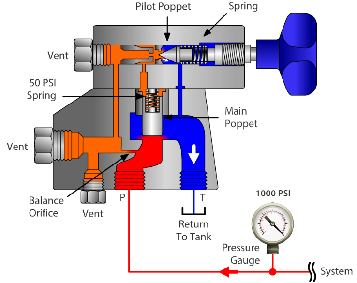
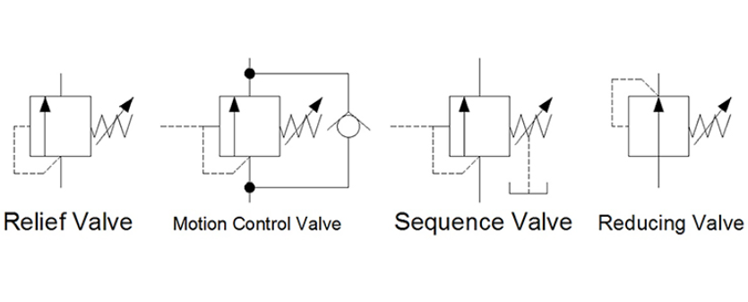
Relief valves prevent system overpressure by diverting excess fluid when pressure exceeds preset thresholds. Research indicates these valves are installed in virtually every fixed-volume hydraulic circuit, where they function as primary safety devices. When system pressure reaches approximately 90% of the maximum rating, pilot-operated relief valves begin opening gradually, maintaining system efficiency by minimizing unnecessary fluid bypass. The cracking pressure—the point at which the valve first opens—differs from full-flow pressure, where the valve handles its maximum rated flow. This graduated response protects components while preventing sudden pressure drops that could disrupt operations.
Pressure-reducing valves serve a different purpose by maintaining lower pressure in secondary circuits regardless of main system fluctuations. These normally-open, two-way valves close when downstream pressure exceeds their setting. In direct-acting designs, a fixed pressure differential is maintained through spring force acting on equal pressurized areas. For instance, a valve set for 250 psi reduction will maintain that differential whether main pressure is 2,000 psi or 2,750 psi. Pilot-operated variants use downstream pressure feedback at both spool ends, with a built-in pilot relief valve that opens only when secondary pressure reaches its setpoint, providing more precise control for systems with variable loads.
Sequence valves enable ordered operations in multi-actuator systems. These normally-closed, two-way valves open only when upstream pressure reaches a predetermined level, directing flow to secondary actuators in proper sequence. A clamping cylinder might need to secure a workpiece before a drilling cylinder activates—sequence valves ensure this timing without electronic controls. The valve’s spring-biased spool monitors inlet pressure through a pilot passage, shifting position once the threshold is met.
Different hydraulic applications require specialized valve designs. Market data from 2024 shows the global hydraulic valve sector reached $5.94 billion, with pressure control valves representing a significant portion across construction, mining, and manufacturing industries.
Counterbalance valves address a unique challenge in vertical load applications. When a hydraulic cylinder supports weight—such as a crane boom or excavator arm—gravity can cause uncontrolled descent if system pressure drops. Counterbalance valves maintain preset backpressure in the return line, creating resistance equal to the load force. This prevents overrunning where the load would pull fluid through the circuit faster than the pump supplies it. The valve balances hydraulic force against spring force, opening in response to controlled pressure inputs while blocking reverse flow.
Unloading valves differ from relief valves by completely diverting pump output to the reservoir at low pressure when system demand ceases. These valves feature an inlet port, tank port, pilot port, and spring-biased spool. During normal operation, the spring holds the valve closed. When an external pilot signal—typically from a loaded circuit—reaches sufficient pressure, the spool shifts, redirecting full pump flow to tank at minimal pressure. This prevents heat buildup and energy waste during idle periods, extending component life and reducing power consumption. Two-pump hi-lo circuits commonly use unloading valves, where a small high-pressure pump handles precision work while a large low-pressure pump provides rapid movement.
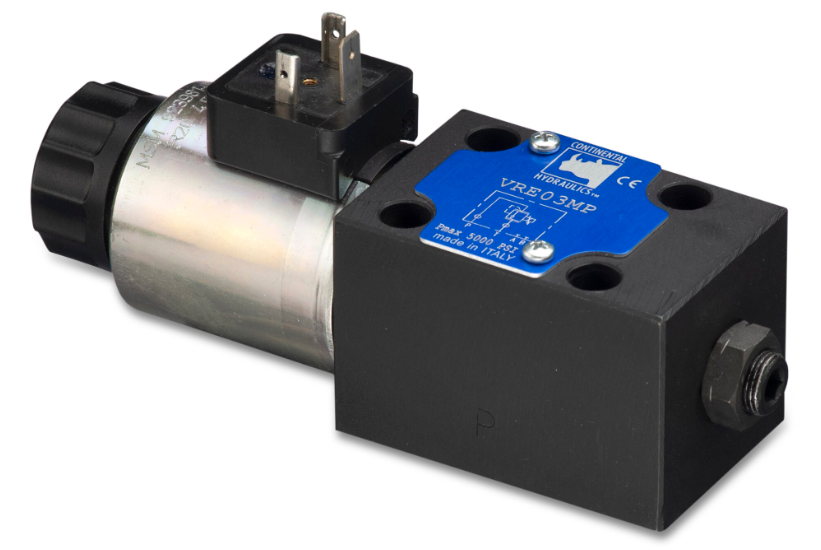
Proportional valves provide variable pressure and flow control rather than simple on-off operation. These electrically operated valves adjust their opening in proportion to input signals, typically 0-10V or 4-20mA. This enables precise speed control in applications requiring graduated motion, such as robotic arms or CNC machinery. The valve’s restrictor allows any number of spool positions, translating to infinitely variable flow rates within the valve’s range. Modern designs integrate position sensors and microprocessors for closed-loop control, automatically compensating for pressure variations.
Load-sensing technology represents a significant efficiency improvement over fixed-displacement systems. Traditional gear-pump circuits maintain constant flow regardless of demand, requiring relief valves to bypass excess fluid—generating heat and wasting energy. Load-sensing systems measure pressure downstream of directional control valves, adjusting pump output to match actual requirements plus a preset margin across the valve spool.
This approach maintains constant flow for any valve opening regardless of load or pump speed. Studies from mining equipment manufacturers show load-sensing systems reduce horsepower requirements by approximately 18.8 hp compared to conventional gear pumps. In one documented case, average power consumption dropped from 29.5 hp to 10.7 hp, significantly decreasing fuel consumption. The technology proves particularly valuable where engine horsepower is limited or when multiple actuators share a single pump, as it optimizes power distribution based on real-time demand.
Pressure-compensated flow control valves maintain consistent flow rates despite system pressure changes. These valves incorporate an adjustable orifice and a pressure-compensating element, typically a spring-loaded spool that monitors pressure differential. As system pressure fluctuates, the compensator adjusts the orifice size to maintain steady flow. This ensures actuator speed remains constant under varying loads—a crane boom won’t suddenly accelerate when the load lightens or slow when tension increases. The stability is critical for precision operations and operator safety.
Hydraulic pressure regulation requires careful valve selection and placement. Relief valves mount as close as practical to pumps or high-pressure zones, providing immediate response to pressure spikes. Direct-acting relief valves suit small to medium flows up to approximately 60 liters per minute, offering fast response but with higher pressure override—the difference between cracking pressure and full-flow pressure. Pilot-operated designs handle larger flows with minimal pressure override, maintaining more consistent regulated pressure though with slightly slower response times.
Pressure-reducing valves typically install between high-pressure primary circuits and lower-pressure secondary circuits. The valve must account for potential backflow; if the load in a secondary circuit generates pressure exceeding the valve setting, the valve closes to prevent reverse flow into the primary circuit. This prevents pressure buildup that could damage secondary components. External drain lines are essential for pilot-operated designs, routing leakage and control oil back to the reservoir to prevent pressure buildup in spring chambers.
Valve sizing significantly impacts system performance. Undersized valves create excessive pressure drop, generating heat and reducing efficiency. Oversized valves may not regulate properly at low flows, leading to instability. Flow capacity ratings specify maximum flow at acceptable pressure drop, typically measured in liters per minute or gallons per minute. Engineers must consider not just maximum system flow but also valve response characteristics—how quickly the valve reacts to pressure changes and whether that response time matches system dynamics.
Construction equipment relies heavily on pressure regulation for safe, precise operation. Excavators use multiple pressure control valves to manage boom, stick, and bucket movements independently. Each actuator may require different pressure levels—the bucket curl function needs higher pressure for breakout force, while boom swing requires lower pressure for smooth control. Pressure-reducing valves create these distinct pressure zones from a single pump source. Load-sensing systems prevent boom drop when operators release controls, maintaining hydraulic pressure until mechanical locks engage.
Mining operations present extreme demands for hydraulic pressure control. Equipment operates continuously in harsh environments with temperature extremes, contamination, and shock loads. Customized pressure control valves feature hardened spools, pressure-compensating elements, and load-sensing capabilities. Spool metering—precise machining of valve spool notches—controls fluid flow with accuracy that gives operators predictable, responsive feel. In deep mining where conventional equipment risks failure from temperature and pressure extremes, specialized high-pressure valves rated for 10,150 psi enable compact, reliable operation.
Manufacturing automation requires repeatable precision. Hydraulic presses use pressure control valves to regulate forming force, ensuring consistent part quality. Too much pressure damages tooling and workpieces; too little results in incomplete forming. Proportional pressure control valves interface with PLCs, adjusting pressure based on material type, thickness, and forming stage. The valves respond to sensor feedback, automatically compensating for oil temperature changes that affect viscosity and pressure response.
Proper pressure regulation extends component life while preventing catastrophic failures. Relief valves typically last 30 years with appropriate maintenance, but several failure modes require monitoring. Valve sticking occurs when contaminant buildup prevents smooth spool movement, causing pressure to exceed setpoints before the valve opens. Leakage past seals allows gradual pressure rise even with the valve nominally closed. These conditions manifest as systems not reaching designed pressure or exceeding maximum pressure limits.
Regular pressure testing verifies valve settings remain within specifications. Testing requires applying typical loads while monitoring gauge readings. Pressure should stabilize at the valve’s set point plus expected override. Significant deviation indicates adjustment needs or component wear. Adjustment procedures vary by design—some valves use spring tension adjustment screws that turn clockwise to increase pressure, while others employ shim stacks or pilot valve settings.
System contamination poses particular risk to pressure control valves. The close clearances between spools and bores—often just a few micrometers—trap particles that score surfaces and disrupt sealing. This wear on balance ends allows control pressure to leak, requiring higher line pressure to counteract spring force. Wear between pressure and exhaust passages causes fluid to bypass directly to tank, reducing overall system pressure. Filtration with 10-micrometer absolute rating helps protect these precision components, though filters themselves require monitoring to prevent restriction as they accumulate contaminants.
The hydraulic valve market shows steady growth driven by automation and efficiency requirements. Global market value reached $8.83 billion in 2024, with projections indicating growth to approximately $16.82 billion by 2035 at a 6.06% compound annual growth rate. This expansion reflects increasing demand for smart hydraulic valves integrating IoT capabilities for real-time monitoring and predictive maintenance.
Advanced valve designs incorporate pressure sensors, data analytics, and communication features. These smart valves transmit operating data to central systems, enabling condition-based maintenance rather than fixed schedules. Pressure trend analysis can predict seal wear, spring fatigue, or contamination before failures occur. Remote adjustment capability allows engineers to optimize pressure settings based on operating conditions without physical access to valves.
Electric control systems are gaining market share, representing approximately 35% of hydraulic valves in 2024. These electro-hydraulic valves combine mechanical reliability with electronic precision, offering faster response times and integration with digital control systems. Recent product launches by manufacturers like Bosch Rexroth and Parker Hannifin achieved approximately 25% improvements in operational efficiency while reducing downtime by nearly 20% through IoT integration.
Energy efficiency drives design innovation. Pressure-compensated valves with improved load-sensing reduce energy consumption by directing flow and pressure only where needed. This minimizes heat buildup—a safety benefit that also extends component life. Compact designs using advanced materials achieve the same pressure ratings in smaller packages, enabling more flexible equipment layouts. Carbon-fiber reinforced plastic cylinders, for instance, weigh only 35% as much as steel equivalents while handling working pressures above 10,000 psi.
Pressure relief valves protect systems by opening when pressure exceeds safe limits, diverting excess fluid to tank. They remain closed during normal operation. Pressure reducing valves maintain lower, constant pressure in secondary circuits by restricting flow. They operate normally open and close only when downstream pressure exceeds settings.
Different circuits within a system require different pressure levels for optimal performance. A single pump supplies fluid, but various actuators need specific pressures based on their loads. Relief valves protect against overpressure, reducing valves create secondary pressure zones, and sequence valves control operation order—all working together for safe, efficient operation.
Testing frequency depends on operating conditions and duty cycles. Critical safety applications require quarterly testing. Standard industrial systems typically test annually or after 2,000 operating hours. Heavy-duty or contaminated environments need more frequent inspection. Any time system performance changes—unexpected pressure readings, slow actuators, or unusual heat—warrants immediate valve testing.
Improperly adjusted or malfunctioning pressure control valves are common overheating causes. Relief valves set too low constantly bypass fluid, converting hydraulic energy to heat. Undersized valves create excessive pressure drop with similar heating effects. Sticking valves that fail to open properly cause pressure buildup and subsequent heat generation when fluid eventually bypasses. Proper sizing, adjustment, and maintenance prevent these issues.
Sources Referenced: