
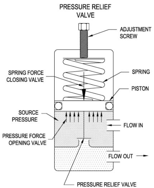
A hydraulic pressure relief valve protects systems by opening when fluid pressure exceeds a preset limit, automatically diverting excess flow to the reservoir. This spring-loaded mechanism maintains system pressure within safe operating ranges by balancing hydraulic force against adjustable spring tension.
The valve operates through a simple yet effective principle: when system pressure rises to the spring setting, hydraulic force overcomes spring resistance, causing the valve element to lift and create a flow path to tank.
The fundamental function of a hydraulic relief valve relies on force equilibrium between system pressure and mechanical spring resistance. Every relief valve contains three essential elements working in concert: a valve element (poppet or spool), a spring that determines the pressure setpoint, and a housing that directs fluid flow.
When system pressure acts on the valve element’s surface area, it generates an upward force. The spring applies an opposing downward force. As long as spring force exceeds hydraulic force, the valve remains sealed. Once pressure reaches the cracking point, typically 90-95% of the full relief setting, the valve begins to open incrementally.
The opening process creates a controlled restriction that bleeds excess pressure while maintaining downstream system pressure near the setpoint. Higher quality hydraulic safety relief valves demonstrate lower hysteresis—the difference between opening and closing pressures—which indicates more stable pressure control and better construction.
Direct measurement studies show that response times vary significantly between valve types. Direct-acting designs respond within 5-10 milliseconds, while pilot-operated configurations typically require 100 milliseconds due to the time needed for the pilot stage to actuate the main spool.
Direct-acting relief valves represent the simpler of the two main design categories found in hydraulic valves systems. These valves position the valve element—usually a poppet or spool—directly in the flow path, with system pressure acting immediately against the spring.
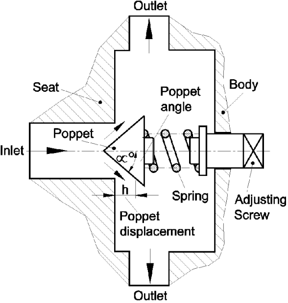
The poppet design features a disc or cone that seats against a precisely machined surface. Spring force holds this poppet firmly against its seat during normal operation. When inlet pressure generates sufficient force on the poppet’s exposed area, it lifts off the seat, creating a gap for fluid to escape to tank.
Spool-type direct-acting valves use a cylindrical element with metering grooves. While spool designs permit slightly higher leakage than poppets, they offer superior flow characteristics and smoother pressure regulation as the valve opens progressively.
One critical aspect of direct-acting valve performance is pressure override—the pressure increase from crack pressure to full flow. Depending on valve size and flow capacity, this delta can reach 500 PSI. For applications requiring operation near maximum system pressure, this characteristic makes direct-acting valves less suitable than pilot-operated alternatives.
The advantage of direct-acting designs lies in their rapid response to pressure transients. These hydraulic relief valves excel in applications with pressure-compensated pumps where quick spike suppression matters more than maintaining tight pressure regulation during continuous operation.
Pilot-operated pressure relief valves employ a two-stage design that dramatically improves pressure regulation characteristics compared to direct-acting types. The system consists of a small direct-acting pilot valve controlling a larger main stage poppet or spool.
The pilot stage monitors system pressure through a small orifice. This compact direct-acting valve, typically rated for flows under 5 GPM, sets the actual system relief pressure. The main stage, which handles full system flow, remains hydraulically balanced until the pilot valve opens.
When system pressure reaches the pilot setting, the pilot valve cracks open and drains fluid from the spring chamber of the main stage. This creates a pressure differential across the main spool or piston. Even a small pressure drop of 50-100 PSI across the main stage generates sufficient force to fully open the valve due to the large surface area involved.
This balanced design delivers two significant advantages. First, the pressure rise from crack to full flow typically spans only 50-100 PSI regardless of flow rate—far better than the 500 PSI delta common in direct-acting valves. Second, the pilot valve requires much less adjustment force than directly compressing a heavy main spring, enabling more precise pressure settings.
Applications with flow rates exceeding 60 liters per minute generally benefit from pilot-operated hydraulic relief valves. These valves maintain remarkably consistent system pressure even as flow varies, though their slower response time makes them less suitable for pressure spike suppression.
Understanding how a pressure relief valve hydraulic system maintains control requires examining the force equilibrium that governs valve operation. The relationship between fluid pressure, effective area, and spring force determines precisely when and how far the valve opens.
The hydraulic force acting to open the valve equals system pressure multiplied by the valve element’s exposed area. Spring force follows Hooke’s Law: force equals the spring constant multiplied by compression distance. At the cracking pressure point, these forces achieve equilibrium.
As system pressure climbs above crack pressure, hydraulic force exceeds spring force by an increasing margin. This force imbalance pushes the valve element farther off its seat. The opening increases proportionally until the flow area through the valve becomes large enough to pass all excess pump flow at the relief setting.
Most relief valves incorporate a damping orifice in the spring chamber. This small restriction introduces viscous resistance that dampens oscillations and prevents valve chatter—a high-frequency vibration that can damage components and create excessive noise. Without proper damping, the valve element can oscillate rapidly as it hunts between open and closed positions.
Temperature affects spring characteristics, and consequently relief pressure settings. A 50°C temperature increase can shift relief pressure by 3-5% in standard spring materials. Applications with wide temperature swings may require periodic adjustment or special high-temperature spring alloys to maintain consistent relief pressure.
Three distinct pressure values characterize relief valve performance: cracking pressure, full flow pressure, and reseat pressure. Each plays a specific role in system operation and protection.
Cracking pressure marks the point where the valve first begins to pass fluid—typically the first measurable drop flowing to tank. For direct-acting valves, this occurs at approximately 85-90% of the adjusted relief setting. Pilot-operated designs demonstrate tighter control, with cracking pressure reaching 90-95% of the setting.
Full flow pressure represents the pressure required to pass the valve’s rated flow capacity entirely to tank. The difference between crack and full flow pressure—the pressure override—directly impacts system efficiency. A hydraulic pressure relief valve with 200 PSI override operating near its setting wastes significant power as it partially opens and closes.
Reseat pressure, always lower than cracking pressure, indicates when the valve fully closes after being open. This hysteresis results from friction, spring characteristics, and valve geometry. High-quality valves exhibit reseat pressures within 5-10% of crack pressure, while lower-quality designs may show 15-20% differentials that cause erratic system behavior.
The global pressure relief valve market, valued at $4.7 billion in 2024, continues growing at 4.6% annually through 2034, driven primarily by stringent industrial safety requirements and infrastructure modernization across manufacturing, petrochemical, and power generation sectors.
The internal flow passages within a pressure release valve hydraulic system significantly influence performance characteristics including pressure drop, flow capacity, and noise generation. Engineers carefully design these passages to minimize turbulence while maximizing flow efficiency.
As the valve element lifts, it creates an annular gap between the element and its seat. Flow accelerates through this restriction, converting pressure energy into kinetic energy. Downstream of the restriction, the flow expands into a larger chamber where velocity decreases and some kinetic energy converts back to pressure—though never fully recovering to inlet levels.
Sharp edges and abrupt direction changes create turbulence that dissipates energy as heat and generates noise. Premium valve designs incorporate radiused edges and gradual transitions that promote smoother flow patterns. These refinements reduce the characteristic high-pitched squeal that direct-acting reliefs produce when passing flow at high pressure.
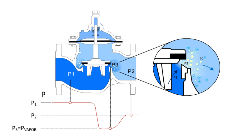
Cavitation presents a concern in high-pressure applications. When fluid velocity through the restriction causes local pressure to drop below vapor pressure, bubbles form and immediately collapse as flow enters the lower-velocity downstream region. This violent collapse erodes metal surfaces and creates damaging pressure waves. Proper valve sizing and staging help prevent cavitation damage.
For systems requiring flow capacities above 150-200 gallons per minute, cartridge-style relief valves offer advantages. These compact designs install into manifolds and can handle flows exceeding 600 GPM in single-stage configurations while maintaining tight pressure control.
Adjusting a hydraulic relief valve symbol properly requires understanding the relationship between spring compression and relief pressure. All relief valves incorporate an adjustment mechanism—typically a threaded screw that compresses or relaxes the spring.
The adjustment procedure begins with the system completely depressurized and the relief valve backed off to its minimum setting. After connecting a calibrated pressure gauge at the pump outlet, the operator starts the system and gradually increases the adjustment screw while monitoring gauge pressure.
Turning the adjustment clockwise compresses the spring, increasing the force required to open the valve and raising the relief pressure. Each full turn of the adjustment typically changes pressure by 100-300 PSI depending on spring rate and thread pitch. Fine adjustments require only partial turns to achieve the target pressure.
Once the desired pressure appears on the gauge, the operator tightens the locknut without disturbing the adjustment screw position. This locknut prevents vibration from changing the setting during operation. After securing the locknut, a final pressure check confirms the setting remained stable during locknut tightening.
Applications requiring frequent pressure changes benefit from remote adjustment capabilities available on pilot-operated valves. An external adjustment mechanism connects via tubing to the pilot section, allowing operators to modify system pressure from a convenient location rather than accessing the main valve body mounted near the pump.
The primary role of any relief valve in hydraulic systems extends beyond simple overpressure protection. These valves serve as the fundamental safety device that prevents catastrophic failure when actuators stall, directional valves malfunction, or excessive loads appear unexpectedly.
Consider a hydraulic press where a directional valve positions to extend the cylinder against a workpiece. As the ram contacts and compresses the material, resistance increases. Without a relief valve, pressure would climb rapidly as the pump continues delivering flow with nowhere to go. System pressure would rise until something fails—potentially a hose, cylinder seal, or even the pump housing.
The relief valve prevents this scenario by opening at its set pressure and providing a flow path to tank. The system maintains the relief pressure—generating the maximum available force at the cylinder—without exceeding safe limits. Heat generation becomes a concern if the valve remains open continuously, as all pump power converts to heat rather than useful work.
Well-designed systems rarely operate relief valves during normal cycles. The valve exists as a backup safety device, not a working component. Systems requiring regular pressure relief should instead use pressure-compensated pumps that reduce flow when pressure reaches the setting, or accumulator circuits that absorb pressure spikes without wasting energy.
Relief valves can last 30 years or more with proper maintenance and appropriate application. Failures typically result from contamination, excessive temperatures from continuous operation, or incorrect sizing that causes velocities exceeding component limits.
The hydraulic relief valve symbol follows ISO 1219-1:2012 standards that enable universal understanding across language barriers. This standardized symbolic representation conveys valve function, control method, and configuration through simple geometric shapes.
The basic relief valve symbol consists of a square containing a spring symbol and an arrow. The spring indicates mechanical force opposing hydraulic pressure. The arrow shows the direction of flow when the valve opens—from the inlet port to the outlet returning to tank.
A direct-acting relief valve symbol appears as a square with the spring and arrow positioned to show direct opposition. The hydraulic symbol for pressure relief valve of the pilot-operated type shows two connected squares: a small pilot section connected via a dashed pilot line to the larger main stage. This configuration immediately communicates the two-stage operating principle to anyone reading the schematic.
The symbols include adjustability indicators when applicable. A diagonal arrow through the spring denotes external adjustment capability. Pressure gauges, test points, and drain connections appear using their own standardized symbols at the appropriate ports.
Schematics following ISO standards enable maintenance technicians worldwide to quickly understand system function without requiring the original equipment documentation. The pressure relief valve hydraulic symbol location on the schematic typically appears immediately downstream of the pump, reflecting the actual installation position that provides most direct pressure protection.
Selecting the appropriate relief valve for a hydraulic system requires evaluating multiple factors including flow capacity, pressure range, response time requirements, and operating environment. Undersizing a valve causes excessive pressure override that may damage components despite the valve’s presence.
Flow capacity represents the most critical selection parameter. The valve must handle full pump flow at or near its rated pressure setting. A valve too small for the system flow rate requires excessive pressure rise to pass full flow, potentially doubling the pressure override specification and negating the protection the valve should provide.
Pressure range matching ensures the valve operates within its design envelope. Relief valves specify both minimum and maximum pressure ratings. Operating below minimum pressure causes poor control and excessive leakage. Exceeding maximum pressure risks mechanical failure of springs or valve elements.
Direct-acting valves suit applications under 60 liters per minute where rapid response matters more than tight pressure control. These include circuits with pressure-compensated pumps prone to pressure spikes, or test stands where quick pressure limiting prevents equipment damage during setup.
Pilot-operated hydraulic relief valves better serve high-flow systems requiring stable operating pressure near the maximum rating. Manufacturing equipment, mobile hydraulics in construction machinery, and industrial presses typically employ pilot-operated designs. The oil and gas sector, representing a $72.6 billion market by 2033, extensively uses these valves for pipeline pressure regulation and wellhead protection.
Relief valve problems manifest through several distinct symptoms, each pointing to specific failure mechanisms. Recognizing these patterns enables quick diagnosis and appropriate corrective action.
A system failing to build pressure often indicates a relief valve opening prematurely. This occurs when the adjustment backs off due to vibration loosening the locknut, the spring breaks or loses tension, or contamination prevents the valve element from seating properly. Verification requires measuring actual relief pressure and comparing it to the intended setting.
Conversely, pressure exceeding the relief setting suggests the valve is stuck closed. Contamination lodged between the element and its seat, internal corrosion from moisture or chemical incompatibility, or spring misalignment can prevent opening. In severe cases, the element may be frozen in place, requiring valve replacement.
Valve chatter—a rapid vibration producing high-pitched noise—results from insufficient damping, worn valve elements, or operating too close to crack pressure where the valve hunts between open and closed. Increasing the relief setting by 10-15% above normal operating pressure often eliminates chatter in marginally sized valves.
Continuous leakage past a closed relief valve signals seal degradation, element erosion from contamination, or cavitation damage. Small amounts of leakage are normal in spool-type valves, but poppet designs should show virtually zero leakage when seated. Persistent leakage eventually erodes the seat and requires valve replacement or rebuild.
Excessive system heat accompanies relief valves operating continuously, converting hydraulic power directly to thermal energy. This indicates incorrect circuit design rather than valve failure—the system should not regularly rely on the relief valve for pressure control.
Relief valves never function in isolation but rather integrate into complete hydraulic valves and accessories systems where their interaction with other components determines overall performance. Understanding these relationships guides proper circuit design.
Installation location affects valve performance and system protection. Positioning the relief valve immediately at the pump outlet provides the most direct path for pressure relief and fastest response. Remote locations introduce pressure drops in the connecting lines that can cause the pump to see higher pressure than the relief setting would suggest.
Multiple relief valves often appear in complex systems. A primary relief valve at the pump outlet sets maximum system pressure, while secondary reliefs protect individual branches or subsystems operating at lower pressures. This staged approach provides both overall system protection and prevents high pressure from entering sensitive circuits.
Pilot-operated relief valves include a vent port that must drain to tank separately from the main outlet. This external drain prevents backpressure in the return line from affecting the pilot section’s ability to sense system pressure accurately. Incorrect vent porting causes the valve to open at higher-than-intended pressure.
Temperature control becomes critical in systems where relief valves operate frequently. Heat exchangers positioned downstream of the relief valve dissipate the thermal energy generated during pressure relief before oil returns to the reservoir. Without adequate cooling, fluid temperature rises rapidly, reducing viscosity and accelerating component wear.
Modern hydraulic systems employ relief valves in sophisticated control arrangements that extend beyond simple pressure limiting. These configurations enable functions including remote pressure adjustment, soft-start sequences, and load-holding applications.
Remote control of pilot-operated reliefs uses a small external valve connected to the pilot section. Adjusting this remote valve changes the pressure setting without accessing the main valve body. Applications where operators frequently change working pressure—such as plastic injection molding or test systems—benefit from this convenient adjustment method.
Solenoid-operated relief valves combine the relief function with electrically controlled on-off capability. Energizing the solenoid vents the pilot section, causing the valve to open fully and dump all flow to tank at low pressure. This enables hydraulic motor soft-starting, pump unloading, and emergency pressure release without mechanical intervention.
Unloading circuits use relief valves to detect when a cylinder or actuator reaches its endpoint. At this point, the relief opens and triggers a switch or pressure transducer that signals the control system to reduce pump flow or shift to a lower-pressure operating mode. This saves energy in systems with intermittent high-pressure demands.
Dual-pressure systems incorporate two relief valves set at different pressures, with directional valves selecting which relief controls the circuit. This allows a single pump to power both high-pressure and low-pressure functions efficiently. The construction equipment industry extensively employs dual-pressure systems for simultaneous operation of propel drives and implement circuits.
Confirming relief valve performance requires systematic testing procedures that measure actual behavior against specifications. Regular verification catches deterioration before it causes system problems.
Basic pressure testing uses the deadhead method where the system side of the relief valve is isolated and pressurized using only the pump and relief. With all other loads removed from the circuit, the gauge pressure should stabilize at the relief setting. Pressure higher than the setting indicates adjustment drift or mechanical problems.
Flow testing determines if the valve can pass rated capacity at the specified pressure override. This requires a flow meter in the tank return line and the ability to generate full system flow. The pressure should not exceed the relief setting plus the specified override when passing full flow. Excessive override indicates an undersized valve or internal flow restrictions.
Response time testing measures how quickly the valve opens when subjected to a pressure ramp. High-speed pressure transducers capture the pressure profile as system pressure rises. Direct-acting valves should show opening within 10 milliseconds, while pilot-operated designs typically require 100 milliseconds. Slower response suggests contamination or wear.
Hysteresis measurement quantifies the difference between opening and closing pressures. The valve opens at the crack pressure as system pressure rises, then closes at a lower reseat pressure as pressure falls. Hysteresis exceeding 10% of the crack pressure indicates internal wear or contamination affecting sealing surfaces.
Proper testing enables predictive maintenance that replaces relief valves based on measured performance degradation rather than arbitrary time intervals. This approach maximizes component life while maintaining system safety and reliability.
Pilot-operated valves use a small pilot stage to control a larger main stage, providing tighter pressure regulation with pressure rise of only 50-100 PSI from crack to full flow. Direct-acting valves have the valve element working directly against the spring, offering faster response within 5-10 milliseconds but with pressure rise up to 500 PSI.
Chatter results from the valve rapidly oscillating between open and closed positions. Common causes include insufficient damping, operating too close to crack pressure, worn valve elements reducing seating force, or external vibration. Increasing the relief setting 10-15% above operating pressure often eliminates chatter in borderline cases.
Many relief valves can be rebuilt by replacing internal components including springs, seals, and valve elements. Cartridge-style valves make this particularly economical. However, valves showing cavitation damage, excessive seat erosion, or housing wear typically require complete replacement as the damage cannot be repaired.
Pressure spikes above the relief setting occur due to valve response time lag, undersized valves that cannot pass full flow at the rated pressure, backpressure in the tank return line, or incorrect vent porting on pilot-operated valves. Pressure drops in lines between the pressure source and relief valve can also cause localized high pressure.
Hydraulic pressure relief valves function as the fundamental safety mechanism in fluid power systems, converting pressure energy to heat when necessary to prevent equipment damage. Their spring-loaded design automatically responds to pressure changes, maintaining system integrity across manufacturing, mobile equipment, and process industries where reliable pressure control remains essential for both performance and safety.
Key Technical Points
Related Components
Data Sources