
Hydraulic solenoid valves manufactured in the United States combine electromagnetic control with precision hydraulic flow regulation for industrial automation systems. Major American manufacturers including FEMA Corporation, Continental Hydraulics, and Houston Hydraulic produce these valves with pressure ratings up to 5,000 PSI and flow capacities reaching 40 GPM, serving industries from construction equipment to aerospace applications.
The United States maintains a strong manufacturing base for hydraulic solenoid valves, with several established companies leading the domestic market. FEMA Corporation, founded in 1968 and headquartered in Portage, Michigan, specializes in electro-hydraulic components including pilot/proportional valves, direct drive valves, and on/off valves. The company holds ISO 9001:2015 and ISO 14001:2004 certifications, demonstrating commitment to quality management standards.
Continental Hydraulics, established in 1962 in Shakopee, Minnesota, manufactures technology solutions for motion control across multiple sectors. Their product line encompasses variable vane pumps, piston pumps, proportional valves, directional control valves, and modular stack valves. Following acquisition by the Duplomatic Motion Solutions Group in 2011, the company expanded its valve offerings while maintaining American manufacturing operations.
Houston Hydraulic, based in Houston, Texas since 1945, produces hydraulic power equipment including directional valves, hydraulic intensifiers, and filter carts. The company’s historical collaboration with NASA during the Apollo program and ongoing partnerships with the U.S. Navy underscore its technical capabilities in demanding applications.
Hyvair Corporation, founded in 1978 in Magnolia, Texas, manufactures standard and custom fluid power components. Their hydraulic product range includes ball valves, direct acting relief valves, and solenoid valves, alongside manifolds and power units for both hydraulic and pneumatic applications.
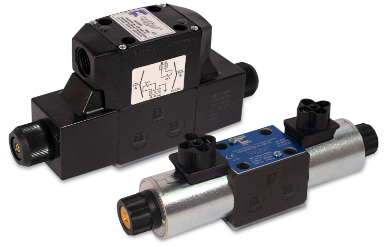
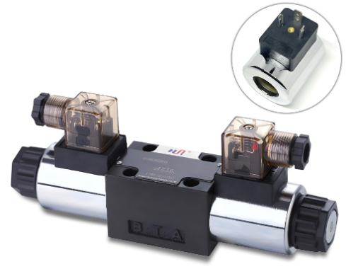
A hydraulic solenoid valve uses electromagnetic force to control hydraulic fluid flow through mechanical valve actuation. When electrical current energizes the solenoid coil, it generates a magnetic field that moves a plunger or armature. This movement opens or closes internal passages, directing hydraulic fluid to specific circuits or actuators.
The fundamental components include the solenoid coil, which converts electrical energy to magnetic force; the armature or plunger, which moves in response to the magnetic field; the valve body containing fluid passages; and the spool or poppet, which controls flow paths. Spring mechanisms typically return the valve to its default position when power is removed.
Poppet-type valves feature a movable seal that either blocks or opens a single flow path. These designs excel in applications requiring tight shut-off with minimal internal leakage, commonly used for load-holding or isolation functions. Poppet valves typically handle pressures up to 5,000 PSI with flow rates from 1.5 to 40 liters per minute.
Spool-type valves utilize a cylindrical spool that slides within a bore, uncovering different ports to create multiple flow paths. This configuration enables 2-way, 3-way, 4-way, and even 6-way flow patterns for complex hydraulic functions. Spool valves offer versatility in directional control but may have slightly higher internal leakage compared to poppet designs.
American manufacturers produce various flow control valve configurations to meet different application requirements. The flow control valve hydraulic category encompasses multiple designs, each optimized for specific performance characteristics.
Pressure-compensated flow control valves maintain constant flow rate regardless of pressure variations upstream or downstream. An internal compensator spool adjusts the valve opening to counteract pressure changes, ensuring consistent actuator speed even under varying loads. These valves typically operate from 0 to 3,000 PSI with flow ranges up to 90 GPM.
Priority flow valves direct a controlled flow amount to a primary circuit while diverting excess flow to secondary functions. This three-port design proves especially valuable in mobile hydraulic systems where steering requires priority flow allocation regardless of other hydraulic demands. Construction equipment and agricultural machinery commonly employ priority flow valves for reliable steering response.
Flow divider/combiner valves split inlet flow into multiple equal output streams or combine multiple inputs into a single output. Pressure compensation on each output maintains flow division accuracy even when individual circuits experience different load pressures. Applications include synchronized cylinder movement in material handling equipment and maintaining equal drive speeds for multiple hydraulic motors.
The electronic hydraulic flow control valve represents recent technological advancement, replacing mechanical adjustment mechanisms with electronic proportional control. These valves receive command signals from programmable logic controllers or dedicated electronic control units, enabling remote flow adjustment and integration with automated systems. Electronic flow controls can modulate from zero to maximum flow continuously, providing precise speed control for hydraulic actuators in manufacturing automation and mobile equipment.
Manufacturing sectors utilize hydraulic flow valves extensively for controlling metalworking machinery, injection molding equipment, and assembly line automation. In press operations, flow control valves regulate ram speed during approach, pressing, and retraction cycles. Precise flow regulation minimizes shock loading while maximizing production throughput.
Construction equipment relies heavily on hydraulic solenoid valves for excavator boom control, crane operation, and loader bucket positioning. The hyd flow control valve systems in these machines must withstand harsh environmental conditions including temperature extremes, vibration, and contamination exposure. American-made valves for construction applications typically feature corrosion-resistant coatings and sealed electrical connections meeting IP65 or IP67 protection ratings.
Agricultural machinery incorporates flow valve hydraulic systems for implements including adjustable plows, harvester headers, and irrigation controls. Flow control enables operators to match implement speed to ground speed and crop conditions. Tractors with multiple remote hydraulic circuits use priority flow control to ensure steering remains responsive regardless of implement demand.
Aerospace applications demand the highest reliability standards, where hydraulic flow control valves regulate fuel flow, actuate flight control surfaces, and operate landing gear systems. American manufacturers serving aerospace markets maintain AS9100 certification and produce valves meeting stringent MIL-SPEC requirements. These valves operate reliably across temperature ranges from -65°F to +275°F while maintaining precise flow regulation.
American-manufactured hydraulic solenoid valves span a wide specification range to accommodate diverse application requirements. Pressure ratings extend from 300 PSI for light-duty applications to 5,000 PSI for demanding industrial and mobile equipment. Certain specialized designs handle up to 6,000 PSI for high-pressure hydraulic systems in oil and gas equipment.
Flow capacity varies from miniature valves handling 1 GPM for precision laboratory equipment to large industrial valves rated for 210 GPM in heavy machinery. The hydraulic adjustable flow control valve category typically offers adjustment ranges from zero to rated maximum flow, with common sizes including 0-10 GPM, 0-30 GPM, and 0-90 GPM variants.
Electrical specifications accommodate standard industrial voltages including 12 VDC and 24 VDC for mobile equipment, plus 110-120 VAC and 220-240 VAC for stationary installations. Power consumption ranges from 10 watts for small solenoid coils to 40 watts for larger actuators. Coil configurations include DC voltage options with lower steady-state power draw and AC options with higher initial pull-in force.
Response time, measured as the interval from energization to full valve movement, varies by design type. Direct-acting solenoid valves typically respond within 15-50 milliseconds, suitable for applications requiring rapid switching. Pilot-operated designs may require 50-200 milliseconds but offer higher flow capacity with lower power consumption.
Understanding hydraulic flow control valve diagram configurations helps system designers optimize circuit performance. Basic flow control valve symbols in hydraulic schematics show the valve body, adjustment mechanism, and flow direction indicators. Additional symbols denote features including pressure compensation, reverse free flow capability, and relief valve integration.
A meter-in flow control configuration places the valve upstream of the actuator, regulating flow entering the cylinder or motor. This arrangement provides positive control over extending or accelerating movements but can cause cavitation if the actuator experiences pulling loads. Applications include downward-moving loads and horizontal movements where resistance dominates.
Meter-out flow control positions the valve on the actuator outlet, restricting return flow to the reservoir. This configuration offers better control of loads that try to run away, such as vertically descending cylinders or decelerating rotary actuators. The restriction creates back-pressure that resists load-induced movement.
Bleed-off flow control diverts excess pump flow to the reservoir while the actuator receives only required flow. This approach minimizes heat generation compared to meter-in or meter-out arrangements but requires careful sizing to prevent cavitation. Load-sensing systems often employ bleed-off control for energy efficiency.
The electronic hydraulic flow control valve category represents significant advancement in hydraulic automation. These valves replace manual adjustment knobs with electronically-controlled solenoids that position the flow control element proportional to input current. As current increases from 0 to rated maximum (typically 0-1000 mA), the valve opening increases proportionally, providing infinite adjustment within the flow range.
Integrated position sensors within electronic flow control valves enable closed-loop control, where the valve continuously adjusts to maintain desired flow rate regardless of pressure fluctuations or temperature changes affecting hydraulic oil viscosity. This capability proves particularly valuable in mobile equipment where operating conditions vary widely during a work cycle.
CAN bus communication interfaces allow electronic hydraulic valves to integrate with vehicle control networks, enabling centralized system monitoring and diagnostics. Operators can adjust flow settings through cab-mounted displays rather than manual valve adjustment. Fault detection capabilities alert operators to electrical connection issues, sensor failures, or valve position errors before they cause equipment downtime.
Recent developments in digital hydraulic technology explore replacing traditional proportional valves with arrays of fast-switching on/off valves. This approach potentially improves energy efficiency by eliminating the pressure drops inherent in throttling flow control. However, digital hydraulic systems require sophisticated control algorithms and remain primarily in research and development phases for most applications.
Proper valve selection begins with defining system operating parameters including maximum working pressure, required flow rate range, and actuator type. For cylinder applications, calculate required flow rate by multiplying piston area by desired extension speed. Hydraulic motor applications require flow rate matching to achieve target rotational speed at given motor displacement.
Pressure drop across the valve affects system efficiency and heat generation. Lower pressure drop reduces energy waste but may require larger, costlier valves. American manufacturers typically provide pressure drop curves showing the relationship between flow rate and pressure differential across the valve at various adjustment settings.
Environmental conditions influence valve material selection and sealing requirements. Indoor manufacturing environments with controlled temperature and cleanliness permit standard designs with NBR (nitrile rubber) seals. Outdoor or harsh environment applications need corrosion-resistant housings, typically zinc-nickel plated steel or stainless steel bodies, with Viton seals rated for temperature extremes and chemical exposure.
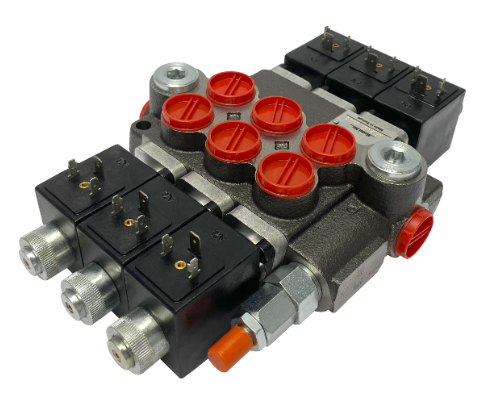
Mounting configuration affects installation complexity and maintenance accessibility. In-line valves install directly within hydraulic hose assemblies for compact integration but may require system disassembly for adjustment access. Subplate-mounted valves bolt to manifolds conforming to NFPA D03 or D05 standards, simplifying replacement and providing convenient adjustment access. Cartridge valves screw directly into manifold cavities for high-density integration in multi-circuit systems.
Hydraulic solenoid valves require periodic maintenance to ensure continued reliable operation. Contamination represents the primary failure mode, as particles in hydraulic fluid can jam valve spools or damage seals. Maintaining filtration systems with 10-25 micron absolute rating prevents contamination-related failures. Filter replacement intervals depend on system operating conditions but typically range from 500 to 2,000 hours.
Electrical connections require inspection for corrosion, loose terminals, or damaged wiring. Outdoor equipment should have electrical connectors sealed with dielectric grease and protected by strain reliefs preventing wire fatigue. Verifying correct voltage at the solenoid coil helps diagnose electrical versus hydraulic problems when valves malfunction.
Abnormal operating temperatures often indicate internal problems. Solenoid coils running excessively hot may have wrong voltage applied, short-circuit conditions, or DC coils being powered with AC voltage. Valve bodies becoming unusually hot suggest pressure drop issues, often caused by partially blocked orifices or incorrect adjustment settings.
When valves fail to shift or respond sluggishly, first verify electrical power reaches the coil with correct polarity for DC valves. Check for contamination blocking valve movement by carefully removing the valve and inspecting internal components. Weak or broken return springs can prevent valves from shifting fully or returning to neutral position after de-energization.
American manufacturers of hydraulic solenoid valves typically maintain ISO 9001 certification, demonstrating adherence to quality management system requirements. This certification requires documented procedures for design control, production processes, inspection protocols, and continuous improvement practices.
Many manufacturers serving automotive and mobile equipment markets hold IATF 16949 certification, the automotive industry’s quality management standard. This certification imposes more stringent requirements including production part approval processes, statistical process control, and measurement system analysis.
Products serving oil and gas applications may conform to API (American Petroleum Institute) standards specifying design, materials, and testing requirements for petroleum industry equipment. Construction equipment applications often require compliance with NFPA (National Fluid Power Association) standards defining mounting patterns, port sizes, and performance criteria.
UL (Underwriters Laboratories) or CSA (Canadian Standards Association) approval indicates electrical components meet recognized safety standards for electrical construction and fire hazard prevention. These certifications prove especially important for valves installed on equipment sold in consumer markets or used in building systems.
The United States hydraulic components market, including solenoid valves, reached approximately $3.2 billion in 2024, with projected growth of 4-5% annually through 2030. Domestic manufacturing maintains significant market share in premium applications where technical support, rapid delivery, and American-made preferences outweigh potential cost advantages of imported products.
Mobile equipment manufacturing, concentrated in Midwest states, drives substantial demand for American-made hydraulic valves. Agricultural equipment manufacturers in Illinois, Iowa, and Wisconsin prefer domestically-sourced components for their proximity to engineering support and just-in-time delivery capabilities. Construction equipment producers similarly value American manufacturers’ responsiveness for prototype development and rapid production ramp-up.
Industry trends emphasize electrification and electronic control integration. Manufacturers increasingly offer valves with electronic proportional control, sensor feedback, and communication bus interfaces. This shift aligns with broader industry movement toward connected equipment, predictive maintenance, and automation.
Environmental regulations drive demand for more efficient hydraulic systems generating less heat and consuming less energy. Flow control valves with improved pressure compensation and reduced internal leakage help equipment manufacturers meet efficiency targets while maintaining performance. Some applications explore electric actuators as hydraulic alternatives, though hydraulics retain advantages in high-force applications requiring compact packaging.
Select a valve with pressure rating at least 25% above your system’s maximum operating pressure. Standard industrial ratings include 3,000 PSI for general manufacturing and 5,000 PSI for mobile equipment. If your system occasionally experiences pressure spikes, consider valves rated for 6,000 PSI to ensure reliability under all operating conditions.
Most American-manufactured flow control valves can mount in any orientation without affecting performance, though manufacturers may specify preferred orientations for optimal air bleeding during initial installation. Check the technical data sheet for specific mounting recommendations, particularly for pilot-operated valves that may have orientation-sensitive pilot sections.
Adjustable flow control valves typically feature a knob, lever, or screw that varies internal orifice size. Turn clockwise to reduce flow and counterclockwise to increase flow. Make adjustments with the system at operating temperature and pressure, observing actuator speed while adjusting. Some valves include graduated scales or flow rate indicators for easier setting repeatability.
Common failure causes include contamination jamming the spool or poppet, coil burnout from electrical overvoltage, seal deterioration from incompatible fluids or excessive temperature, and mechanical damage from pressure spikes. Proper filtration, voltage regulation, compatible seal materials, and shock suppression prevent most failures. Regular inspection and replacement of wear components extends valve service life.
Different applications demand different valve characteristics. High-cycle operations like automated manufacturing require valves with fatigue-resistant solenoids rated for millions of cycles. Mobile equipment needs environmentally sealed valves withstanding vibration, temperature extremes, and exposure to moisture and contaminants. Precision machinery benefits from electronic flow control enabling programmable speed profiles and closed-loop position control.
American manufacturers offer application engineering support helping customers select appropriate valve specifications. This support includes flow calculations, mounting configuration recommendations, and electrical integration guidance. Technical support teams can analyze system performance data to diagnose problems and suggest modifications improving efficiency or reliability.
The decision between American-made and imported valves often balances initial cost against long-term value. Domestic products typically command premium pricing but offer advantages in documentation quality, technical support accessibility, spare parts availability, and lead time reliability. Critical applications where downtime costs exceed component costs usually justify choosing American-manufactured valves for their superior support infrastructure.
Price considerations extend beyond initial purchase cost. Installation expenses, including custom mounting adapters or electrical connectors, vary by valve design. Operating costs reflect energy efficiency and maintenance requirements. Replacement parts availability affects repair costs and downtime duration. Total cost of ownership analysis over expected equipment life provides better basis for selection than purchase price alone.
When equipment operates in remote locations or harsh environments, the robust construction and proven reliability of American-manufactured valves reduces risk of costly failures. Applications include mining equipment, offshore platforms, and agricultural machinery operating far from service facilities. The incremental cost premium for domestic products often represents excellent insurance against expensive downtime.
Prototyping and small production runs particularly benefit from American manufacturers’ flexibility and responsiveness. Domestic companies can often customize standard products or produce small quantities without the minimum order quantities or extended lead times associated with overseas sourcing. This capability accelerates product development cycles and reduces inventory requirements for low-volume specialty equipment.
Sources