
Hydraulic directional control valves vary based on port configuration, spool positions, center type, actuation method, and flow capacity requirements. A single-acting cylinder operating a log splitter needs a 3-way valve with manual control, while a double-acting excavator arm requires a 4-way, 3-position solenoid valve with closed-center configuration. The specific application dictates whether you need 2-way, 3-way, or 4-way porting, how many positions the spool must shift between, and what center condition optimizes your system’s energy efficiency.
The number of ports on a directional control valve directly correlates with the type of actuator it can control. This isn’t arbitrary—it’s driven by the fundamental hydraulic circuit requirements of your equipment.
A 2-way valve functions as an on-off switch with inlet and outlet ports. These work for applications like blocking or allowing flow in auxiliary circuits, but they don’t provide directional control for actuators. Think of them more as isolation valves than directional controllers.
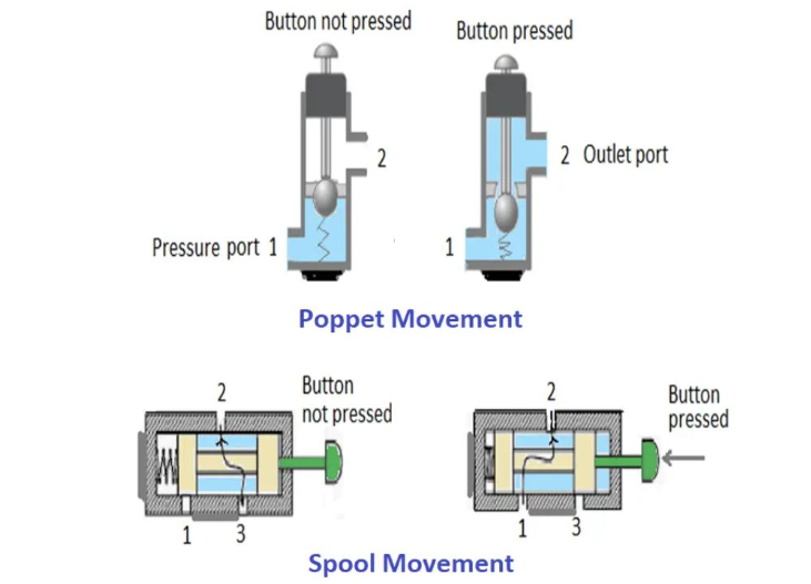
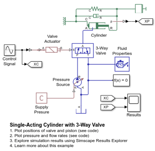
3-way valves add a third port—typically pump, tank, and one work port. This configuration suits single-acting cylinders where gravity or spring force returns the actuator. Agricultural equipment often uses 3-way valves for implements like front-end loaders where the bucket naturally lowers under its own weight. The valve only needs to supply pressure for lifting; lowering happens when pressure releases to tank.
4-way valves represent the most common configuration in mobile and industrial hydraulics. With pump, tank, and two work ports (typically labeled A and B), these valves can pressurize and exhaust both ends of a double-acting cylinder. Construction machinery relies heavily on 4-way valves—excavator arms, dozer blades, and crane booms all need controlled extension and retraction in both directions.
The port sizing matters just as much as quantity. A valve rated for 11 GPM won’t adequately serve a system demanding 25 GPM—you’ll create pressure drops, generate excessive heat, and potentially damage components. Conversely, oversizing wastes money and can make manual valves harder to shift due to increased fluid forces on the spool.
Position count determines how many distinct operational states your valve can achieve. The standard options are 2-position and 3-position configurations, though mobile equipment sometimes uses 4-position valves for specialized applications.
2-position valves shift between two states: typically “extend” and “retract” for cylinders, or “rotate clockwise” and “rotate counterclockwise” for motors. These work well when you need simple reciprocating motion without a hold position. Log splitters commonly use 2-position valves—the cylinder either extends to split wood or retracts to reset.
3-position valves add a neutral center state, which fundamentally changes how the system behaves. The center position can block all ports, connect certain ports, or create specialized flow paths depending on the spool design. This middle position is where center configuration becomes critical—more on that shortly.
Industrial presses frequently use 3-position valves. The operator can extend the press ram (position 1), hold it at any point during the stroke (neutral center with ports blocked), or retract it (position 2). This controllability is impossible with a 2-position valve.
4-position valves typically add a “float” state where work ports connect to tank while blocking the pump. This allows external forces to move the actuator freely. Material handling equipment like forklifts uses float positions to let gravity lower loads without pump power, saving fuel and reducing heat generation.
For 3-position valves, the center configuration determines what happens when the valve returns to neutral. This seemingly minor detail has major implications for pump selection, energy efficiency, and system architecture.
Open center valves direct pump flow straight to tank in the neutral position while blocking work ports. This design suits fixed-displacement gear pumps common in agricultural equipment. When no function is active, the pump circulates fluid at minimal pressure rather than building pressure against a relief valve. Multiple open-center valves can be arranged in series, with priority given to upstream functions.
Agricultural tractors typically use open-center systems. When the tractor is simply driving (no implements active), hydraulic fluid circulates freely through the valve stack back to tank. This prevents excessive heat buildup and reduces parasitic power losses. However, open-center systems can’t operate multiple functions simultaneously at full capacity—the first valve to shift gets full flow.
Closed center valves block all ports in neutral. The pump dead-heads against its compensator or relief valve, maintaining system pressure. This configuration works with variable-displacement or pressure-compensated pumps. Each valve can operate independently without affecting others, making closed-center ideal when you need simultaneous multi-function control.
Modern construction equipment predominantly uses closed-center systems. An excavator operator can swing the cab, extend the boom, and curl the bucket simultaneously—each function receives the flow it needs. Load-sensing systems have refined closed-center operation further, reducing standby losses by lowering pressure when no function demands it.
Tandem center valves block work ports A and B while connecting pump to tank. This allows the pump to unload to tank pressure in neutral while locking the cylinder in position (though not rigidly—internal leakage will eventually allow drift under load). Tandem centers work well for holding cylinders stationary between operations without continuously circulating pump flow.
Industrial clamp-and-hold fixtures often employ tandem-center valves. During the machining operation, the workpiece stays clamped with minimal power consumption. When it’s time to release and reload, the valve shifts to exhaust the clamp cylinder.
Float center valves block the pump port while connecting work ports A and B to tank. This allows the cylinder to move freely in response to external forces without hydraulic resistance. Material handling equipment uses float centers when lowering loads under gravity control, often combined with counterbalance valves for speed regulation.
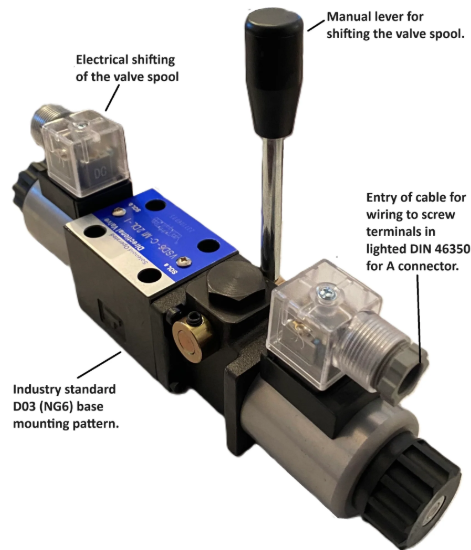
How you shift the valve depends on whether your application needs manual, automatic, or remote control. Each actuation method brings distinct advantages and limitations.
Manual actuation via levers or handles costs less and requires no external power. Small tractors, utility trailers, and simple hydraulic equipment rely on manual valves. The operator gets direct tactile feedback—you can feel when pressure builds or when a cylinder reaches the end of stroke. However, manual valves require the operator to be within arm’s reach, limiting machine design flexibility.
Manual directional control valves dominate the agricultural attachment market. A farmer operating a 3-point hitch doesn’t need electronic sophistication—a robust lever-operated valve provides reliable control for decades with minimal maintenance. The same goes for utility trailers with hydraulic lifts and wood splitters.
Solenoid actuation enables electrical remote control, essential for automated systems and operator stations located away from the valve manifold. Modern construction equipment puts the operator in a climate-controlled cab meters away from the hydraulic manifold—solenoid valves make this possible. The electrical signals are easier to route than mechanical linkages.
Solenoids require specific voltage (typically 12VDC or 24VDC for mobile equipment, 110VAC or 220VAC for industrial applications). They draw significant current during the initial shift (inrush current) but less during holding. Duty cycle limitations apply—continuous-duty solenoids can remain energized indefinitely, while intermittent-duty solenoids need periodic de-energization to avoid overheating.
Hydraulic pilot actuation uses low-pressure pilot signals to shift larger main spools. This allows small pilot valves (often solenoid-operated) to control high-flow main stages. Pilot operation also enables proportional control—varying the pilot pressure modulates the main spool position, giving infinitely variable speed control rather than just on-off operation.
Large mobile equipment and industrial hydraulics favor pilot-operated valves when flows exceed 30 GPM. A pilot-operated system can control 100+ GPM with a small electrical solenoid shifting a pilot valve, which then directs pilot pressure to shift the main spool. The solenoid never sees the main flow forces, extending service life and reliability.
Mechanical actuation via cams, rollers, or springs suits specialized sequencing applications. A cam follower might shift a valve when a machine element reaches a specific position, or a spring might return the valve to neutral when pilot pressure drops. These actuation methods are less common in general applications but solve specific control challenges elegantly.
Valve flow capacity must match system requirements, but this isn’t just about maximum GPM. Pressure drop through the valve at operating flow matters significantly for overall system efficiency.
Valve manufacturers rate flow capacity at specific pressure drops, commonly 100 PSI or 150 PSI. A valve rated for 25 GPM at 100 PSI drop will flow more at higher differential pressures, but this indicates you’re undersized—you’re wasting energy creating pressure drop rather than doing useful work.
As a rule of thumb, select valves that operate at 50-75% of rated capacity during normal use. This provides headroom for peak demands while minimizing pressure losses. A system requiring 20 GPM continuous flow should use a valve rated for 25-30 GPM to maintain efficiency.
Undersized valves create multiple problems beyond just flow restriction. The high fluid velocities generate heat through turbulence. Metal erosion accelerates at valve ports and metering edges. Control becomes sluggish as pressure losses rob the actuators of force. In extreme cases, cavitation can occur on the downstream side of restrictions, damaging internal components and creating noise.
Oversized valves present different challenges. Manual valves become difficult to shift because larger spools have more surface area exposed to system pressure—the operator must overcome greater forces. Costs increase unnecessarily. Manifold space grows. For electrically operated valves, larger solenoids draw more power.
Mobile equipment manufacturers often standardize on specific valve sizes across product lines—typically 11 GPM, 20 GPM, and 30 GPM ratings for small-to-medium machines. This simplifies inventory, service parts, and operator training. Industrial applications might use larger valves (40+ GPM) or modular sectional designs where multiple sections stack together.
Hydraulic systems operate at pressures ranging from 500 PSI for utility applications to 5,000+ PSI for heavy industrial equipment. Your directional control valve must safely contain maximum system pressure with appropriate safety margins.
Standard mobile hydraulic valves typically rate to 3,000-3,600 PSI (210-250 bar). This suits most agricultural and light construction equipment operating at 2,000-2,500 PSI. The safety margin allows for pressure spikes during rapid deceleration or when cylinders reach hard stops.
Industrial applications often demand higher ratings. Steel mill equipment, heavy presses, and large injection molding machines may operate at 3,500-5,000 PSI, requiring industrial-duty valves rated to 5,000-7,000 PSI. These valves use heavier sections, hardened materials, and tighter tolerances to contain the extreme forces.
Pressure ratings also affect center port back-pressure limits. Some valve center configurations create trapped volumes that can be pressurized externally. The valve must safely contain these pressures without leaking or structural failure. Manufacturers specify maximum back-pressure ratings for each port in each position.
Real-world applications demonstrate how these specifications combine to serve specific needs.
A log splitter uses a 3-way, 2-position, manually operated valve with open center. The single-acting cylinder extends to split the log (valve shifted), then a spring or gravity returns it (valve in neutral releases pressure). Flow rate: 11-16 GPM. Pressure: 2,500 PSI. The simplicity minimizes cost while providing all needed functionality.
An agricultural tractor three-point hitch system employs a 4-way, 3-position, manually operated valve with open center. The double-acting cylinder needs controlled raising and lowering. Open center integrates with the tractor’s fixed-displacement pump. Flow rate: 16-25 GPM. Pressure: 2,000-2,500 PSI. Tandem center would also work here, providing a hold position for transport.
An excavator boom circuit requires a 4-way, 3-position, pilot-operated valve with closed center. The double-acting cylinder must extend and retract with precise control. Closed center allows simultaneous operation with other functions (stick, bucket, swing). Load-sensing pilot operation provides proportional speed control. Flow rate: 40-80 GPM. Pressure: 3,500-4,500 PSI.
An industrial hydraulic press utilizes a 4-way, 3-position, solenoid-operated valve with tandem center. The double-acting cylinder extends to apply pressing force, holds under pressure during the forming operation, then retracts. Tandem center unloads the pump during the idle state while maintaining cylinder position. Flow rate: 15-30 GPM. Pressure: 2,000-3,000 PSI.
A mobile crane outrigger uses a 4-way, 3-position, solenoid-operated valve with closed center. The double-acting cylinders must extend firmly to stabilize the crane (closed center prevents drift under load). Each outrigger operates independently. Flow rate: 10-15 GPM. Pressure: 3,000-3,500 PSI. Counterbalance valves at the cylinders provide additional load holding.
When specifying a directional control valve, work through these questions systematically:
Actuator type: Single-acting or double-acting? This determines whether you need a 3-way or 4-way valve. Single-acting means 3-way; double-acting means 4-way.
Positional requirements: Do you need just extend/retract, or also a neutral hold position? Basic on-off operation uses 2-position valves. Need to hold mid-stroke? You need 3-position.
Pump type: Fixed or variable displacement? Fixed-displacement pumps pair naturally with open-center valves. Variable-displacement or load-sensing pumps work with closed-center.
Multi-function operation: Will multiple cylinders or motors operate simultaneously? If yes, closed center provides independent control. If functions operate sequentially, open center costs less.
Energy efficiency priority: How much time does the system spend idle? Systems with long idle periods benefit from open or tandem centers that unload the pump. High-duty-cycle applications justify closed-center systems with load sensing.
Control precision: On-off control or proportional speed control? Standard switching valves provide on-off. Proportional or servo valves enable infinitely variable positioning.
Operating environment: Indoors with clean power, or mobile in harsh conditions? Clean industrial environments allow electronics. Outdoor mobile equipment needs robust solenoids rated for vibration, temperature extremes, and voltage fluctuations.
Service access: Can the valve mount near the operator, or must it be remote? Manual valves require accessible mounting. Solenoid valves can mount anywhere you can route wiring.
Flow and pressure requirements: What cylinder speed do you need, and at what force? This drives valve size and pressure rating selection. Calculate cylinder area, desired extend/retract speeds, and required force to determine specifications.
Directional control valves typically handle contamination better than other hydraulic components, but proper maintenance still matters for reliable service life.
Filtration is critical. Modern mobile valves tolerate contamination to ISO 18/16/13, but finer filtration extends life. Particles above 10 microns can wedge between spool and bore, causing sticking or sluggish shifting. Return-line filters at 10-micron absolute rating protect valves from wear debris circulating through the system.
Valve position affects service requirements. Vertical mounting can lead to gravity-induced spool drift in manual valves with weak detents. Horizontal mounting is preferred when possible. For solenoid valves, mounting orientation affects coil heat dissipation—check manufacturer specifications.
Seal replacement represents the primary maintenance task. Dynamic seals (O-rings on spools) wear from reciprocating motion. Static seals (at ports and mounting surfaces) can harden or crack with age. Most mobile valves use standard O-ring sizes, but industrial valves may require manufacturer-specific seal kits.
Electrical maintenance for solenoid valves includes checking coil resistance (typical 20-200 ohms depending on voltage), ensuring clean electrical connections, and verifying appropriate voltage delivery. Voltage drops due to corroded connections or undersized wire cause weak shifting forces and shortened coil life.
Manual valves need periodic lubrication of pivot points and handle mechanisms. Exposed linkages should be greased to prevent binding. Stainless steel or zinc-plated handles resist corrosion better than painted steel in outdoor applications.
Yes, but it’s inefficient. Connect the single-acting cylinder to one work port and plug the other work port. The valve will function, but you’re paying for capabilities you don’t need. A 3-way valve costs less and eliminates the unnecessary port.
Cold hydraulic oil becomes viscous, increasing the force needed to shift spools. This affects manual valves more than powered valves. Solutions include using appropriate winter-grade hydraulic fluid (lower viscosity at low temperatures), installing immersion heaters in the reservoir, or switching to pilot-operated valves where a small solenoid shifts a pilot valve rather than directly moving the main spool.
Symptoms include slow cylinder speeds despite adequate pump flow, excessive heat at the valve body, and pressure drops between pump and actuator. Measure pressure at the pump (system pressure) and at the valve work ports during operation. If the pressure drop exceeds 150 PSI at the valve during flow, you’re likely undersized.
Many spool-type mobile valves can be rebuilt using seal kits. The spool typically shows minimal wear since it rides on a thin oil film. However, if the bore is scored or the spool shows grooving from contamination damage, replacement becomes necessary. Industrial valves with hardened spools and specialized coatings often justify rebuilding by specialized shops.
Hydraulic directional control valve selection comes down to matching valve characteristics with application requirements. Port configuration follows from actuator type. Position count depends on whether you need a neutral state. Center configuration aligns with pump type and energy priorities. Actuation method suits control location and automation needs. Flow and pressure ratings must provide adequate capacity with appropriate safety margins.
The market trends toward greater electronic integration. Solenoid valves with integrated controllers now provide proportional control, pressure feedback, and diagnostic capabilities. CAN bus communication allows centralized control of multiple valves from a single operator interface. These advances bring precision and flexibility but add complexity and cost.
For many applications, simpler is better. A manually operated, open-center valve on a small tractor provides decades of reliable service with minimal maintenance. The valve costs less than $100 and requires no electrical system. When that directional control valve matches the application’s actual needs—rather than over-specified features—it delivers optimal value.
The key is understanding your specific needs: actuator requirements, operational cycle, control preferences, and budget constraints. Match these against valve specifications systematically, and you’ll select equipment that performs reliably for years.