
“Directional control valves” don’t actually switch direction, but rather switch flow paths: by applying operating force to overcome resistance, moving the spool, and changing flow path conditions — closing one flow path (reducing the opening to zero) and opening another flow path (increasing the opening from zero). As for the direction of fluid flow, it depends on the pressure difference between the two ends of the flow path — the ports. Oil always flows from the high-pressure port to the low-pressure port. However, in the following introduction, we will follow convention and still refer to this type of valve as a directional control valve.
Directional control valves are generally externally controlled, switched by the operator as needed — directly through manual, mechanical, or electrical control, or indirectly through hydraulic or pneumatic actuation.
Directional control valves are of the on-off type, meaning they normally do not remain continuously in an intermediate position; switching is completed within a short time (typically 10-100ms). During normal operation, flow paths have only two states: blocked and open. Their pressure drop – flow characteristics are similar to fixed orifices, roughly following a parabolic curve.
Directional control valves often have multiple different flow paths. Different flow path shapes and sizes may result in different hydraulic resistances, so a complete representation of pressure drop – flow characteristics sometimes requires multiple curves.
For directional control valves, it is generally desirable to have large flow capacity and small inlet-outlet pressure drop. The nominal flow rate refers to the flow that can pass through at a certain pressure differential between inlet and outlet. Since flow rates differ at different pressure differentials, flow capacity cannot be compared solely by nominal flow rate; comparison must be made at the same test pressure differential. Some product catalogs do not provide nominal flow rates, requiring reference to pressure drop – flow curves.
Chapter 7: Various Types of Hydraulic Valves
Additionally, whether reliable switching is possible requires consulting the operating range curves; nominal flow rate does not guarantee this.
The allowable pressure for each port is generally the same (except for some valves where the T port is lower), but whether reliable switching can occur at this pressure requires examining the operating range curves.
Operating range curves are used to indicate that the directional control valve can reliably switch from one working position to another within that range. If actual parameters (pressure, flow) exceed the range, the driving force is insufficient to overcome resistance, and switching speed will slow down or switching may become impossible.
The core task of a directional control valve is to switch flow paths: it needs to move the spool to close one flow path and open another while flow exists in that path. Forces resisting spool movement include spring force, static pressure, and flow force that varies with spool displacement (see Section 4.2) — the latter being the main interference factor.
Manually operated spools: Designers will use lever principles (such as handles, foot pedals); normal operation requires only small force, and increased resistance can be overcome manually.
Mechanically operated valves, hydraulically operated valves (pilot-assisted drive): Generally no switching problems (pilot pressure for high-pressure valves only needs 2-3 MPa).
Direct-acting solenoid valves: Prone to switching problems — because solenoid design often uses maximum thrust (to reduce cost, control volume, reduce heat generation), and DC solenoids lack the redundant thrust of AC solenoids that “sharply increase current when closing is difficult.”
Flow force reaches maximum at a certain opening amount, so a “transition threshold” condition may occur (neither maximum allowable flow nor maximum allowable pressure), preventing spool switching; this needs to be expressed using the operating range.
Standard recommendation: If switching is difficult 2 out of 10 repeated attempts, it is determined to be out of range; there are also recommendations to repeat tests ≥3 times and plot operating range diagrams.
Manufacturer operating range curves are usually based on laboratory conditions: clean mineral oil, oil temperature 40°C, viscosity 32mm²/s, input voltage at 90% of rated voltage; reputable manufacturers will use more stringent conditions.
Hydraulic Valve Analysis
If a product only provides maximum allowable flow (higher than nominal flow) and allowable pressure without an operating range diagram, testing is needed to verify switching reliability at maximum flow + allowable pressure combinations; for applications with large actual condition fluctuations, conservative selection is recommended.
When selecting directional control valves, attention must be paid to the connection status during switching:
Positive overlap (overcenter): During switching, port P is briefly blocked; pump output must overflow through the relief valve, easily forming instantaneous high pressure; if exceeding the valve’s operating range, the spool may stick.
Negative overlap (undercenter): No such problems.
Directional control valves have various connection and mounting methods:
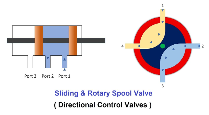
Named by number of spool working positions + number of valve body ports (e.g., “2-position 3-way”: 2 working positions, 3 ports).
Number of working positions: Solenoid directional valves are mostly 2-position or 3-position, rarely 4-position; manual/mechanical valves can theoretically achieve more positions.
Number of ports: Main flow has at most 4 ways; 5-way and 6-way are mostly for control pressure; 2-way valves can only open/close flow paths (no direction switching), but are conventionally classified as directional valves.
Most directional valves use sliding spools (with leakage); sliding cone directional valves (mainly 2-way) can achieve essentially zero leakage.
Among these, 3-position 4-way directional control valves are most widely used, capable of directly controlling double-acting hydraulic cylinder movement.
Hydraulic Valve Analysis
The ports of 3-position 4-way valves are typically: A and B connected to the two chambers of the hydraulic cylinder, P connected to pump outlet, T connected to tank; working positions are mostly “P to A, B to T” or vice versa.
Center position function refers to the flow path condition of a 3-position 4-way valve when not operating. Various types have been developed to accommodate different scenarios. For example:
M-type: A and B ports blocked (reducing hydraulic cylinder movement under load), P to T (pump oil returns directly to tank, reducing energy loss).
P, H, Y types (A, B to T): Suitable for scenarios where hydraulic cylinder outlets are blocked by pilot-operated check valves/counterbalance valves (control pressure side needs to lose pressure to prevent accidental opening).
Different center position functions result in different spool shapes, which affect pressure drop – flow characteristics.
Sliding spools have leakage; poppet spools can achieve zero leakage, but a single poppet spool can control at most 3 ways; controlling 4 ways requires combining two spool sections (complex structure); dashed lines in graphic symbols represent transition states.
Chapter 7: Various Types of Hydraulic Valves
Nominal diameter and flow of ordinary subplate-mounted solenoid directional valves: 6mm diameter (60-90 L/min), 10mm diameter (120 L/min).
In large flow, high-pressure scenarios, flow force and driving force requirements increase. Direct drive requires large solenoids (high cost, more heat generation), so valves with diameter ≥16mm use electro-hydraulic directional valves (pilot stage is solenoid directional valve, main stage is hydraulic directional valve), with larger flow capacity.
Solenoid directional valves have short switching times; applying flow to a stationary hydraulic cylinder causes startup jerks. Electro-hydraulic directional valves can add orifices or one-way throttle valves between the pilot stage and main stage, extending main stage switching time to reduce jerks.
Chapter 7: Various Types of Hydraulic Valves
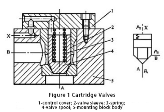
Cover plate cartridge valves (abbreviated as “2-way valves”) have 2 ports (A, B) and 1 control port (X), used to control flow path on/off.
Spool position is determined by forces:
Downward forces: spring force, control port pressure
Upward forces: port A pressure, port B pressure
When the sum of forces corresponding to port A pressure and port B pressure is greater than the sum of forces corresponding to control port pressure and spring force, the spool moves up and the A-B flow path opens; otherwise, the spool is pressed down and the flow path closes.
Hydraulic Valve Analysis
The on/off of 2-way valves depends not only on spool dimensions but also on pressures at each port and spring force.
Subplate-mounted directional valves (spool type) require thick, long spools for large flows, which are difficult to machine and costs increase steeply with diameter. Cover plate cartridge valves have simple functions with short spools/bores, are easy to machine with large flow capacity. For flows >400 L/min, costs are lower than subplate-mounted valves; they have now replaced subplate-mounted valves with diameter ≥25mm.
2-way valves must work with pilot valves; combining with different pilot valves can achieve various functions.
Combinations of 2-way valves can replace 3-position 4-way valves to control hydraulic cylinders.
Chapter 7: Various Types of Hydraulic Valves
Using a 3-position 4-way valve as pilot to control 4 two-way valves, only 3 operating conditions; center position function determines on/off when hydraulic cylinder is stationary.
Problem: 2-way valve on/off is affected by multiple factors, prone to asynchronous operation, causing “pressure buildup” (back pressure chamber not connected to tank while drive chamber already connected to pump), “all paths open” (pump connected to both hydraulic cylinder chambers), and other abnormalities, leading to hydraulic cylinder malfunction.
Solution: Adjust spring stiffness/preload, spool shape, add damping orifices; or provide each 2-way valve with an independent 2-position 3-way pilot valve, combining multiple operating conditions, coordinating with electronic timing controllers to adjust switching sequence and avoid abnormalities.
Two 3-way valves can replace a 3-position 4-way valve, offering greater flexibility.