
A relief valve the size of your fist is the only thing standing between a smooth operation and a blown hose, a cracked cylinder, or a five-figure repair bill. Most operators don’t think twice about this component — until it fails.
Hydraulic pressure relief valves cap maximum system pressure and divert excess flow back to the reservoir. Misadjust one, neglect one, or install the wrong size, and you’ll silently drain performance, overheat your fluid, and shorten the life of every pump, motor, and seal in the circuit.
This guide covers how relief valves work, why they fail, and what to do about it — based on decades of combined shop experience, not textbook theory.
HYDRAULIC INJECTION INJURY WARNING
Hydraulic fluid escaping through a pinhole leak at 2,000+ PSI can penetrate skin and inject oil deep into tissue. This injury often looks minor on the surface — a small puncture — but without emergency surgery within hours, it can lead to amputation or death.
Never use your hand to feel for leaks. Never loosen fittings under pressure. Even after shutdown, accumulators and trapped pressure in closed circuits can retain dangerous energy. Always depressurize, lock out/tag out, and verify zero pressure with a gauge before touching any hydraulic connection.
A hydraulic pressure relief valve protects the system by automatically diverting excess fluid flow back to the reservoir whenever pressure exceeds a preset limit. Every hydraulic circuit powered by a fixed-displacement pump requires at least one relief valve — without it, a stalled actuator or closed directional valve will dead-head the pump, and the resulting pressure spike will find the weakest component in the circuit. Relief valves come in two main designs: direct-acting valves, which use a spring-loaded poppet and respond quickly but allow 300–500 PSI of pressure override in typical systems, and pilot-operated valves, which use a small pilot stage to control a larger main stage and hold pressure within roughly 50 PSI across their full flow range. In most industrial and mobile hydraulic systems above 15 GPM, pilot-operated relief valves are the standard choice for tighter pressure regulation.
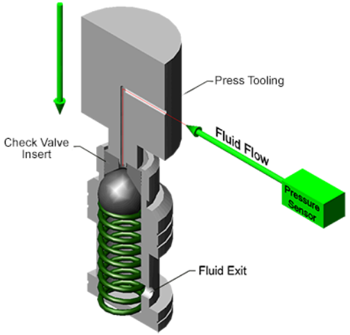
Inside every relief valve sits a spring-loaded poppet or spool. System pressure pushes against this element; the spring holds it shut. The moment pressure exceeds the spring’s preset force — the cracking pressure — the poppet lifts off its seat. Oil reroutes back to tank.
Pressure drops. Spring pushes the poppet back down. Valve closes. That cycle can repeat thousands of times per minute. Every time an excavator bucket hits rock, every time a press reaches full tonnage, every time an operator dead-heads a cylinder — the relief valve is doing its job.
Direct-acting valves use a single spring pushing directly on the poppet. Compact, fast, common in circuits under 15 GPM. The downside is pressure override — system pressure climbs as flow through the valve increases. In a 10 GPM system, expect 300–500 PSI of override between cracking and full-flow relief. That’s a wide spread, and it means your actual relief pressure depends on flow rate, not just the adjuster setting.
Pilot-operated valves use a small pilot stage controlling a larger main stage. The result: much tighter regulation. A good pilot-operated valve holds within 50 PSI across its full flow range. These are standard in most industrial and mobile systems above 15 GPM.
If you’re sourcing replacement hydraulic valves, matching the valve type to your circuit design is non-negotiable. Swapping a pilot-operated valve for a direct-acting one in a high-flow circuit will give you ugly pressure override and unpredictable actuator behavior.
| Valve Type | Typical Flow Range | Pressure Override | Best For |
|---|---|---|---|
| Direct-Acting (Poppet) | 0–15 GPM | 300–500 PSI | Pilot circuits, low-flow branches, subcircuit protection |
| Pilot-Operated (2-Stage) | 15–200+ GPM | 30–75 PSI | Main system relief, high-flow industrial/mobile circuits |
| Differential Poppet | 5–60 GPM | 100–200 PSI | Mid-range circuits needing better override than standard poppet |
In our experience, the failures that cost the most money aren’t the dramatic blowouts. They’re the slow leaks and low-pressure conditions that go unnoticed for weeks.
Pressure builds with no escape. Hoses burst. Seals blow. Pump shafts snap. In severe cases, cylinder tubes crack and pressurized oil sprays at 3,000+ PSI.
Critical reminder: Even after engine shutdown, accumulators and load-induced backpressure can keep circuits at full working pressure. A stuck relief valve combined with residual stored energy is one of the most dangerous conditions in hydraulic maintenance. Verify zero pressure at the gauge before disassembly — every time.
Relief cracks at 1,800 PSI instead of the 3,000 PSI setting. Cylinders lose force. Cycle times stretch. Operators compensate by running harder, which accelerates pump and motor wear. Looks like a “whole system” problem. Actually one worn spring.
From the Shop Floor
Last quarter we diagnosed a LiuGong 920E excavator that came in with “weak digging force — suspect main pump failure.” The customer was quoted $12,000+ for a pump rebuild elsewhere. We hooked up a gauge set and found the main relief was cracking at 2,400 PSI instead of the 4,600 PSI spec. Pulled the valve — the pilot orifice was 80% blocked with varnish from overheated oil. Cleaned the orifice, replaced the pilot poppet spring, reset to spec. Total parts cost: under $85. Machine went back to full digging force the same day. The pump was fine all along.
Contamination lodges between poppet and seat. The valve never fully closes. That constant trickle generates heat. The math:
HPloss = (PSI × GPM) ÷ 1,714
Example: 3,000 PSI × 2 GPM leakage = 3.5 HP of continuous waste heat
Over an 8-hour shift, that’s your oil getting cooked. Accelerated seal degradation. Shortened fluid life. Increased system-wide wear. All from a valve that “mostly” closes.
Rapid poppet oscillation — you’ll hear a high-pitched buzz or rattle from the valve body. It accelerates seat wear and creates a leak path within weeks. Chattering usually signals a system-level issue: pressure spikes from rapid valve shifting, cylinder end-of-stroke impacts, or undersized piping. Fix the cause, not just the symptom.
The following procedure aligns with standard practices referenced by IFPS (International Fluid Power Society) certified technicians. Always consult your machine’s OEM service manual for model-specific procedures.
Grab the hydraulic schematic. Identify which relief valve serves which circuit — on complex equipment, there may be five or more, each set to different pressures. No schematic available? Contact the OEM or check the nameplate data on the valve itself for a model number you can cross-reference.
1. Install a calibrated pressure gauge at the test port between pump and relief valve. No port? Tee into the valve inlet line. A quality hydraulic pressure test kit with the right gauge range and fittings saves time and prevents adapter headaches.
2. Back the adjustment screw fully counterclockwise (toward minimum). Start from a known zero baseline.
3. Slowly turn clockwise while watching the gauge. Pressure climbs until the valve cracks — gauge needle stabilizes or drops slightly. That’s your cracking pressure. Compare to spec.
4. Continue adjusting to match the specified full-flow relief pressure. Lock the adjuster nut. Run the circuit through several full cycles. Verify pressure holds steady under load.
If you can’t reach spec no matter how much you adjust, the internals are worn. Time for a rebuild kit or replacement.
Rule of Thumb for Pressure Setting
If you don’t have the OEM schematic, set your main system relief valve at 10–15% above maximum working pressure, or roughly 200–300 PSI above the highest normal operating pressure in that circuit. This provides enough margin to prevent nuisance tripping during pressure spikes while still protecting the system. Example: if your circuit normally operates at 2,500 PSI, set the relief between 2,750–2,875 PSI. This is an approximation — always confirm with OEM data when available.
Relief valves last decades or months. The difference is how the rest of the system treats them.
Keep your oil clean. Contamination causes over 70% of hydraulic component failures. Relief valves — with their precision-ground seats — are especially vulnerable. Target ISO 4406 cleanliness of 18/16/13 or better. Change filters on schedule. Run oil analysis. When sourcing hydraulic spare parts and filters, the cost difference between a quality filter and a budget one is negligible compared to the valve damage it prevents.
Stop using the relief valve as a pressure regulator. If your circuit relies on the relief valve opening during normal operation to control pressure, that’s a design problem. Every minute the relief is open, it converts hydraulic power to heat. Use proper pressure reducing valves for branch circuit control. Save the relief for what it’s meant to do — emergency overpressure protection.
Inspect during scheduled downtime. Pull the valve. Check poppet and seat for scoring, erosion, contamination. Measure spring free length against spec. Replace seals. Thirty minutes of inspection prevents thirty hours of unplanned shutdown.
Document everything. Set pressure. Valve location. Last adjustment date. Part number. When a new tech touches the system six months from now, this log prevents guesswork and costly misadjustment.
A relief valve doesn’t operate in isolation. It’s one piece of a complete hydraulic system — pumps, motors, directional valves, actuators, fluid. When the relief misbehaves, the cause could sit anywhere in that chain: a failing pump creating erratic pressure, contaminated fluid from a deteriorating hose, or thermal expansion in a stalled circuit.
Understanding the full family of hydraulic valves — pressure, directional, flow control — makes you a better troubleshooter. The technician who understands how these components interact doesn’t just fix problems faster. They prevent problems from happening.
You can. You shouldn’t. Raising relief pressure above design spec overloads every component downstream — hoses, fittings, seals, the cylinder barrel itself. We’ve seen operators on CAT 320s bump the main relief by 500 PSI “for a little extra power.” Three weeks later: cracked pump housing. The $85 pressure bump turned into an $8,000 pump replacement.
Annually at minimum. Semi-annually for high-duty equipment — presses, shears, injection molding machines. After any major component swap (pump, motor, directional valve), recheck relief settings before returning to production. Pressure settings can shift when adjacent components change the circuit dynamics.
No. A relief valve should be quiet during normal operation because it shouldn’t be opening. Chattering, buzzing, or hissing means the valve is cycling under normal pressure (wrong setting, worn internals) or the system has upstream instability. Diagnose the root cause. Don’t just live with it — the noise is telling you something is wearing out fast.
Check the valve nameplate for a model/part number and cross-reference it with the manufacturer’s catalog for factory pressure settings. If that fails, use the 10–15% rule above as a starting point, then refine based on actual operating conditions. When in doubt, reach out to our engineering team — we can help identify specs for most common valve models.
Pozoom Hydraulic stocks over 7,000 components — relief valves, reducing valves, directional valves, pumps, motors, and spare parts — with technical support to match the right valve to your system.