
A standard 2-way ball valve does one thing: open or close a single flow path. A 3-way adds a third port — and instead of just on/off, you can route flow between different circuit branches using a single quarter-turn handle.
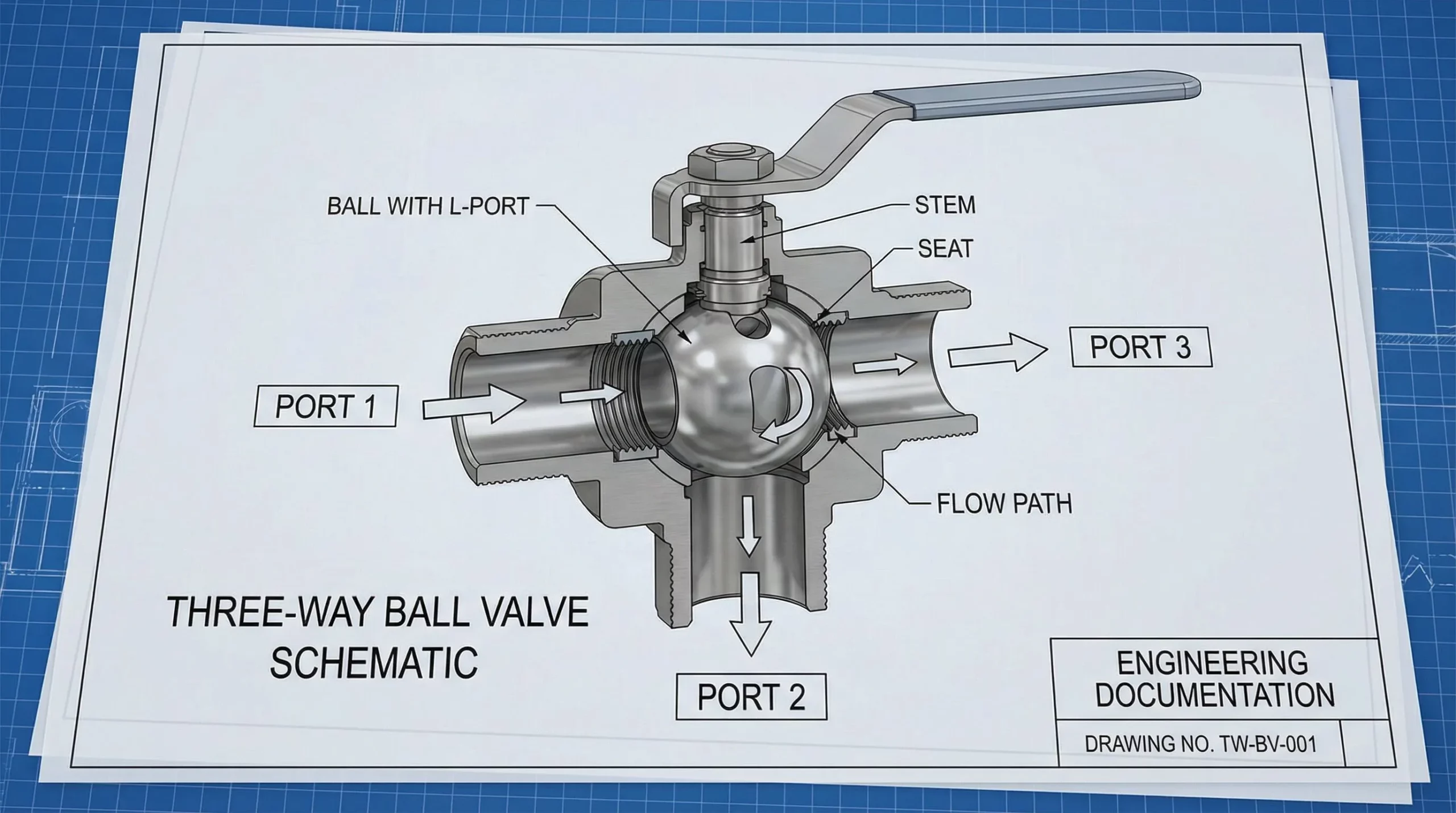
The ball inside a 3-way valve has an L-shaped or T-shaped bore machined through it. When you rotate the handle, the bore aligns with different port combinations. According to Tameson’s engineering guide on 3-way hydraulic ball valves, L-port configurations allow flow between two ports at a time (blocking the third), while T-port configurations can connect all three ports simultaneously for mixing or splitting flow.
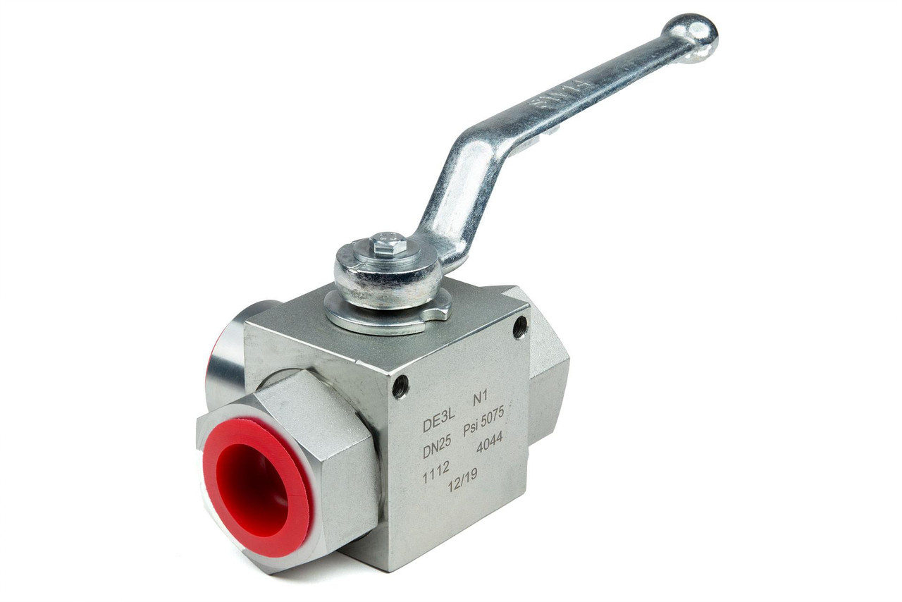
For the 3/4″ NPT, 5,145 PSI model specifically — this is an L-port diverter. It selects between two output paths from one pressure source. The operator turns the lever 90 degrees, and flow redirects. No electronics, no pilot pressure, no external controls. Just a steel ball rotating inside a steel body.
Not all 3-way ball valves are interchangeable. In hydraulic systems, pressure rating, port configuration, and material determine whether a valve survives or fails. Here’s what defines this particular class of valve:
| Parameter | Specification | Why It Matters |
|---|---|---|
| Working pressure | 5,145 PSI (355 bar) | Must meet or exceed maximum system pressure including transient spikes |
| Port size | 3/4″ NPT female thread | NPT taper creates a mechanical seal — requires PTFE tape or pipe dope for leak-free installation |
| Flow path | L-port (diverter) | Routes flow between two outlets; blocks the third. Not suitable for mixing applications (use T-port instead) |
| Body material | Carbon steel, zinc plated | Handles high pressure loads; zinc plating resists surface corrosion in outdoor/mobile environments |
| Ball & stem | Chrome-plated carbon steel | Hard chrome surface reduces wear at the ball-seat interface and extends cycle life |
| Seals | NBR (nitrile) O-rings, POM ball seats | Standard NBR compounds are generally rated for mineral-based hydraulic oil in the range of -10°C to 85°C (14°F to 185°F) — always confirm the exact rating on the manufacturer’s datasheet, as formulations vary |
| Actuation | Manual lever, quarter-turn | No power required; blow-out proof stem design prevents stem ejection under pressure |
| Mounting | Standard bolt holes on body | Secures valve to panel or manifold; prevents hose torque from rotating the valve body |
The 5,145 PSI rating is a working pressure, not a burst pressure. Per High Pressure Equipment Company’s valve reference, hydraulic ball valves are proof-tested well above their working rating. Never operate at or above the stated maximum — pressure spikes from end-of-stroke, relief valve cracking, or water hammer can momentarily exceed working pressure and damage seals.
Each of our 3-way ball valves undergoes pressure testing at the factory before shipment, and we verify body integrity, seat sealing, and stem blow-out resistance against the rated working pressure. Material traceability and seal compound documentation are available on request — we keep these on file because when a customer calls about a compatibility question six months after installation, guessing doesn’t cut it.
This is the most common selection mistake on 3-way hydraulic ball valves. L-port and T-port are not interchangeable. Installing the wrong one will either dead-head your pump or route oil somewhere it shouldn’t go.
The L-bore connects port 1 to port 2, or port 2 to port 3 — never all three at once. Hydraulic fluid from the pump reaches the common port, and the operator chooses which branch receives flow. The unused branch is blocked. Standard configuration for mobile equipment where a single pump feeds multiple functions.
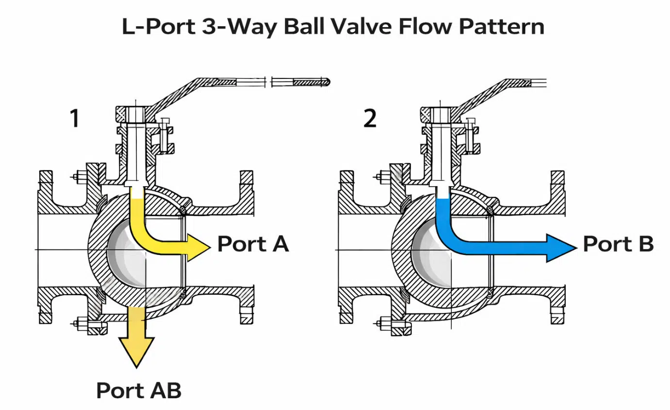
The T-bore can connect all three ports at once in certain handle positions — useful for mixing flows or systems needing a “bypass” position where oil returns to tank through the third port. Less common in high-pressure hydraulic circuits.
The 3/4″ NPT, 5,145 PSI 3-way ball valve occupies a specific niche: medium-flow, high-pressure manual diversion. One pressure source, two destinations, an operator who switches between them without powering down.
NPT threads seal by wedging — the taper compresses as you tighten. Use PTFE tape or anaerobic pipe sealant on every connection. Don’t over-torque: NPT fittings can crack valve bodies, especially near the ball bore where walls are thinnest. Many of the leak complaints we handle trace back to an over-torqued NPT joint that cracked the body — not a seat failure. It’s a surprisingly common mistake, and the crack often doesn’t show up until the system is pressurized.
Orientation matters. The common port (receiving pump pressure) must face the inlet — on most L-port 3-way ball valves, that’s the center port. Verify against the manufacturer’s flow diagram before installation. Connecting pressure to the wrong port reverses the selection logic and can dead-head the pump.
Secure the body to a bracket using the mounting holes. Pressurized hoses exert torque on fittings, and an unsecured valve body can rotate over time, loosening connections. Ball valves tolerate any physical orientation (horizontal, vertical, inverted), unlike some spool-type valve designs that depend on gravity for spring return.
High pressure ball valves are mechanically simple — no springs to fatigue, no solenoid coils to burn out. The wear items are the ball seats (POM) and stem O-rings (NBR).
Cycle the valve at least monthly if it sits in one position during normal operation. Static ball valves develop deposits at the ball-seat contact surface, increasing breakaway torque. In severe cases, the ball seizes — a preventable failure.
Contamination is the primary threat. Particles lodge between ball and seat, scoring both surfaces and creating a leak path. Maintaining clean fluid and proper pressure limits protects ball valves the same way it protects every other circuit component.
Confirm seal material compatibility before installation. Standard NBR seals work with mineral-based hydraulic oil. Systems running phosphate ester, water glycol, or biodegradable fluid require FKM (Viton) or PTFE seals — the same compatibility considerations that apply when selecting seals for hydraulic cylinders in the same circuit. If you’re unsure about your fluid type, check with your oil supplier before ordering — a seal swap after installation costs more time than getting it right up front.
Port size determines flow capacity. As a general guideline, a 3/4″ NPT ball valve typically handles roughly 15–25 GPM depending on internal bore diameter, passage geometry, and acceptable pressure drop. These numbers vary between manufacturers — always check the specific valve’s flow data or Cv rating when available. If your pump delivers significantly more than that range, the valve becomes a restriction — oil velocity increases, pressure drop rises, and the fluid generates heat instead of doing work.
For systems under 10 GPM, 1/2″ NPT is usually more appropriate. Above 30 GPM, step up to 1″ NPT. The widely cited industry guideline is to keep fluid velocity through the bore below roughly 20 feet per second to prevent seat erosion and excessive noise — though the acceptable limit depends on valve construction and fluid properties. Consult the manufacturer’s sizing recommendation for the specific model in your circuit.
It means the valve has three ports instead of two. A 3-way ball valve can route flow between different port combinations depending on handle position. L-port configurations select between two paths; T-port configurations can connect all three ports simultaneously. This replaces the need for multiple 2-way valves and tee fittings in hydraulic circuits.
On most L-port 3-way ball valves, the common port — the one that receives pump pressure — is the center port. It is typically marked on the valve body with an arrow, a “P” stamp, or identified in the manufacturer’s flow diagram. Never guess: connecting pressure to the wrong port reverses the diverter logic and can dead-head the pump. If the body markings are unclear, contact the manufacturer or check the product datasheet before installation.
No. The working pressure rating is the maximum continuous operating pressure. Exceeding it — even briefly during pressure spikes — risks seal failure, ball seat deformation, or body cracking. If your system can spike above 5,145 PSI, choose a valve rated for the maximum possible pressure including transients, not just the nominal working pressure.
Yes. NPT threads are tapered and seal by mechanical interference, but they cannot eliminate all micro-gaps without sealant. Use PTFE tape (at least 3–4 wraps in the thread direction) or anaerobic pipe sealant on every NPT connection. Avoid over-tightening — manufacturer torque recommendations vary by fitting size, but as a rough reference, most 3/4″ NPT fittings reach a seal within a few turns past hand-tight. Always follow the valve manufacturer’s installation guide for specific torque values.
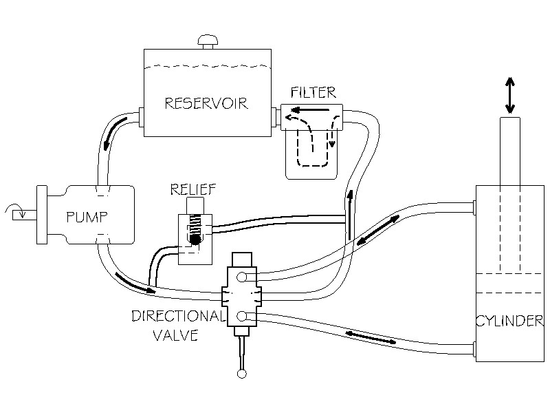
An L-port 3-way ball valve can select which cylinder receives flow, but it only controls one line — typically the pressure supply. For full directional control of two double-acting cylinders, you still need a directional control valve downstream of the 3-way ball valve to manage extend/retract. The ball valve selects which circuit is active; the DCV controls how the active cylinder moves. This is a common setup on log splitters and compact equipment with shared pumps.