
Most technicians notice cavitation after it's already done real damage. They hear a high-pitched whine from the pump, assume it's wear, and keep the machine running. A few days later the filter shows metallic debris, the pump runs hotter, and cylinders start drifting under load. At that point, the discussion shifts from prevention to teardown, flushing, and downtime that didn't need to happen.
Cavitation deserves far more attention in routine maintenance planning than it typically receives. It doesn't always show up as a sudden failure. More often it starts as a fluid supply problem: oil too viscous for the ambient temperature, a partially blocked suction path, a collapsed hose liner, a clogged breather cap, or a reservoir level that has dropped just low enough to introduce air. The pump keeps turning, but the inlet side is no longer feeding it a continuous, air-free column of oil. Once that condition exists, erosion has already begun.
Cavitation is the formation and violent collapse of vapor cavities inside hydraulic fluid. It happens when local pressure at or near the pump inlet drops below the fluid's vapor pressure. The pump is demanding oil faster than the suction path can deliver it. The oil column breaks, microscopic vapor pockets form, and when those pockets reach a zone where pressure recovers — typically inside the pump housing — they implode against the nearest metal surface.
The collapse is what causes the damage. Each implosion creates a micro-jet of fluid striking at pressures estimated between 1,000 and 10,000 bar across a tiny contact area. A single event does nothing visible. Thousands of events per second, sustained over hours or days, pit and erode port plates, gear teeth, vane tips, piston shoes, and housing bores. This is why a cavitating pump can seem to run fine for a while before performance drops off sharply — the erosion is cumulative.
Figure 1 — The three stages of cavitation: vapor pocket formation at low pressure, transport into the pump housing, and violent implosion against metal surfaces.
This process also explains why cavitation gets misdiagnosed so often. Operators report noise. Maintenance logs reduced efficiency. Someone adjusts pressure settings, swaps a valve, or questions the pump brand. Meanwhile the actual fault — a suction-side restriction — persists through every shift change.
Cavitation almost never stays contained to one component. Once eroded metal enters the fluid stream, the contamination spreads downstream. Valves start sticking or leaking. Clearances in motors and actuators wear at an accelerated rate. Operating temperature climbs because internal leakage increases. A problem that started as insufficient inlet feed can escalate into a system-wide repair involving far more than one rotating group.
We have documented this pattern repeatedly in field service: a machine comes in for "weak hydraulics," but post-mortem analysis reveals cavitation as the initial cause, followed by particle contamination, and then accelerated wear across valves, motors, and cylinders. By the time someone cuts open the filter element and finds metal, the pump is no longer the only component at risk.
A steady, high-pitched whine is one of the earliest detectable symptoms. It usually indicates suction starvation — not a pressure-side calibration problem. If the pitch changes with temperature shifts or varies as load fluctuates, focus on inlet conditions before replacing parts.
A rattling, growling, or "marbles-in-a-can" sound typically signals more aggressive implosion activity. At this stage, the question isn't "what is that noise?" — it's "how many hours has this pump already been running in this condition?" Continued operation under these conditions accelerates damage rapidly.
Metallic debris on the filter element confirms that erosion has progressed beyond noise into active material loss. You are now dealing with contamination in the fluid stream, and the damage has almost certainly extended beyond the pump itself.
Heat, sluggish response, and erratic cylinder movement often coincide with the noise symptoms. Cavitation degrades inlet fill quality and physically damages internal surfaces, but it also destabilizes flow consistency throughout the circuit. When several of these symptoms appear together, it's worth reviewing common noise and vibration patterns before assuming a single isolated fault.
Poor suction plumbing remains the number-one cause. Long suction lines, excessive bends, undersized hose bore, restrictive fittings, partially closed shutoff valves, and neglected strainers all increase the pressure drop before oil reaches the pump. The pump doesn't differentiate between a design deficiency and a maintenance oversight — the starvation result is identical.
Inlet Vacuum Thresholds — Know Your Numbers
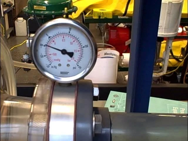
Most hydraulic pump manufacturers specify a maximum allowable vacuum at the pump inlet, typically in the range of -0.2 to -0.3 bar (6 to 8.9 inHg). Beyond -0.3 bar, the risk of vapor pocket formation increases rapidly in standard mineral oils. For pumps with a flooded inlet (reservoir above pump centerline), target vacuum should stay below -0.08 bar (2.4 inHg) during normal operation. Always verify the OEM datasheet for your specific pump — axial piston pumps are generally less tolerant than gear pumps.
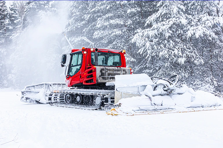
Fluid viscosity is a close second, especially during cold starts. A pump can be mechanically perfect and still cavitate if the oil is too thick for the suction path to keep pace with pump demand. Cold ambient conditions catch operators off guard because the oil still "looks normal" — but viscosity at 0°C can be five to eight times higher than at normal operating temperature. Industry case studies consistently show that hydraulic failures during the first 10 minutes of operation in sub-zero conditions are disproportionately linked to inlet starvation, not to mechanical defects. The oil doesn't need to freeze to damage the pump; it only needs to move too slowly through the suction line.
Pro Tip — Cold Start Protection
If your machine operates in ambient temperatures below 5°C, consider switching from ISO VG 46 to ISO VG 32 for winter months, or use a multi-grade fluid (e.g., Mobil DTE 10 Excel 32 or Shell Tellus S3 V 32) with a higher viscosity index. Always verify that the fluid maintains adequate film strength at maximum operating temperature — cold-start protection should never come at the cost of hot-running lubrication.
Low reservoir level also contributes, as does restricted reservoir breathing. If the tank cannot admit air fast enough as oil is drawn toward the pump, a partial vacuum develops inside the reservoir itself. A fouled or undersized breather cap can create the same starvation pattern that most technicians associate with pump failure rather than tank ventilation.
There is also a less obvious but equally destructive cause: attempting to compensate for the symptom instead of correcting the supply condition. Operators who notice weak output sometimes raise relief valve settings, dead-head actuators, or cycle the machine harder. This response drives the pump even further into starvation and turns a marginal suction problem into an expensive one.
| Ambient Temp. Range | Recommended ISO VG | Typical Viscosity @ 40°C | Cold-Start Consideration |
|---|---|---|---|
| -25°C to +10°C | VG 15 or VG 22 | 15–22 mm²/s | Essential in arctic / extreme cold. Confirm hot-running film strength. |
| -10°C to +25°C | VG 32 | 32 mm²/s | Best general choice for cold-climate mobile equipment. |
| +5°C to +40°C | VG 46 | 46 mm²/s | Industry default. May cavitate at startup below 0°C. |
| +15°C to +50°C | VG 68 | 68 mm²/s | Hot climates or systems with high internal leakage. Poor cold flow. |
| +25°C to +55°C+ | VG 100 | 100 mm²/s | Foundry / steel mill environments only. Never for mobile cold starts. |
| Wide-range / seasonal | Multi-grade (HV type) | Varies (VI > 150) | High viscosity index fluids cover wider temp. bands. Preferred for 4-season mobile. |
Note: Always cross-reference with the pump manufacturer's minimum and maximum viscosity limits (typically 10–1,000 mm²/s for piston pumps; optimal range is usually 16–36 mm²/s).
This sequence is straightforward, but it prevents one of the most expensive recurring mistakes in hydraulic maintenance: replacing a pump before anyone checked why the inlet was starving it.
If the system is also producing weak output or low pressure, don't diagnose cavitation in isolation. Use a structured low-pressure troubleshooting procedure to separate true pump damage from pressure losses caused elsewhere in the circuit.
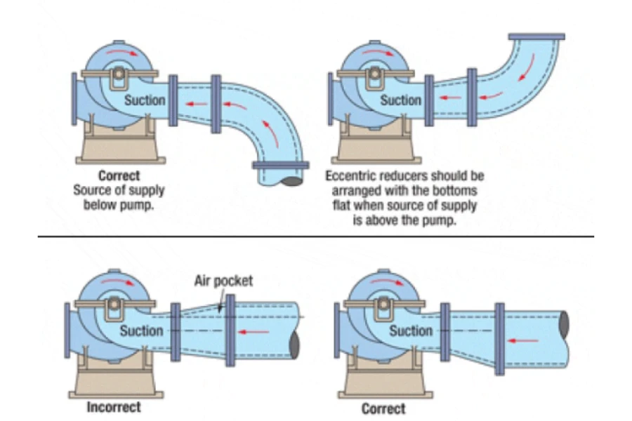
Effective prevention is mostly unglamorous maintenance discipline. It starts with keeping the suction path as short, smooth, and unrestricted as possible. Size the hose for actual peak flow — not nominal ratings. Place the reservoir above or level with the pump inlet wherever the installation allows. Use a breather that can actually keep up with flow demand. And select a fluid grade matched to the machine's real operating temperature range, including the coldest mornings — not just a midsummer afternoon when everything runs fine.
Warm-up practice matters more than many operators acknowledge. Running the system at low load for two to five minutes at the start of each shift allows the fluid to reach a pumpable viscosity before the hydraulics face full demand. Cold starts are especially punishing on axial piston pumps — once pitting begins on the valve plate or barrel kidney ports, it cannot be reversed.
Pro Tip — Warm-Up Sequence for Mobile Equipment
Start the engine at low idle. Allow 60–90 seconds before activating any hydraulic functions. Then cycle each function (boom, arm, bucket, swing) through its full range at minimum speed, with no load, for at least 2 full cycles. Monitor for noise changes — if whining decreases within 3–5 minutes, the system is reaching acceptable viscosity. If it doesn't, the fluid grade or suction path needs attention.
Reservoir discipline matters as well. Keep the oil at the correct level. Watch for persistent foam, which indicates air is being entrained through the return circuit. Don't let aggressive return-line conditions churn the tank into an aeration source. If the machine repeatedly develops chatter, unstable pressure, or excessive heat at the relief valve, review your relief valve setup — some pressure-side symptoms can distract a maintenance team from the suction-side fault that triggered the whole chain.
Critical Warning — Do Not Raise Relief Pressure to Compensate for Weak Output
Increasing the relief valve setting when the pump is already starved does not restore flow — it forces the pump to work harder with less oil, dramatically accelerating cavitation erosion. If output feels weak and the pump is noisy, the correct response is to inspect the suction side, not to raise pressure. A higher relief setting on a starved pump will shorten its remaining life from weeks to days.
✕ Do not assume a new pump fixes the problem. A new pump installed into the same bad suction conditions is simply a fresh component entering the same failure mode. Correct the inlet restriction first.
✕ Do not keep running "until the next scheduled shutdown" when cavitation noise is already present. The damage is cumulative, and the contamination it generates migrates through the entire circuit.
✕ Do not treat every abnormal sound the same way. Cavitation, aeration, mechanical wear, and relief valve instability can all produce noise — but they require different corrective actions. Diagnosis must come before parts ordering.
If you've confirmed pitting on internal surfaces, metal in the filter, or obvious pump distress, stop thinking in single-component terms. Assess how far the contamination has traveled: inspect the filter element, check the reservoir for settled debris, and evaluate downstream components — particularly proportional valves and servo valves — for contamination-related degradation.
Decide whether you are repairing, replacing, or flushing based on contamination spread, not just pump condition. If the debris has migrated past the first filter stage, a full system flush to a target cleanliness of ISO 16/14/11 or better is usually necessary before installing any replacement components.
At that point, it may also be worth evaluating pump type and application fit rather than simply ordering "the same part again." If the system uses an axial piston design, specifications like those on this variable-displacement axial piston pump are far more useful when matched against actual operating pressure, flow demand, temperature range, and suction conditions — not selected by model number alone.
Cavitation prevention isn't about additives, alarms, or post-failure blame. It is about ensuring the pump inlet stays full, continuously fed, and stable. The oil has to reach the pump easily, at a viscosity the suction path can handle, without creating excessive vacuum or turbulence.
When maintenance teams internalize that principle, they troubleshoot more effectively. They check the reservoir before reaching for a wrench. They question the suction path before adjusting the pressure setting. They treat unusual noise as diagnostic data — not background irritation. And they prevent pump failures that would otherwise become expensive lessons repeated across every machine in the fleet.
It can continue operating if the damage is still limited, but the erosion that has already occurred doesn't reverse. Surface pitting is permanent. The real question is whether the cause was caught early enough to stop the progression before contamination and accelerated wear take over.
No. Cavitation involves vapor bubble formation and collapse driven by low local pressure. Aeration is air entering or being entrained in the fluid. Symptoms can overlap (noise, foam, erratic operation), but the root causes and corrective actions differ. Cavitation is a suction-pressure problem; aeration is an air-ingress problem.
No. Cold weather increases the risk by raising viscosity, but cavitation can occur year-round due to clogged strainers, collapsed suction hose liners, low oil level, restricted breathers, undersized plumbing, or any restriction severe enough to drop inlet pressure below the fluid's vapor pressure.
Start at the inlet side. Check reservoir level, breather condition, suction hose integrity, strainer restriction, and fluid viscosity for the current temperature — all before adjusting pressure settings or ordering replacement parts. Install an inlet vacuum gauge if you don't have one.
Because the downstream symptoms look like pump or pressure-control failures: noise, heat, unstable pressure, slow actuator response. Maintenance teams naturally focus on the visible performance loss. Unless the troubleshooting sequence traces the fault path back to the suction side first, the real cause stays hidden while unrelated parts get replaced.
Most pump manufacturers set a limit between -0.2 and -0.3 bar (6 to 8.9 inHg). Readings above -0.3 bar during loaded operation indicate a high probability of vapor pocket formation. For flooded-inlet installations, keep steady-state vacuum below -0.08 bar. Always verify against the specific pump OEM datasheet.