
Relief Valve — When Pressure Exceeds, Open the Gate to Release Oil
Hydraulic systems rely on oil pressure to operate. From the pump outlet to the actuator, the system must be sealed and pressure-resistant. However, containers have limited pressure tolerance, and exceeding the pressure limit will cause damage. There are three reasons for pressure rise in enclosed oil chambers:
First, the volume of oil entering exceeds the volume leaving. Second, the container volume is compressed; since the interior is filled with oil and sealed, the oil volume is correspondingly compressed. Third, the oil heats up. When unrestricted by the container, oil volume expands. The oil expansion coefficient is approximately 0.0007/K; with a temperature rise of 50K, volume expands by 3.5%. However, since container volume remains unchanged, pressure rises.
For the first cause, a pressure reducing valve can be installed: when outlet pressure (chamber pressure) exceeds the limit, it closes to prevent further oil flow. However, this cannot prevent pressure rise from the latter two causes. Therefore, a relief valve is needed: when chamber pressure exceeds the limit, it opens to release oil and limit pressure.
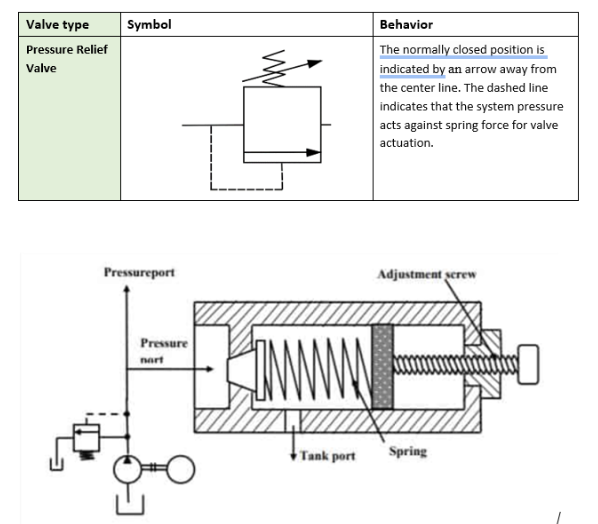
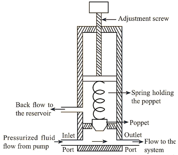
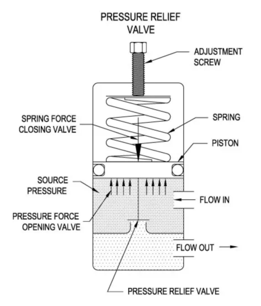
Relief valves generally have two ports (inlet and outlet): the outlet is usually connected to the tank (low steady-state pressure); the spring chamber is usually connected to the outlet (some connect to the tank through an independent control port). The valve spool is subject to pressures from the inlet, outlet, and spring chamber, as well as spring force. When outlet and spring chamber pressures are negligible, if inlet pressure exceeds the preset spring force, the spool lifts and opens the oil release passage, limiting inlet pressure through oil release.
Since relief valves can prevent pressure from exceeding limits regardless of the cause, almost all hydraulic systems are equipped with relief valves, making them an indispensable valve type.
Hydraulic systems are divided by the directional valve: the pump side is called the primary (main) stage; the hydraulic cylinder side is called the secondary stage.
The core mission is pressure limiting: continuously limiting pump port or other location pressure to desired levels. In this condition, the relief valve remains open with continuous oil flow.
For example, in throttle speed control circuits, the flow valve only adjusts hydraulic resistance; the relief valve serves as backup, releasing excess flow and maintaining constant pressure, supporting the flow valve in controlling hydraulic cylinder flow and speed.
Since the pump has continuous flow, it must be ensured that full pump flow can pass through the relief valve and that pressure does not exceed the set value by too much (small pressure variation).
Characteristics of this condition: continuous flow, requiring erosion-resistant valve opening; normally open, with lower requirements for valve response speed.
Relief valves can be used in return oil lines to create back pressure: at low pressure (oil mixed with air), oil has low elastic modulus; back pressure can increase elastic modulus, causing smaller oil volume changes when load pressure varies, improving motion stability.
Limits pump port pressure: prevents the prime mover (electric motor, diesel engine, etc.) driving the pump from stalling due to excessive pump load.
Bypass throttle circuit: the maximum pressure when full pump flow is discharged through the bypass throttle port (maximum pump port pressure) must not exceed the pump’s allowable pressure; the relief valve only serves as safety protection against accidents.
Constant pressure pump circuit: pump port pressure is maintained at set value by the displacement mechanism; the relief valve only serves as safety protection, with its set pressure approximately 2-3MPa higher than this set value.
Characteristics of this condition: relief valve normally closed, opening briefly only when overpressure occurs; low flow rate, but requires fast response (opening/closing); frequent opening/closing requires impact-resistant spool and body.
Primary stage relief valves protect the pump; secondary stage relief valves protect the hydraulic cylinder. Their opening pressure setting should be higher than the primary stage relief valve.
For example: when hydraulic cylinders experience excessive load forces, or when hydraulic cylinders with large inertia loads accelerate/decelerate producing excessive inertial forces, the relief valve opens to limit pressure, preventing damage to hydraulic cylinders or connecting components; during rapid swinging, pressure in some hydraulic cylinders can reach relatively high values. This application requires fast opening and closing of relief valves.
When the hydraulic cylinder piston reaches end of stroke and ports are sealed by the directional valve, oil temperature rise and expansion will cause pressure rise; the relief valve opens to release oil, protecting the hydraulic cylinder from high-pressure damage.
Since temperature rise is slow and oil expansion flow is small, thermal relief valves only require small flow capacity.
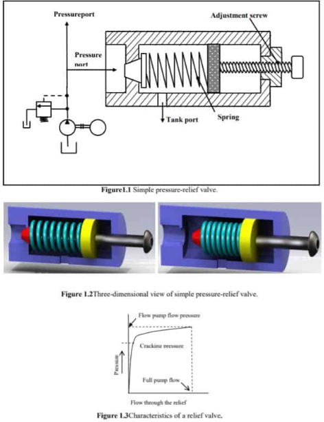
Relief valve steady-state performance is mainly reflected through flow-pressure characteristics.
Cracking pressure: set by spring preload force or proportional solenoid electromagnetic force; this is the theoretical pressure at “about to open but not yet open”; actual opening confirmation requires flow.
Control pressure: the inlet pressure actually limited by the relief valve (customary term).
Ideal relief valve: closes when inlet pressure is less than cracking pressure; opens when greater than or equal to cracking pressure, maintaining constant cracking pressure regardless of flow changes.
Actual relief valve: control pressure varies with flow rate.
Pressure override: at a certain flow rate, the difference between control pressure and cracking pressure (also called static pressure overshoot).
Pressure-flow ratio: used to compare pressure override between different valves; formula is “pressure change divided by flow change.”
Pump flow has pulsations, which cause relief valve inlet pressure fluctuations; greater pressure override means larger pressure fluctuations.
Generally, large pressure override is undesirable (causes premature relief, resulting in flow and energy losses and noise); but in some scenarios (such as wanting lift to slow as load approaches maximum), large pressure override is desired.
Cracking pressure is a theoretical term (difficult to measure); in practice, the control pressure at a predetermined flow rate is used as the set pressure.
Different manufacturers have no unified standard for set flow rate; system designers must determine set pressure based on their system’s operating flow and maximum control pressure; confirm set flow rate with supplier when ordering.
Mainly spring force and flow force.
① Spring Force
When valve is closed (inlet pressure less than cracking pressure), spool displacement is 0.
After valve opens, increased flow → increased spool displacement → increased spring compression → increased spring force → higher control pressure.
Higher spring stiffness results in more significant pressure override; higher cracking pressure results in smaller spring force effect (at high pressure, flow increment causes smaller spool displacement increment, thus smaller spring force increment).
② Flow Force
Increased flow → increased flow force; flow force direction is same as spring force (tends to close valve), increasing pressure override.
Some relief valves reduce pressure override through structural optimization (using flow recoil force).
Note: If the characteristic curve shows a declining pattern, system instability may result.
When valve opening increases to a certain extent, it becomes a fixed orifice (valve fully open); the flow-pressure characteristic at this point is called full flow characteristic: there is a minimum control pressure for corresponding flow, and spring adjustment cannot reduce control pressure below this value; as flow increases, control pressure rises, and the relief valve loses its pressure regulation characteristic.
Some valves cannot operate stably at very low spring preload, thus having minimum operating pressure limits.
Some product catalogs provide “nominal flow (rated flow),” but this is only for reference with relief valves: after opening, higher pressure means higher flow; there is no fixed allowable flow.
Different manufacturers define nominal flow differently: some define nominal flow as approximately 1 times the full flow at minimum adjustment pressure, while also providing pressure-flow curves for higher flows; some only provide pressure-flow curves without marking nominal flow.
Due to inconsistent definitions, users must select valves based on their operating flow and tolerable pressure override: if selecting a valve with nominal flow much larger than actual flow, pressure override is usually small, but spool volume is larger, transient response is worse, and leakage may increase.
In actual relief valve pressure-flow measurement curves, the falling flow curve does not coincide with the rising flow curve; this phenomenon is called “hysteresis.” Causes include: when flow decreases, flow force decreases, and reduced pressure can still maintain spool opening; friction exists between sliding poppet spool and valve body; some valves add O-rings, using friction to reduce spool vibration.
These factors impede spool closing, causing control pressure to decrease.
The measure of hysteresis is the ratio of closing pressure to cracking pressure (approximately 75%-90%; higher ratio is better); this performance is also called “cracking-closing characteristic.”
During flow fluctuations, the spool cannot respond promptly due to hysteresis, causing larger pressure fluctuations. Therefore, when used as a pressure regulating valve, both small pressure override and small hysteresis are usually desired.
However, when used as a safety valve, larger hysteresis may be an advantage: normally remains closed, opens with large relief flow, and only closes when system pressure drops significantly below set pressure.
In practice, relief valve flow-pressure characteristics generally exhibit hysteresis, but product catalog performance curves often deliberately minimize hysteresis.
Relief valve transient performance can be evaluated from perspectives of overshoot, response time, and settling time.
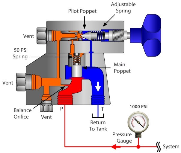
Standard relief valve: when system pressure has not reached cracking pressure, the spool remains stationary; when pressure exceeds spring preload force, the spool needs time to move to the corresponding position, during which system pressure continues to rise, forming “overshoot.” Pilot-operated relief valve overshoot is higher than direct-acting type.
Alternating loads are more harmful to material durability than static loads; if load variation amplitude is low, materials can withstand greater loads. Therefore, reducing pressure overshoot is crucial for improving system component durability.
Overshoot is determined by both system pressure rise rate and relief valve response time: overshoot is approximately the product of these two (higher pressure rise rate and longer response time mean greater overshoot).
System pressure rise rate formula: Pressure rise rate = (Input flow × Oil elastic modulus) / System volume.
Methods to reduce pressure rise rate: increase chamber volume, use hoses or accumulators.
Relief valve response time is generally 2-20ms; if calculated using longer times, system line pressure peaks will exceed cracking pressure significantly, representing considerable impact on pumps, valves, and lines.
Factors affecting response time: spool and spring inertia, friction, opening, damping added to maintain stable opening, etc. Manufacturers often shorten response time by reducing internal damping and spool opening overlap, but valve stability may correspondingly decrease.
Theoretically, poppet valves respond faster than spool valves, and direct-acting types respond faster than pilot-operated types.
Related standards provide test methods, but some international manufacturers do not follow them (some conditions are difficult to achieve, some definitions are questionable).
To reduce test system influence on results, test system pressure rise rate must be much higher than tested valve response speed; standards require test system speed to be 10 times that of tested valve, but this requirement is difficult to achieve.
System pressure rise rate derivation formula: System pressure rise rate = (Input flow × Oil elastic modulus) / System volume; therefore test system volume must be very small, which is difficult to achieve in practice.
Compromise method: place tested valve, safety valve, and bypass valve as close to pump outlet as possible, shorten bypass valve closing time; compare performance of different valves on the same test system.
Testing on user’s own system with fast-response pressure sensors best reflects actual conditions.
Related standards define indicators, but response time definition is questionable: before inlet pressure reaches cracking pressure, relief valve does not open; this period only reflects test system transient response, unrelated to relief valve; afterward, pressure rise rate decreases because relief valve has opened.
Considering relief valve pressure override: before test system pressure reaches cracking pressure point, relief valve is completely closed; due to spool inertia, relief passage must reach a certain point before fully opening; this period is tested valve response time, but this point is difficult to determine in practice.
Some manufacturers provide “average response time” without specifying test standards and conditions.
Response performance can be evaluated by combining overshoot with system pressure rise rate (overshoot is the ultimate purpose of relief valve; if test bench cannot measure overshoot, system pressure rise rate is too low).
For manufacturers: since valve application system is unknown, universal indicators must be provided, hence definition ambiguity exists.
For users: once valve application system is clear, testing is simpler (can build test system matching “volume-pressure rise rate,” use actual directional valve for loading, obtain actual overshoot and study countermeasures).
Relief valve opening is usually accompanied by considerable noise: high-pressure oil rushes out at high speed through narrow gaps, accompanied by turbulence and cavitation; noise type (sharp/dull) is related to outlet passage shape.
Noise acceptability depends on scenario: when used as normally open pressure regulating valve, lower noise is preferred; when used as safety valve (with alarm function), sharp noise may be an advantage.
Some relief valves become unstable after opening (excessive noise); causes include:
Pressure regulation spring too soft, damping too high: spool inertia overshoot → excessive opening → pressure drops suddenly → spool returns → opening decreases → pressure rises again, cycling repeatedly.
Oil temperature too high: oil viscosity decreases, damping effect weakens, affecting stability.
Spring chamber contains air: poor damping effect, prone to instability (pre-filling with oil can increase damping).
Spool inertia and spring stiffness determine valve natural frequency; if close to system actuator/other valve natural frequencies, resonance tends to occur and should be avoided.
Instability is unacceptable performance and should be replaced free by supplier; manufacturers must conduct extensive testing across full pressure, flow, and oil temperature ranges for different operating condition combinations.
In some scenarios, “enhanced damping type” valves can be selected to improve stability.
When selecting relief valves, the following indicators should also be noted:
Refers to the range during adjustment where control pressure (inlet pressure) can rise and fall smoothly without sudden jumps or large fluctuations.
Pressure adjustment ranges vary significantly among different suppliers.
Advantages and disadvantages of valves with large adjustment range:
Advantages: few varieties can cover wide requirements.
Disadvantages: requires longer pressure adjustment spring → larger dimensions; softer spring → larger pressure override → difficult to adjust precisely.
The adjustment range given by suppliers is usually for “a certain flow rate with outlet pressure near zero”; if user’s actual flow/outlet pressure differs, this range may not apply.
Some product specifications state: maximum set pressure can reach a high value, inlet maximum short-term operating pressure allows this value, but allowable continuous operating pressure is only a lower value.
Scenario differences:
As safety valve: inlet high pressure is usually brief (pressure drops after oil release), so can be set to higher values.
As pressure regulating valve: inlet high pressure is continuous, so set pressure must be below allowable continuous operating pressure.
Note outlet allowable pressure: no problem when outlet connects directly to tank; when used in secondary stage, high pressure may occur at outlet during valve switching.
Two situations:
When relief passage is open and inlet pressure is higher than closing pressure: not closed due to hysteresis, this is “normal” leakage; at low temperature, high oil viscosity, soft spring, and low set pressure, leakage is higher, making closure more difficult.
When inlet pressure is lower than closing pressure: relief passage should be closed; “internal leakage at certain percentage of cracking pressure” in product catalogs refers to this situation; leakage is unavoidable with spool-type valve cores (most pilot-operated main valves); select poppet valves if zero leakage is desired.
Leakage tolerance depends on scenario:
On pump side (protecting pump): pump supplies continuous flow, slight leakage is usually tolerable.
On hydraulic cylinder side (as safety valve): if load must remain stationary for extended periods, leakage rate is a critical performance indicator.
At relief valve opening, high-pressure oil pressure energy converts to kinetic energy, ultimately becoming heat energy; accompanied by severe cavitation (local temperatures can be very high).
When relief valve frequently opens and closes, spool rapidly impacts seat; opening material’s cavitation resistance and impact resistance are key factors determining working durability. Relief valves are generally surface-hardened now; some valves reduce cavitation by improving inlet/outlet passage shape.
At current technology levels, some products can achieve high cycle counts, with precision products achieving even more:
As rarely-opening safety valve: lifespan is usually not a major concern.
As continuously-open pressure regulating valve: durability is important (testing is time-consuming and expensive; suppliers generally do not provide data in catalogs; designers must extrapolate from other application experience).
Pilot-operated main valve spools often have small pressure differential orifices that are easily blocked, thus contamination resistance is worse than direct-acting type. Safety standards require: at least one direct-acting relief valve in the main system.
With relief valve as safety valve, preventing unauthorized adjustment is extremely important; manufacturers provide various corresponding protection measures.
With hydraulic technology development, relief valves have evolved into many variants, classifiable from different perspectives:
Ball valve type: simple structure, low cost, but only suitable for small flow.
Poppet valve type: can handle larger flow, low leakage, fast response, long life, most widely applied.
Spool valve type: can handle even larger flow, but smaller adjustment range.
Differential type: avoids using heavy springs at high pressure.
Sliding poppet type: can handle the largest flow (virtually no upper limit), widely used in cartridge-type structures.
Direct-acting type: faster response, smaller overshoot, low leakage, more contamination resistant, but larger pressure override (control pressure fluctuates more with flow); suitable for safety valves.
Pilot-operated type: smaller pressure override, suitable for applications requiring more precise control pressure, allows larger working flow, but slightly slower response; suitable for use as pressure regulating valve in fixed displacement pump throttle circuits.
Soft relief type: can open relief prematurely before inlet pressure reaches set value, avoiding overshoot.
Standard type.
Pressure fuse type: once opened, does not close until inlet pressure drops to zero; not suitable for circuits requiring load holding.
With reverse check valve type: standard relief valves do not allow reverse flow; this type enables reverse flow.
Bidirectional type: in closed circuits, prevents excessive pressure on either side of actuator.
Externally controlled type: controlled externally from outside the valve (e.g., pilot-controlled), including various opening types of relief valves.
From connection perspective: standard type has two ports; three-port and four-port relief valves are all externally controllable types.