
The cylinder hydraulic system represents one of the most fundamental and versatile components in modern fluid power technology. As an essential actuator in hydraulic systems, hydraulic cylinders serve the critical function of converting hydraulic energy into mechanical energy, enabling countless industrial applications from construction equipment to manufacturing machinery.
This comprehensive analysis explores the working principles, diverse classifications, and distinctive characteristics of hydraulic cylinders, providing engineers and technicians with essential knowledge for selecting and implementing these crucial components in various applications.
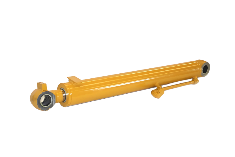
Hydraulic cylinders provide precise force and motion control in industrial applications
Hydraulic cylinders operate on fundamental fluid power principles, converting hydraulic energy into mechanical motion through precise engineering.
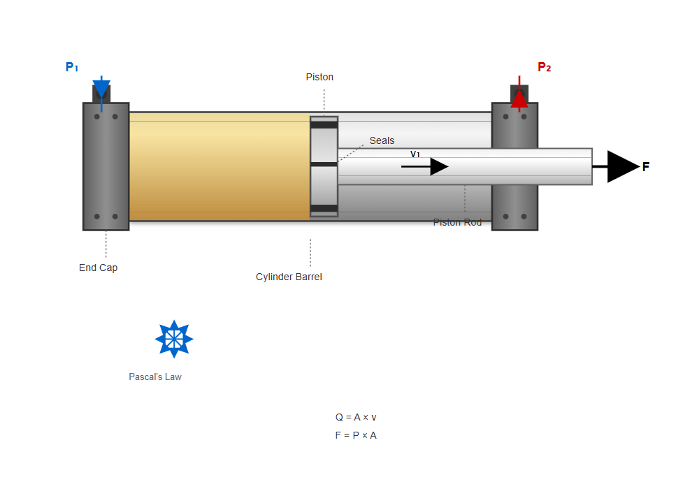
The cylinder hydraulic mechanism operates on Pascal's law, which states that pressure applied to a confined fluid is transmitted equally in all directions. In practical terms, a hydraulic cylinder consists of several key components: the cylinder barrel, piston, piston rod, end caps, and sealing elements.
These components work in harmony to transform the input parameters of fluid flow rate and pressure into output parameters of linear velocity and force.
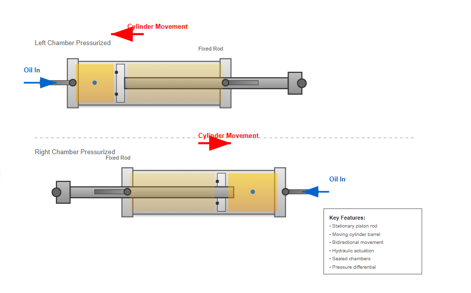
When hydraulic fluid enters the cylinder chamber, it exerts pressure on the piston surface. If the cylinder barrel remains fixed and continuous hydraulic oil flows into the left chamber, the pressure must overcome all loads acting on the piston rod. Once this threshold is exceeded, the piston moves continuously to the right at velocity v₁, causing the piston rod to perform work on external systems. Conversely, when hydraulic oil enters the right chamber, the piston moves leftward at velocity v₂, similarly performing work through the piston rod. This reciprocating motion forms the basis of hydraulic cylinder operation.
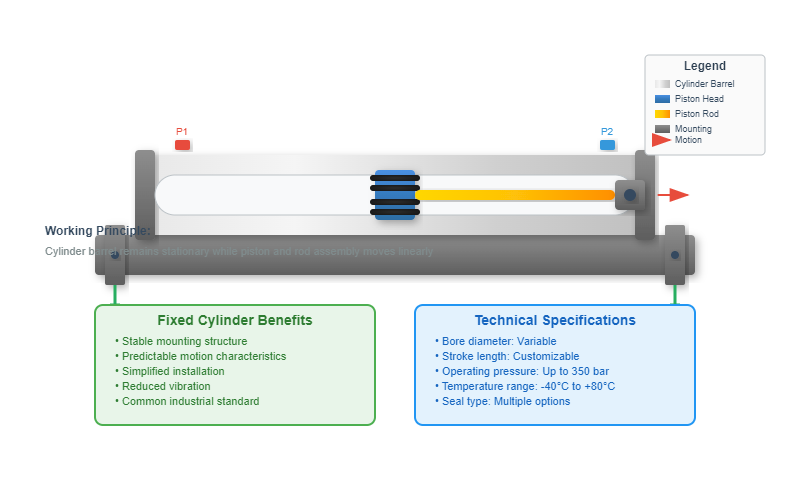
In the fixed cylinder configuration, the cylinder barrel remains stationary while the piston and rod assembly moves. This represents the most common arrangement in industrial applications, providing stable mounting and predictable motion characteristics.
In the fixed piston rod configuration, the piston rod remains stationary while the cylinder barrel moves. When hydraulic oil enters the left chamber, the cylinder barrel moves leftward. Conversely, oil supply to the right chamber causes rightward cylinder movement.
The energy conversion within a cylinder hydraulic system involves transforming hydraulic energy into mechanical energy. The hydraulic oil supplied to the cylinder must possess both pressure (p) and flow rate (q).
The pressure component overcomes the resistance forces or loads, while the flow rate determines the movement velocity. This input of hydraulic energy, characterized by pressure p and flow rate q, converts into mechanical energy output, manifested as force F and velocity v acting on the load.
These four parameters—input pressure and flow rate, output force and velocity—constitute the primary performance indicators of hydraulic cylinders.
Hydraulic cylinders are classified by various criteria including oil supply direction, structural form, piston rod configuration, and specialized purposes.
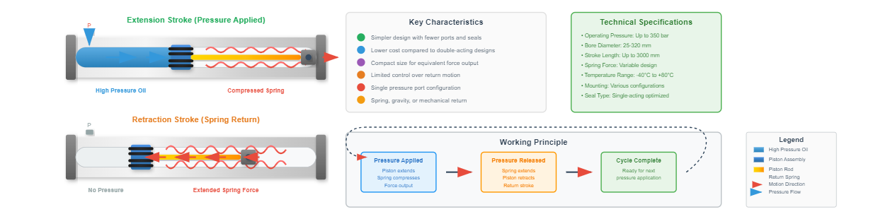
Single-acting cylinders receive high-pressure oil on only one side, relying on external forces such as springs, gravity, or mechanical means for return stroke.
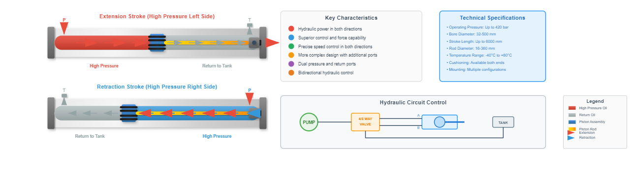
Double-acting cylinders receive hydraulic oil on both sides, enabling hydraulic power control for both extension and retraction strokes.
A closer examination of specific cylinder types reveals their unique characteristics and optimal applications.
Single-acting cylinders in the cylinder hydraulic domain operate through hydraulic pressure in one direction only. The piston cylinder variant features a conventional piston assembly, while the plunger cylinder employs a solid plunger design.
Telescopic single-acting cylinders incorporate multiple interconnected pistons with variable stroke capabilities, requiring external force for retraction. These cylinders find extensive application in lifting equipment, dump trucks, and agricultural machinery where gravity or load weight provides the return force.
Hydraulic lifting with gravity return for bed operation
Efficient vertical lifting with spring return mechanisms
Implement positioning with mechanical return systems
Different designs optimized for specific applications while maintaining single-direction hydraulic operation
Features a piston with seals, separating the pressure chamber from the atmospheric side.
Uses a solid plunger without seals, relying on close clearance for operation.
Multi-stage design providing extended stroke from compact retracted length.
Double-acting configurations dominate modern cylinder hydraulic applications due to their versatility and control capabilities. Standard double-acting cylinders provide bidirectional hydraulic control without end-position deceleration.
Non-adjustable cushioned cylinders incorporate fixed deceleration mechanisms at stroke ends, preventing impact damage. Adjustable cushioned cylinders feature variable deceleration rates, allowing optimization for different loads and speeds.
Differential cylinders exploit significant area differences between piston sides, creating distinct force and velocity characteristics that profoundly influence system operating characteristics.
| Cylinder Type | Key Feature | Typical Application |
|---|---|---|
| Standard Double-Acting | Basic bidirectional control | Material handling |
| Non-adjustable Cushioned | Fixed end deceleration | Machine tools |
| Adjustable Cushioned | Variable deceleration rates | Automation systems |
| Differential | Area ratio effects | Presses and punches |
Pressure Port (Cap End)
High-pressure oil enters
Return Port (Rod End)
Oil exits to reservoir
Pressure Port (Rod End)
High-pressure oil enters
Return Port (Cap End)
Oil exits to reservoir
The cylinder hydraulic field continues evolving with sophisticated designs addressing specific application challenges. These advanced configurations provide solutions for specialized motion control requirements.
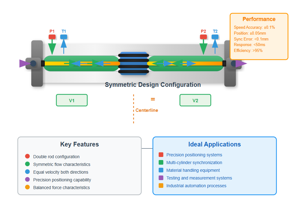
These cylinders ensure identical velocity and stroke in both directions through symmetric design, incorporating double rods or specialized porting to balance flow characteristics.
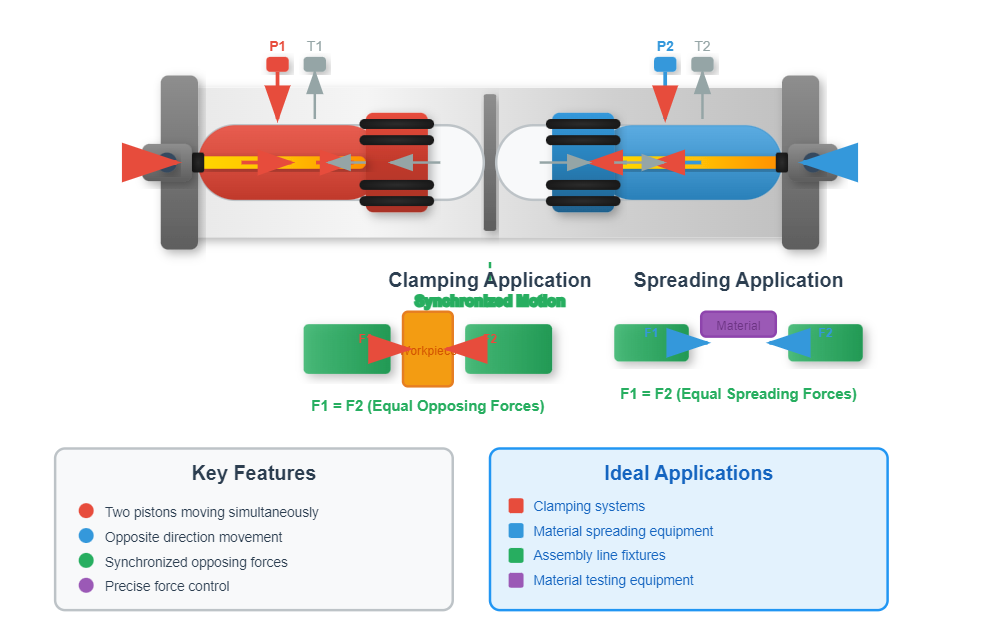
Feature two pistons moving simultaneously in opposite directions, useful in clamping and spreading applications where synchronized opposing forces are required.
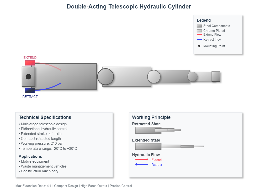
Combine multi-stage extension with bidirectional hydraulic control, maximizing stroke length while maintaining compact retracted dimensions for mobile applications.
Understanding the key performance parameters of hydraulic cylinders is essential for proper selection and application.
The force output of a cylinder hydraulic system depends on several factors. The effective piston area multiplied by the applied pressure determines the theoretical force output.
However, practical considerations including friction losses, seal drag, and side loading effects reduce actual force delivery. Single-rod cylinders exhibit different force capabilities for extension and retraction due to the rod area reducing effective piston area on one side.
This characteristic proves advantageous in applications requiring higher extension force or faster retraction speeds.
Theoretical Force
F = P × A
Where: F = Force (N), P = Pressure (Pa), A = Area (m²)
Extension Force (Single-Rod)
Fₑ = P × (πD²/4)
Where: D = Piston diameter
Retraction Force (Single-Rod)
Fᵣ = P × (π(D²-d²)/4)
Where: d = Rod diameter
• Unequal force in extension/retraction
• Better suited for push-dominant applications
• Equal force in both directions
• Ideal for balanced force applications
Cylinder hydraulic velocity directly correlates with input flow rate and effective piston area. The relationship v = Q/A (where v represents velocity, Q denotes flow rate, and A indicates effective area) governs cylinder speed.
Differential cylinders exploit area ratios to achieve rapid advance speeds during low-load conditions, automatically transitioning to high-force, low-speed operation when encountering resistance. This self-adjusting characteristic eliminates the need for complex external controls in many applications.
| Cylinder Type | Extension Velocity | Retraction Velocity |
|---|---|---|
| Single-Rod | vₑ = Qₑ / Aₑ | vᵣ = Qᵣ / Aᵣ |
| Double-Rod | vₑ = Qₑ / A | vᵣ = Qᵣ / A |
| Differential | vₑ = (Qₑ + Qᵣ) / Aₑ | vᵣ = Qᵣ / Aᵣ |
Modern cylinder hydraulic designs incorporate sophisticated cushioning systems to prevent destructive impacts at stroke ends. These mechanisms reduce velocity gradually as the piston approaches the end of its travel, minimizing stress and extending component life.
Employs precisely machined spear-and-bushing arrangements that restrict fluid flow as the piston approaches stroke limits, providing consistent deceleration characteristics.
Features needle valves or variable orifices, enabling optimization for varying loads and speeds. Allows system tuning for different operating conditions.
Utilizes progressive flow restriction, providing smooth deceleration profiles that minimize stress on cylinder components and connected machinery.
Specialized cylinder designs address unique application requirements beyond standard linear actuation needs.
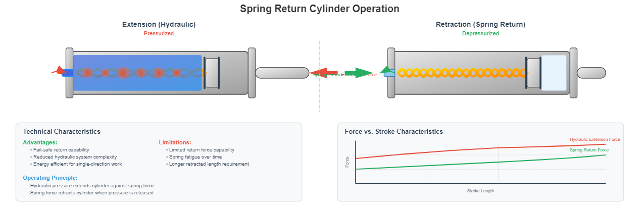
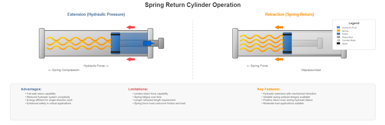
Spring return cylinders represent a hybrid approach in cylinder hydraulic design, combining hydraulic extension with mechanical retraction. The spring mechanism ensures positive return even during hydraulic system failure, enhancing safety in critical applications.
Spring force must overcome friction and load forces, limiting these cylinders to moderate load applications. Variable spring preload designs allow adjustment of return characteristics to match specific application requirements.
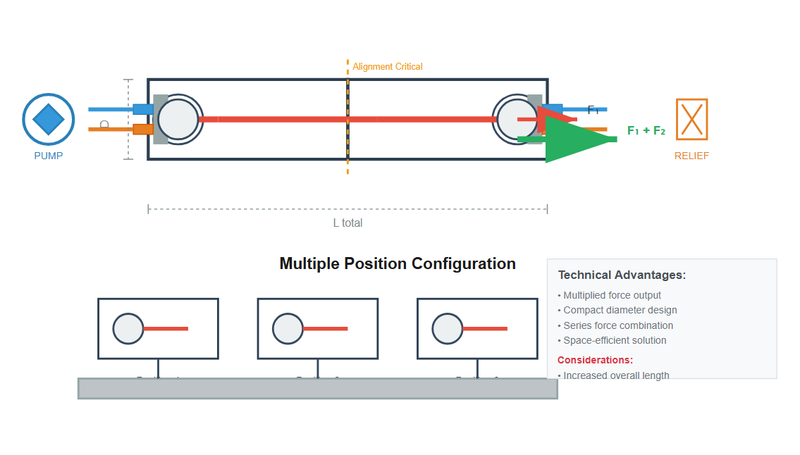
Tandem cylinder hydraulic configurations address space constraints while delivering substantial force output. By connecting multiple cylinder stages in series, these designs multiply force while maintaining relatively small diameters.
The trade-off involves increased overall length and potential alignment challenges that must be considered during installation.
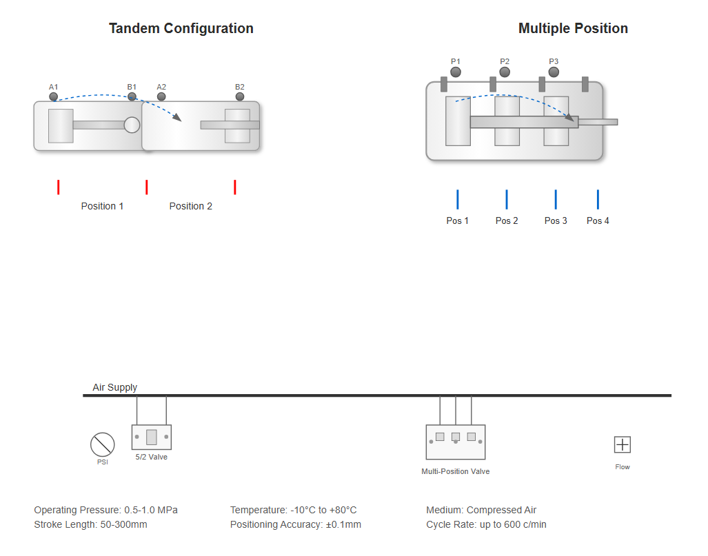
Multiple position cylinders incorporate three or more discrete positions, achieved through mechanical stops, multiple pistons, or sophisticated valve arrangements. These cylinders eliminate the need for external positioning systems in applications requiring repeatable multi-point positioning.
Intensifier cylinders exploit Pascal's law to amplify pressure within the cylinder hydraulic system. A large-diameter, low-pressure chamber drives a smaller high-pressure chamber, achieving pressure multiplication proportional to the area ratio.
This principle enables localized high-pressure generation without requiring high-pressure pumps throughout the entire system. Applications include hydraulic presses, clamping systems, and injection molding machines where brief high-pressure cycles are required.
Pressure Ratio = (Area of large piston) / (Area of small piston)
Step cylinders represent an innovative approach to discrete positioning in cylinder hydraulic applications. Multiple pistons with binary-related strokes (1:2:4:8 ratios) enable 2ⁿ distinct positions using n pistons.
Selective pressurization of different chambers achieves precise positioning without continuous feedback control. Digital cylinder technology extends this concept, incorporating electronic control and feedback systems for enhanced accuracy and repeatability.
4 pistons with binary strokes = 16 possible positions
Proper cylinder selection requires careful analysis of application requirements and operating conditions.
Selecting appropriate cylinder hydraulic components requires careful analysis of load characteristics. Static loads remain constant throughout the stroke, while dynamic loads vary with position, velocity, or time.
Inertial forces become significant in high-speed applications, potentially exceeding static load forces during acceleration and deceleration phases. Safety factors typically range from 1.5 to 3.0, depending on application criticality and load uncertainty.
Static Loads
Constant loads that do not change with time or position, including dead weight of components.
Dynamic Loads
Variable loads that change with velocity, acceleration, or position during cylinder operation.
Shock Loads
Sudden, transient loads caused by impacts, sudden stops, or rapid direction changes.
Environmental factors significantly influence cylinder hydraulic selection and design. Proper consideration of operating conditions ensures optimal performance and longevity.
Affect seal performance, fluid viscosity, and material properties. Requires specialized seals and fluids for extreme hot or cold environments.
Critical in dusty or dirty environments, necessitating robust rod wipers and sealed bearing designs to prevent premature wear.
Demand specialized materials and coatings (chrome, nickel, stainless steel) to prevent degradation from chemicals or saltwater.
Frequency, duty cycle, and cycle rate affect component wear and heat generation, influencing material and design choices.
| IP Rating | Protection Against Solids | Protection Against Liquids | Typical Application |
|---|---|---|---|
| IP65 | Complete protection against dust | Protection against low-pressure water jets | General industrial |
| IP66 | Complete protection against dust | Protection against high-pressure water jets | Washdown environments |
| IP67 | Complete protection against dust | Protection against temporary immersion | Outdoor equipment |
| IP68 | Complete protection against dust | Protection against prolonged immersion | Marine applications |
Proper mounting ensures optimal cylinder hydraulic performance and longevity. The mounting style affects load distribution, alignment, and overall system behavior during operation.
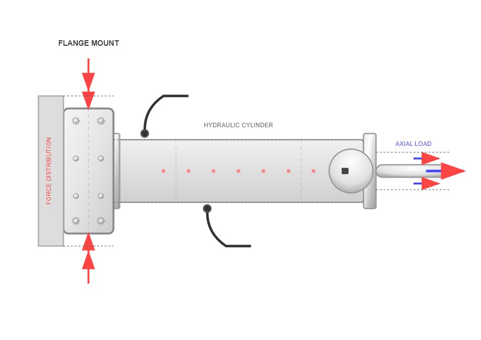
Provides rigid mounting with flange at cylinder end, distributing forces through the mounting surface. Ideal for fixed applications with axial loads.
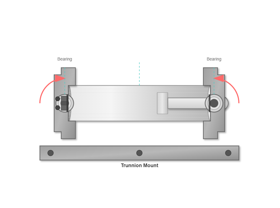
Pivoting mount with trunnion bearings, accommodating angular movement while maintaining alignment under load.
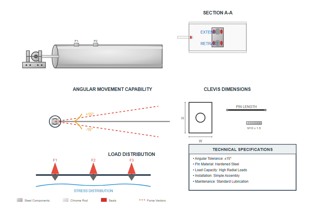
Simple pivoting mount using clevis and pin, allowing angular movement. Easy to install and adjust for misalignment.
Side loading, resulting from improper alignment or external forces, dramatically reduces cylinder life and should be minimized through careful mounting design and alignment procedures.
Even small amounts of misalignment can cause excessive wear on piston rods, seals, and bearings. Flexible mounting systems or alignment compensators should be considered in applications where perfect alignment cannot be guaranteed.
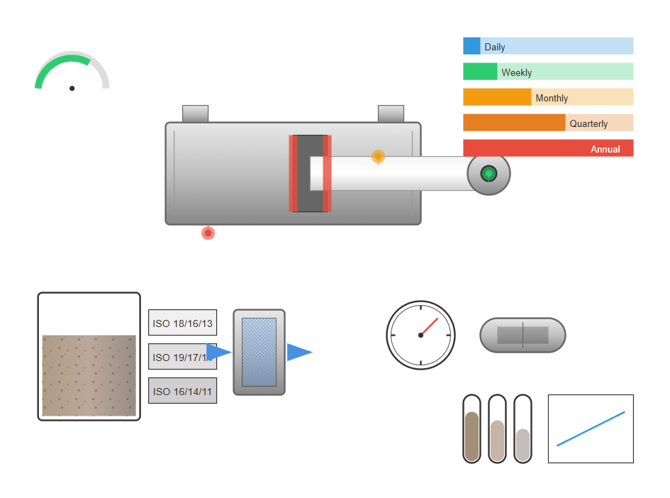
Proper maintenance practices and effective troubleshooting procedures maximize hydraulic cylinder performance and service life.
Effective maintenance maximizes cylinder hydraulic system reliability and lifespan. Regular inspection protocols should encompass visual examination for external leakage, rod surface condition assessment, and mounting hardware integrity verification.
Seal replacement intervals depend on operating conditions but typically range from 5,000 to 10,000 hours for continuously operating equipment. Fluid cleanliness proves critical, with contamination causing approximately 70% of hydraulic system failures.
Daily Inspections
Check for leaks, unusual noises, and proper operation
Weekly Inspections
Examine rod surface, check mounting hardware tightness
Monthly Inspections
Check fluid condition, test operation at all speeds
Quarterly Inspections
Measure cylinder drift, inspect cushioning performance
Annual Maintenance
Complete seal replacement, cylinder honing if needed
Understanding typical failure mechanisms enables proactive maintenance in cylinder hydraulic systems, allowing for early detection and prevention of catastrophic failures.
Results from chemical incompatibility, excessive temperatures, or contamination-induced wear, leading to leakage and reduced performance.
Caused by contamination or improper loading, compromises sealing effectiveness and accelerates wear of all components.
Occurs in high-cycle applications or when subjected to excessive side loading, creating internal leakage paths.
Manifest as end-of-stroke impacts, potentially damaging cylinders and connected equipment from excessive shock loading.
Modern diagnostic approaches for cylinder hydraulic systems combine traditional methods with advanced technologies, enabling accurate identification of potential issues before they result in system failure.
Measures system pressure during operation to identify internal leakage, valve issues, and seal effectiveness. Pressure decay tests help quantify leakage rates.
Detects high-frequency sounds generated by fluid turbulence, cavitation, or mechanical wear, identifying incipient failures before visible symptoms appear.
Identifies abnormal heat generation indicative of excessive friction, internal leakage, or bearing issues by visualizing temperature variations across components.
Proves particularly effective for detecting cushion problems, mounting issues, and rotating component imbalance by analyzing vibration frequency spectra.
1. Identify Symptom
Select the observed issue (leakage, slow operation, unusual noise, etc.)
2. Initial Inspection
- Check fluid level and condition
- Inspect for obvious leaks
- Verify electrical connections (if applicable)
- Check pressure gauge readings
3. Isolate Component
- Use process of elimination to identify affected component
- Check valve operation
- Test pump performance
- Inspect cylinder for external damage
4. Advanced Testing
- Perform pressure decay test
- Conduct ultrasonic leak detection
- Use thermal imaging to identify hot spots
- Analyze vibration patterns
5. Determine Root Cause
- Correlate test results with symptom
- Identify underlying cause (contamination, wear, misalignment, etc.)
- Document findings for future reference
6. Implement Solution
- Repair or replace damaged components
- Correct alignment or mounting issues
- Address contamination problems
- Perform system flushing if necessary
7. Verify Repair
- Test system operation
- Confirm symptom resolution
- Check for proper pressure and flow
- Document repair and test results