
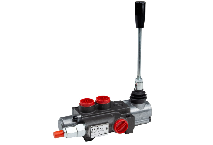
A direction control valve with manual handle operation for high pressure applications manages hydraulic fluid flow in systems operating at pressures up to 5000 psi. These valves combine mechanical actuation through a lever or handle with robust construction designed to withstand extreme pressure conditions. The handle provides direct manual control over spool positioning, allowing operators to redirect fluid flow between multiple ports while maintaining system integrity under demanding pressure loads. High-pressure rated valves typically feature reinforced cast iron or steel bodies, precision-machined internal passages, and specialized sealing systems to prevent leakage at elevated operating pressures.
Pressure ratings define the maximum continuous operating pressure a direction control valve can safely handle. Standard industrial valves operate between 3000 to 5000 psi, though some specialized units reach higher thresholds. The D03 mounting pattern supports pressures to 5000 psi on primary ports, while D05 patterns handle up to 4600 psi on main ports and 3000 psi on tank returns.
Pressure capacity depends on several construction factors. Body material selection plays a fundamental role—high-strength cast iron serves most applications, while carbon steel or stainless steel suits extreme conditions. Internal passage design minimizes pressure drop while maintaining structural strength. The valve must resist not just steady-state pressure but also transient spikes that occur during rapid directional changes or when stopping high-inertia loads.
Manufacturers specify pressure ratings for different port configurations. Pump and actuator ports typically carry full system pressure, while tank ports operate at lower ratings since they return fluid at near-atmospheric pressure. This differential allows engineers to optimize valve design for weight and cost while maintaining safety margins where needed.
Manual handles shift valve spools through direct mechanical linkage. When an operator moves the handle, physical force overcomes spring tension and any friction within the spool assembly. This mechanical advantage means a relatively small hand force can control high-pressure flows—typically 15 to 30 pounds of force operates valves managing thousands of psi.
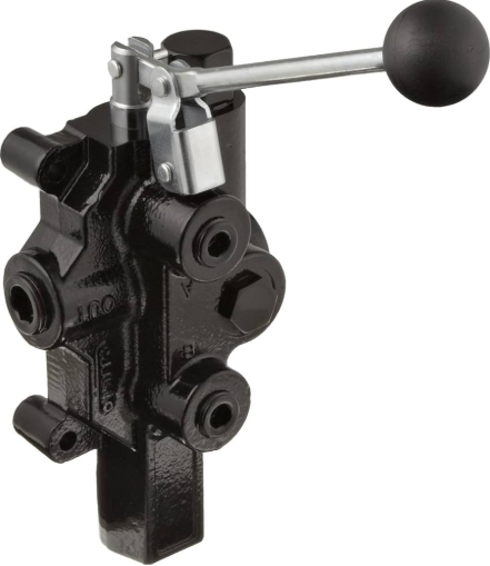
Handle designs vary by application requirements. Lever handles offer the quickest actuation and clearest position indication. The handle angle directly shows spool position—horizontal for neutral, forward for one flow path, backward for reverse. T-handles provide grip surface for applications requiring frequent cycling. Some high-pressure valves incorporate detent mechanisms that hold the spool in position without continuous operator force, useful for extended operations.
Handle extensions should never be used. Manufacturers design handle length to limit the force operators can apply to valve internals. Extending the handle increases leverage, potentially exceeding design limits and damaging the spool, body, or seating surfaces. Valve bodies can distort under excessive force, causing spool binding and eventual failure.
Most valves allow handle mounting in multiple orientations—typically four positions at 90-degree intervals. This flexibility helps equipment designers accommodate space constraints and operator ergonomics. However, position changes require proper reassembly with thread-locking compound to prevent loosening under vibration.
High-pressure manual valves come in several functional configurations based on port count and position options. The directional control valve selection depends on the actuator type and control requirements.
Two-position valves provide on-off control or simple directional switching. One handle position directs flow one way, the opposite position reverses flow direction. Spring-return designs automatically shift to a default position when released. Detent versions hold the selected position until manually changed, eliminating the need for continuous operator input.
Three-position valves add a neutral center condition between the two active positions. Center position behavior varies by spool design. Closed-center blocks all ports, stopping the actuator and directing pump flow to tank. Open-center connects all ports, allowing free actuator movement. Tandem-center provides load holding while unloading the pump. Each center condition serves specific application needs—closed for precise positioning, open for easy manual positioning, tandem for energy efficiency.
Four-way valves control double-acting cylinders or bidirectional motors. They provide the interconnection patterns needed to pressurize either side of an actuator while returning fluid from the opposite side. Three-way valves suit single-acting cylinders or other applications requiring only supply and exhaust functions.
Port configurations follow industry standards. NFPA D03 and D05 patterns ensure interchangeability across manufacturers. Subplate mounting simplifies installation and maintenance—valves bolt to a standardized manifold containing the plumbing connections. This approach concentrates fluid connections, reduces potential leak points, and allows valve replacement without breaking pipe fittings.
Choosing the correct valve requires matching multiple parameters to system requirements. Starting with pressure rating, the valve must exceed maximum system pressure with appropriate safety margin. Systems with shock loads or rapid cylinder deceleration generate pressure spikes substantially above steady operating levels. A system running at 3000 psi might see transients to 4500 psi, requiring a 5000 psi rated valve.
Flow capacity determines how quickly actuators move. Manufacturers specify rated flow at specific pressure drops, typically measured at 3000 psi differential. A valve rated for 20 GPM at 3000 psi exhibits predictable pressure loss at that flow rate. Undersized valves create excessive pressure drop, generating heat and wasting energy. Oversized valves cost more and may not control effectively at low flows.
Material compatibility matters in specialized environments. Standard mineral-based hydraulic oils work with conventional seal materials like Buna-N. Synthetic fluids, high temperatures, or corrosive additives require compatible elastomers—Viton for high heat, specialized compounds for water-glycol fluids. The valve body material must resist corrosion in marine or chemical environments.
Operating temperature affects both fluid viscosity and seal performance. Most industrial valves handle -20°F to 180°F, adequate for indoor equipment. Mobile equipment in extreme climates needs wider temperature ranges. Cold temperatures increase fluid viscosity, requiring more force to shift spools. High temperatures accelerate seal degradation.
Mounting space often constrains selection. Compact D03 valves fit tight spaces but limit flow capacity. Larger D05 and D08 sizes handle higher flows at lower pressure drops but need more installation room. Stack valve assemblies consolidate multiple control sections between common inlet and outlet manifolds, centralizing controls while reducing plumbing complexity.
High-pressure hydraulic systems demand strict safety protocols. Pressure releases enormous energy—a pinhole leak in a 5000 psi line can inject fluid through skin, causing severe tissue damage. Before any maintenance, the system must be depressurized and locked out.
Depressurization procedure: Stop the pump first, then close isolation valves. If the valve has manual override capability, cycle it in both directions to release trapped pressure between the valve and actuators. With cylinders, ensure loads are lowered or mechanically secured before releasing pressure. Accumulators store energy even after pump shutdown and require separate bleeding.
Handle forces provide operator feedback but can cause injury if not properly managed. Avoid standing in line with handle movement—if a detent releases suddenly or hydraulic pressure assists shifting, the handle can swing violently. Never place fingers in pinch points between the handle and adjacent structures.
Regular inspection catches problems before failure. Check for external leaks around handle brackets and body seals. Internal spool wear shows up as sluggish operation, excessive force requirements, or inability to hold position under load. Worn detents fail to hold position, allowing unintended movement. Contaminated fluid accelerates wear—maintain proper filtration and monitor fluid condition.
System pressure spikes during rapid direction changes or when decelerating heavy loads can exceed valve ratings momentarily. Relief valves protect against sustained overpressure but may not respond fast enough for transients. Proper circuit design using counterbalance valves or pressure-compensated flow controls prevents dangerous pressure peaks that could burst components.
Proper installation prevents many failures. Mounting surfaces must be flat within specified tolerances—warped mounting distorts the valve body, causing spool binding and potential cracking. Bolt torque specifications matter; overtightening on uneven surfaces creates stress concentrations. Use proper gaskets or sealant as specified, avoiding materials that degrade in hydraulic fluid.
Valve mounting affects both performance and maintenance accessibility. Most high-pressure directional valves use subplate mounting conforming to ISO 4401 standards. The subplate contains threaded or flanged ports connecting to system plumbing, while the valve bolts to the subplate’s machined surface.
Mounting orientation flexibility allows valves to install in any position—horizontal, vertical, or inverted—without affecting performance. This versatility helps designers optimize equipment layouts. However, consider handle accessibility for operation and maintenance. Operators need clear sight lines to handle position and adequate clearance for full handle travel. Maintenance technicians require access to remove the handle bracket and end cap for seal replacement.
Bolt torque follows manufacturer specifications, typically 19-20 ft-lbs for 3/8″ mounting bolts on mid-size valves, 11-12 ft-lbs for 5/16″ bolts on smaller units. Even torque distribution prevents body warping. The mounting surface must be flat and clean—any burrs or debris create uneven loading. Thread-locking compound prevents vibration loosening, especially important for mobile equipment.
Plumbing connections require careful attention to prevent contamination entry. Cap all ports until final connection. When breaking into the system for installation, minimize exposure time to airborne particles. Some installations benefit from in-line filters immediately upstream of sensitive proportional or servo valves, though manual directional valves tolerate contamination better than more precise components.
Port identification follows industry conventions: P for pump inlet, T for tank return, A and B for actuator work ports. Consistent port assignments simplify troubleshooting and reduce wiring errors in systems with solenoid pilot operation. Following the standard of connecting A to cylinder cap end and B to rod end means A-solenoid extends while B-solenoid retracts, intuitive for operators and electricians.
Spool-type directional valves exhibit three primary failure modes: external leakage, excessive internal leakage, or spool binding. Each presents distinct symptoms and requires specific remedies.
External leakage appears at seals—most commonly around the end cap where the handle bracket attaches. O-ring seals between the spool and body prevent high-pressure fluid from escaping. These seals wear from spool movement, contamination damage, or chemical incompatibility. Replacement requires removing the handle bracket and end cap, a straightforward procedure with proper seal kits. Clean all sealing surfaces thoroughly before installing new O-rings.
Internal leakage allows fluid to bypass the spool, passing from high to low pressure ports. All spool valves exhibit some internal leakage by design—the clearance between spool and bore must allow smooth shifting while minimizing bypass. Normal leakage ranges from 80 to 250 cm³/min depending on valve size and pressure. Excessive wear increases this clearance, reducing actuator speed and controllability. Valves showing significant performance degradation require replacement; internal components generally aren’t field-serviceable.
Spool binding prevents smooth operation or complete shifting. Causes include contamination particles scoring spool or bore surfaces, body distortion from improper mounting, or corrosion from incompatible fluids. Temporary relief sometimes comes from rotating the spool 180 degrees by removing the handle—this positions worn areas away from heavily loaded zones. However, binding usually indicates contamination problems requiring system flushing and component replacement.
Detent failures occur when the spring-loaded balls and notches that hold spool position wear excessively. The handle won’t stay in position or requires excessive force to engage. Replacement detent kits restore function, though recurring failures point to contamination or misalignment issues.
Heat generation indicates problems. Valves get warm during normal operation from internal friction and pressure drop, but excessive temperature suggests restriction. An undersized valve forces high velocity through limited passages, wasting energy as heat. Contamination partially blocking passages creates similar symptoms. Check for proper valve sizing and fluid cleanliness if temperatures exceed 150°F at the valve body.
Preventive maintenance extends valve life and prevents unexpected failures. Most manual directional valves require minimal routine service compared to electronically controlled units, but certain practices optimize reliability.
Fluid cleanliness ranks as the most critical maintenance factor. Hydraulic fluid lubricates, cools, and seals—contaminated fluid accelerates wear throughout the system. Maintain filtration according to system specifications, typically 10 to 25 micron absolute rating. Monitor fluid condition regularly, checking for water contamination (cloudy appearance), air entrainment (foaming), or oxidation (burnt smell, dark color). Replace fluid when condition indicators show degradation.
Seal replacement intervals depend on duty cycle and operating conditions. Manufacturers provide seal kits containing all necessary O-rings and gaskets for a particular valve model. Many industrial valves operate 5-10 years before requiring seal service. Mobile equipment in harsh environments needs more frequent attention—annually or every 2000 hours. Seal replacement requires only basic hand tools and takes 30-60 minutes per valve.
The process involves removing the handle bracket, then the end cap. Extract the spool carefully to avoid scratching internal surfaces. Replace all O-rings and backup rings from the kit, lubricating with clean hydraulic fluid before installation. Reassemble with proper bolt torque and thread locker. Testing under load verifies proper function.
Handle operation provides diagnostic information. Increased operating force indicates developing problems—wear, contamination, or seal swelling. Erratic operation or failure to return to neutral suggests spring issues or binding. Document baseline operating characteristics when valves are new; changes over time guide maintenance timing.
System flushing after major repairs removes contamination before it damages repaired or replacement components. Flush the entire circuit at high velocity but low pressure—typically 2 gpm per inch of line diameter at 200-300 psi. Continue until fluid samples show acceptable cleanliness. This prevents premature failure of freshly installed components.
Temperature monitoring during operation catches developing issues. Infrared thermometers provide non-contact measurement of valve body temperature. Sudden temperature increases indicate restriction, seal failure, or cavitation. Establishing baseline temperatures for normal operation helps identify abnormal conditions early.
Direction control valves function as part of larger hydraulic circuits, interacting with pumps, actuators, and other valves. Understanding these relationships optimizes system design and troubleshooting.
Pump compatibility affects valve selection. Fixed-displacement pumps require valves with appropriate center conditions to prevent pressure buildup when cylinders reach stroke ends. Open-center or tandem-center spools allow pump flow to return to tank at low pressure. Closed-center spools work with variable-displacement or pressure-compensated pumps that unload when flow isn’t needed.
Relief valves protect against overpressure but must coordinate with directional valve operation. Set relief pressure at least 10-20% above maximum working pressure but below component ratings. Position relief valves between pump and directional valve to protect the entire circuit. Additional relief valves or counterbalance valves may be needed for cylinders with negative loads (weight trying to run away).
Flow control valves regulate actuator speed by restricting flow. Meter-in control places the flow control between directional valve and actuator, providing precise speed control but potentially causing cavitation on the return side. Meter-out control restricts return flow, preventing load runaway and handling overrunning loads safely. The directional valve must accommodate the backpressure from flow controls without exceeding port ratings.
Check valves prevent reverse flow, useful for load holding or preventing actuator drift. Pilot-operated check valves allow flow in the restricted direction when hydraulic pilot pressure signals the valve to open. This prevents loads from falling when the directional valve shifts to neutral. External drain ports on pilot-operated checks prevent backpressure from holding them closed unintentionally.
Pressure gauges at strategic locations diagnose system problems. A gauge at the pump outlet shows system pressure. Gauges at cylinder ports show pressure differential, indicating load and potential binding. Watching pressures during directional valve shifting reveals issues—slow response suggests restriction, excessive pressure spikes indicate shock loading or inadequate flow control.
Operating pressure represents normal working pressure during typical use, while rated pressure indicates the maximum pressure the valve can safely handle continuously. Systems should operate 15-20% below rated pressure to provide safety margin for transient pressure spikes. For example, a valve rated at 5000 psi might operate in a 3500-4000 psi system, leaving headroom for momentary pressure peaks during load deceleration.
Yes, high-pressure valves function perfectly in lower-pressure systems. The tradeoff involves cost and size—valves rated for higher pressures use heavier construction and cost more than valves adequate for lower pressures. However, oversizing pressure rating causes no operational problems. The valve shifts normally and handles flows as specified regardless of actual operating pressure, as long as minimum pilot pressure requirements are met for pilot-operated models.
Service intervals depend on operating conditions rather than calendar time. Valves in clean industrial environments with quality fluid maintenance may run 10,000 hours before requiring seal replacement. Mobile equipment in contaminated environments needs inspection every 1,000-2,000 hours. Warning signs include external leaks, increased handle operating force, inability to hold position, or sluggish shifting. Preventive seal replacement before complete failure prevents damage to other components.
Increasing operating force indicates developing problems. Contamination particles score spool or bore surfaces, increasing friction. Seal swelling from incompatible fluids or high temperatures creates drag. Body distortion from improper mounting causes binding. Less commonly, internal corrosion or material buildup restricts spool movement. Address the root cause rather than just accepting higher operating forces—if left unattended, the valve will eventually fail to shift completely.
Understanding how manual handles control high-pressure hydraulic systems helps operators and maintenance personnel keep equipment running reliably. These valves represent mature technology proven across decades of industrial service. Their mechanical simplicity and robust construction suit applications where direct operator control makes sense—setup operations, maintenance procedures, or situations where electronic control adds unnecessary complexity. Proper selection based on pressure, flow, and environmental requirements, combined with basic maintenance practices, ensures these valves deliver years of trouble-free operation.