
Updated March 2026 | Hydraulic Valve Technical Guide | 8 min read
If you own a Speeco, Huskee, County Line, Brave, Dirty Hand Tools, or Yardmax log splitter, there's a very good chance your machine runs an Energy Manufacturing 0C000908 valve — even if you've never heard that part number before. Energy Manufacturing, based in Monticello, Iowa, has been building this particular directional control valve for decades, and it shows up as the OEM component on more residential and light-commercial log splitters than any other single valve on the market.
I've pulled dozens of these valves off splitters that came in for service. Some had 15 years of use on them. Others barely survived two seasons. The difference almost always comes down to how well the owner understood what this valve actually does — and how to keep it working. This guide covers everything you need to know about the 0C000908, from how it operates to why it fails, based on real-world shop experience rather than catalog copy.
Energy 0C000908 — Key Specifications at a Glance
| Valve Type | 3-position, 4-way, single-spool monoblock |
| Max Flow Rate | 20 GPM (76 LPM) |
| Working Pressure | 2,500 PSI (172 bar) |
| Relief Valve Preset | 2,000 PSI ± 200 PSI (adjustable 400–2,500 PSI) |
| Detent Kickout Pressure | 750 PSI (adjustable up to 2,000 PSI) |
| Work Ports | 1/2" NPT (F) |
| Inlet / Outlet Ports | 3/4" NPT (F) |
| Max Relief Flow | 10 GPM (38 LPM) |
At its core, the 0C000908 is a three-position, four-way, single-spool monoblock directional control valve rated for up to 20 GPM and 2,500 PSI working pressure. Those specs alone don't tell you much — plenty of valves hit those numbers. What sets this valve apart is the detent mechanism on the retract stroke.
When you push the handle forward to extend the ram and split a log, the valve is spring-centered. Release the handle, and it snaps back to neutral on its own. That's the safety side of the design — you maintain active control throughout the splitting stroke. But on the retract side, a pressure-released detent holds the spool in position so the ram travels all the way back without you holding the lever. Once the cylinder bottoms out and pressure spikes past the detent threshold (factory-set around 750 PSI), the spool kicks back to neutral automatically.
This auto-return detent is the reason Energy dominates the residential log splitter market. It turns a two-handed operation into a one-handed one, which means faster splitting cycles and less operator fatigue during a long day of processing firewood. The tandem center spool configuration routes oil back to tank in neutral, keeping heat buildup low during idle periods — a real advantage for air-cooled systems that run for hours at a stretch.
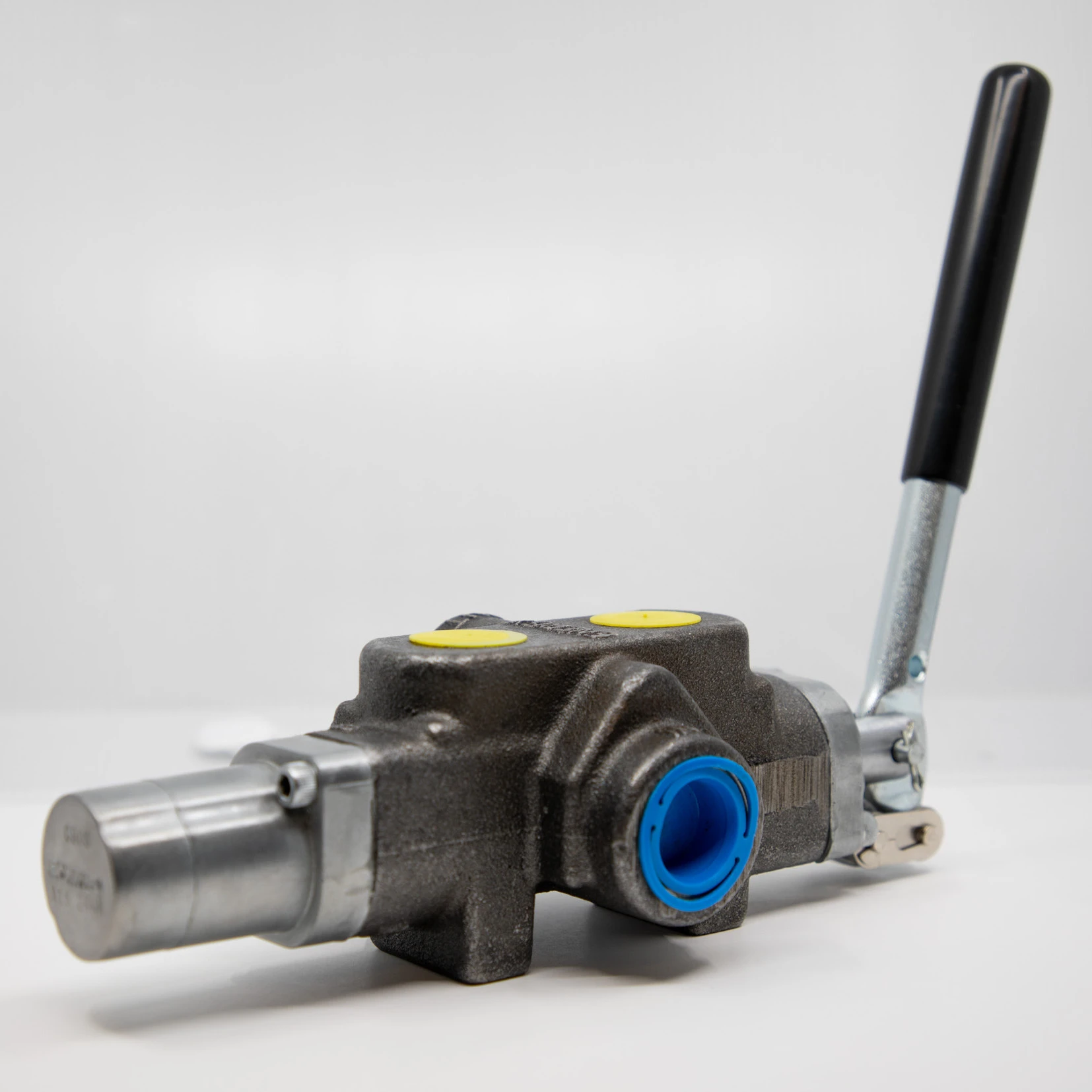
The Energy 0C000908 — handle bracket on left, detent cover assembly on right. Note the four NPT ports along the valve body.
The 0C000908 uses 1/2-inch NPT female work ports (A and B) and 3/4-inch NPT female inlet and outlet ports. The work port nearest the handle bracket controls the retract function — this is the opposite of what you'll find on Prince LS3000 series valves, and it's the single most common source of confusion when people swap one for the other. Install it backward and your ram extends when it should retract. I've seen this mistake more times than I can count, and it's worth double-checking before you tighten anything down.
⚠ Installation Note: The Energy 0C000908 and Prince LS3000 have reversed work port orientations. On the Energy valve, the work port closest to the handle controls retract. On the Prince, it controls extend. Connecting lines without verifying port function first will cause the ram to operate in reverse.
The built-in relief valve comes preset to approximately 2,000 PSI (plus or minus 200 PSI) and is adjustable from 400 PSI all the way up to 2,500 PSI using a slotted screw beneath the hex cap. Maximum flow through the relief circuit is limited to 10 GPM — an important detail if your pump pushes more than that. Running excess flow through a relief valve that can't handle it generates dangerous heat and will cook your hydraulic fluid in short order. Back pressure at the tank port should stay under 200 PSI, or the detent behavior gets unpredictable. Energy Manufacturing's own documentation (Form 17498X) flags this as a critical installation parameter.
The detent mechanism lives under a small cover on the end of the valve opposite the handle. Inside, you'll find a stack of components: a spring, detent balls, a sleeve, and a spool stop. When the operator pulls the lever into the retract position, these balls lock into a groove on the spool and hold it in place. Hydraulic pressure from the cylinder's end-of-stroke builds against the spool until it overcomes the detent spring force, pushing the balls out of their groove and releasing the spool back to center.
After a few seasons of heavy use, the detent can start acting up. The most common symptom is intermittent holding — the handle stays engaged three out of four times, then randomly pops back to neutral mid-stroke. Usually, this is a wear issue with the detent balls or the groove they seat into. Tightening the adjustment sleeve inside the detent cover often buys you another season. If that doesn't fix it, Energy sells a complete detent cover rebuild kit (part number 36561B) that includes all the internals.
One thing worth mentioning: vibration from the gas engine can affect detent engagement. Several splitter owners have reported premature kickout on machines without proper rubber isolation mounts between the engine and the frame. If your detent problems seem random and inconsistent, check your engine mounting before tearing into the valve.
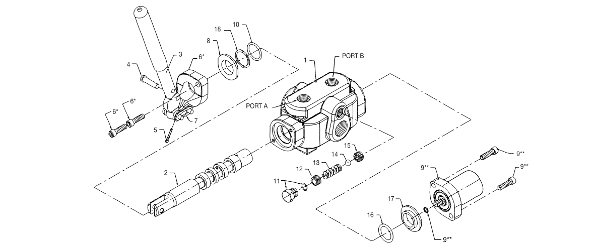
Detent cover exploded view — replace all internal components as a set when rebuilding.
Getting the relief setting right on an 0C000908 requires a pressure gauge — don't try to do this by feel. Mount a glycerin-filled gauge rated for at least 4,000 PSI at a test point between the pump outlet and the valve inlet. Run the engine and bring the hydraulic oil up to normal operating temperature first, because cold oil behaves differently under pressure and any adjustments you make won't reflect real-world conditions.
Remove the hex cap to expose the slotted adjustment screw. Clockwise increases pressure; counterclockwise decreases it. The procedure is straightforward: fully extend the cylinder ram against a stop, read the gauge, and adjust until you hit your target. Most residential splitters perform well at 2,000 to 2,500 PSI depending on cylinder bore size and the hardness of wood you're splitting.
Splitting Force by Cylinder Bore Size and Pressure
| Cylinder Bore | @ 2,000 PSI | @ 2,500 PSI | @ 3,000 PSI |
|---|---|---|---|
| 3.5" bore | 19,200 lbs | 24,050 lbs | 28,860 lbs |
| 4" bore | 25,130 lbs | 31,420 lbs | 37,700 lbs |
| 4.5" bore | 31,810 lbs | 39,760 lbs | 47,710 lbs |
| 5" bore | 39,270 lbs | 49,090 lbs | 58,900 lbs |
Force = Pressure × Piston Area (π/4 × bore²). Values rounded to nearest 10 lbs.
If your gauge reads well below where you set the relief and the machine can't split wood it used to handle easily, don't automatically blame the valve. Pressure relief valve issues account for a surprisingly small percentage of low-pressure complaints. In many cases, a worn hydraulic pump is the actual culprit — the valve is just taking the blame because it's easier to access.
Energy designed the 0C000908 so you can replace the spool seals without disconnecting the valve from the hydraulic system. That's a genuine time-saver for field repairs. Start by making absolutely sure the engine is off, the spark plug wire is disconnected, and all pressure has bled from the system. Then remove the detent cover, pull the handle bracket, and slide the seal retainers out from both ends of the bore.
The spool uses two different O-ring sizes: a 7/8 x 1-1/16 inch O-ring on the handle side and a 13/16 x 1-1/16 inch O-ring on the detent side. Each one sits behind a backup ring — pay attention to the orientation of the backup ring during reassembly. One side is slightly concave and the other is flat. The concave side faces the O-ring. Get this wrong and you'll be chasing a leak that shouldn't exist.
Pro Tip: Apply thread sealer (Loctite or equivalent) to the detent assembly stud threads before reinstalling. Energy specifies this because vibration can loosen the stud over time. Torque mounting screws to 70–90 in-lbs.
When the original Energy valve is beyond repair — or you're building a custom splitter and want to evaluate your options — several compatible valves are worth considering. Each has trade-offs in port layout, flow capacity, and price point.
| Valve | Max Flow | Work Ports | Notes |
|---|---|---|---|
| Energy 0C000908 | 20 GPM | 1/2" NPT | OEM valve. Handle-side port = retract. Made in USA. |
| Prince LS3000-1 | 25 GPM | 1/2" NPT | Reversed work port orientation. Handle-side port = extend. Heavier construction. |
| Prince LS3000-2 | 25 GPM | 3/4" NPT | Larger work ports for higher-flow systems. Same reversed port layout. |
| Cross BA Series | 20 GPM | 1/2" NPT | Budget alternative. Detent quality varies by production batch. Verify mounting bolt pattern. |
Always verify port orientation and mounting dimensions before ordering a replacement. A valve that bolts up doesn't necessarily plumb up.
For splitters that handle higher flow rates or need auxiliary hydraulic functions — like operating a log lift alongside the splitting cylinder — stepping up to a two-spool monoblock valve opens up significant capability. Just remember that the 0C000908's internal relief is only rated for 10 GPM. If your pump exceeds that and you're relying on the built-in relief as your system safety, you need an external inline relief valve sized for full pump flow.
If your application is a new build rather than a direct replacement, single-spool monoblock valves from established hydraulic suppliers generally offer tighter spool tolerances and better chrome plating than generic units. Poor spool finish leads to internal leakage, which means lost force at the wedge and excessive heat generation in the circuit.
The number one killer of log splitter valves isn't pressure or cycles — it's contamination. Dirt, wood chips, and moisture find their way into hydraulic reservoirs on outdoor equipment faster than most people realize. A particle smaller than what you can see with the naked eye is enough to score the spool lands and create an internal leak path. Once that starts, it only accelerates.
Seasonal Maintenance Checklist
✅ Replace hydraulic filter at the start of every splitting season — not when it looks dirty
✅ Use AW46 hydraulic oil (or manufacturer-specified grade) and keep the reservoir topped off
✅ Inspect all fittings and hose connections for seepage before first use
✅ Store splitter with cylinder fully retracted to protect the rod from moisture and debris
✅ Run the machine for 10 minutes at idle before putting it under load — cold oil stresses seals
✅ Check the detent cover screws for tightness — vibration loosens them over time
Low fluid levels cause the pump to cavitate, which introduces air bubbles and accelerates wear on every component downstream — including the valve. Proper warmup and pressure-testing procedures are one of those simple habits that add years to your equipment, and most owners skip it entirely.
Before you order a new 0C000908, rule out the cheap stuff first. A clogged suction strainer can mimic valve failure almost perfectly — the splitter loses power, cycle times get longer, and nothing seems to respond correctly. Same goes for a worn hydraulic pump that's lost its high-pressure section. The valve might be doing exactly what it's supposed to, but the flow and pressure feeding it aren't up to spec.
Check your hydraulic lines for kinks, loose fittings, and collapsed hoses — especially the suction line between the reservoir and pump. A partially collapsed suction hose starves the pump without leaving any visible external leak. Tighten every fitting, inspect every hose, and verify pump output with a flow meter before condemning the valve. For a full diagnostic walkthrough, our hydraulic system low-pressure troubleshooting guide covers the complete step-by-step process.
Need a Replacement Directional Control Valve?
Browse our full range of monoblock hydraulic directional control valves — available in 1 to 7 spool configurations with manual, solenoid, and pneumatic actuation options.