The field of fluid and hydraulics represents one of the most fundamental branches of engineering science, playing a crucial role in countless industrial applications and everyday machinery. From the massive excavators that shape our landscapes to the precise control systems in aerospace engineering, hydraulic technology has revolutionized how we harness and control power. Understanding the principles of fluid and hydraulics is essential for engineers, technicians, and anyone interested in modern mechanical systems.
Section 1: Physical Properties of Fluids
The foundation of fluid and hydraulics begins with understanding the physical properties of liquids. Liquids, unlike gases, are considered incompressible fluids under normal operating conditions, making them ideal for transmitting force and motion in hydraulic systems.
The key physical properties that define how fluids behave in hydraulic applications include density, viscosity, compressibility, and surface tension.
Density, expressed as mass per unit volume, determines the weight of the hydraulic fluid and affects the overall system design. In fluid and hydraulics applications, typical hydraulic oils have densities ranging from 850 to 900 kg/m³.
Viscosity, perhaps the most critical property, measures a fluid's resistance to flow. The viscosity of hydraulic fluids must be carefully selected to ensure proper lubrication while minimizing energy losses. Temperature significantly affects viscosity, with fluids becoming less viscous as temperature increases, which is why thermal management is crucial in fluid and hydraulics systems.
The definition for hydraulic systems fundamentally relies on these fluid properties. A hydraulic system uses incompressible fluid to transmit power from one location to another, multiplying force through the application of Pascal's law.
Surface tension and capillarity also play roles in fluid and hydraulics, particularly in small passages and clearances. These properties affect fluid behavior in narrow gaps, influencing leakage rates and the effectiveness of seals.
Viscosity vs Temperature Relationship
Typical viscosity behavior of hydraulic fluids under varying temperatures
Key Fluid Properties
- Density: 850-900 kg/m³ for hydraulic oils
- Bulk Modulus: 1.5-2.0 GPa for mineral oils
- Viscosity Index: Measures temperature resistance
- Pour Point: Indicates low-temperature performance
Section 2: Fundamentals of Hydrostatics
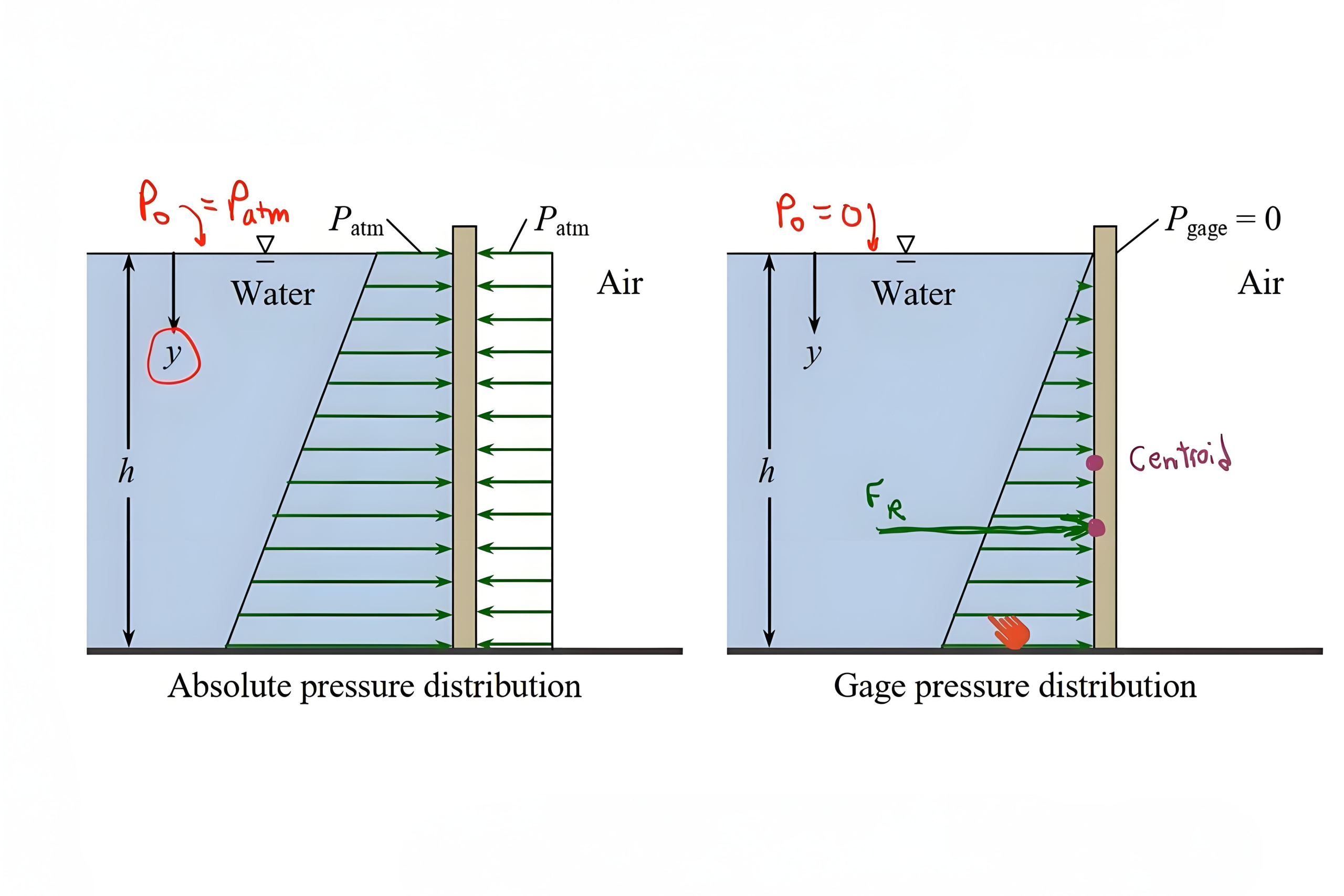
Hydrostatics, the study of fluids at rest, provides the theoretical foundation for understanding fluid and hydraulics. The principle of hydrostatic pressure states that pressure in a static fluid increases linearly with depth, following the equation P = ρgh + P₀, where ρ is fluid density, g is gravitational acceleration, h is depth, and P₀ is surface pressure.
Pascal's law, the cornerstone of fluid and hydraulics, states that pressure applied to a confined fluid is transmitted equally in all directions throughout the fluid. This principle enables hydraulic systems to multiply force, as demonstrated in hydraulic presses, lifts, and brakes.
When a small force is applied to a small piston, it creates pressure that, when transmitted to a larger piston, generates a proportionally larger force. The mechanical advantage equals the ratio of the piston areas, making fluid and hydraulics an efficient means of force multiplication.
In industrial hydraulic systems, operating pressures typically range from 1,000 to 5,000 psi, though specialized applications may use pressures exceeding 10,000 psi.
Buoyancy, another hydrostatic principle, affects fluid and hydraulics systems, particularly in reservoir design and component mounting. The buoyant force equals the weight of displaced fluid, influencing the behavior of floating components and air bubbles in hydraulic fluids.
Hydrostatic Pressure Equation
P = ρgh + P₀
Pressure
P
Fluid Density
ρ
Gravitational Acceleration
g
Depth/Surface Pressure
h / P₀
Typical Operating Pressures
Industrial Systems
1,000 - 5,000 psi
High-Pressure Applications
10,000+ psi
Section 3: Fundamentals of Hydrodynamics
Hydrodynamics examines fluids in motion, providing essential insights for fluid and hydraulics system design. The continuity equation, expressing conservation of mass, states that the product of cross-sectional area and velocity remains constant along a streamline in steady flow. In practical applications, engineers use a hydraulic pressure gauge to monitor these dynamic conditions and verify that system parameters align with theoretical predictions.
Continuity Equation
A₁v₁ = A₂v₂ = Q
The product of cross-sectional area and velocity remains constant along a streamline, ensuring conservation of mass in fluid flow.
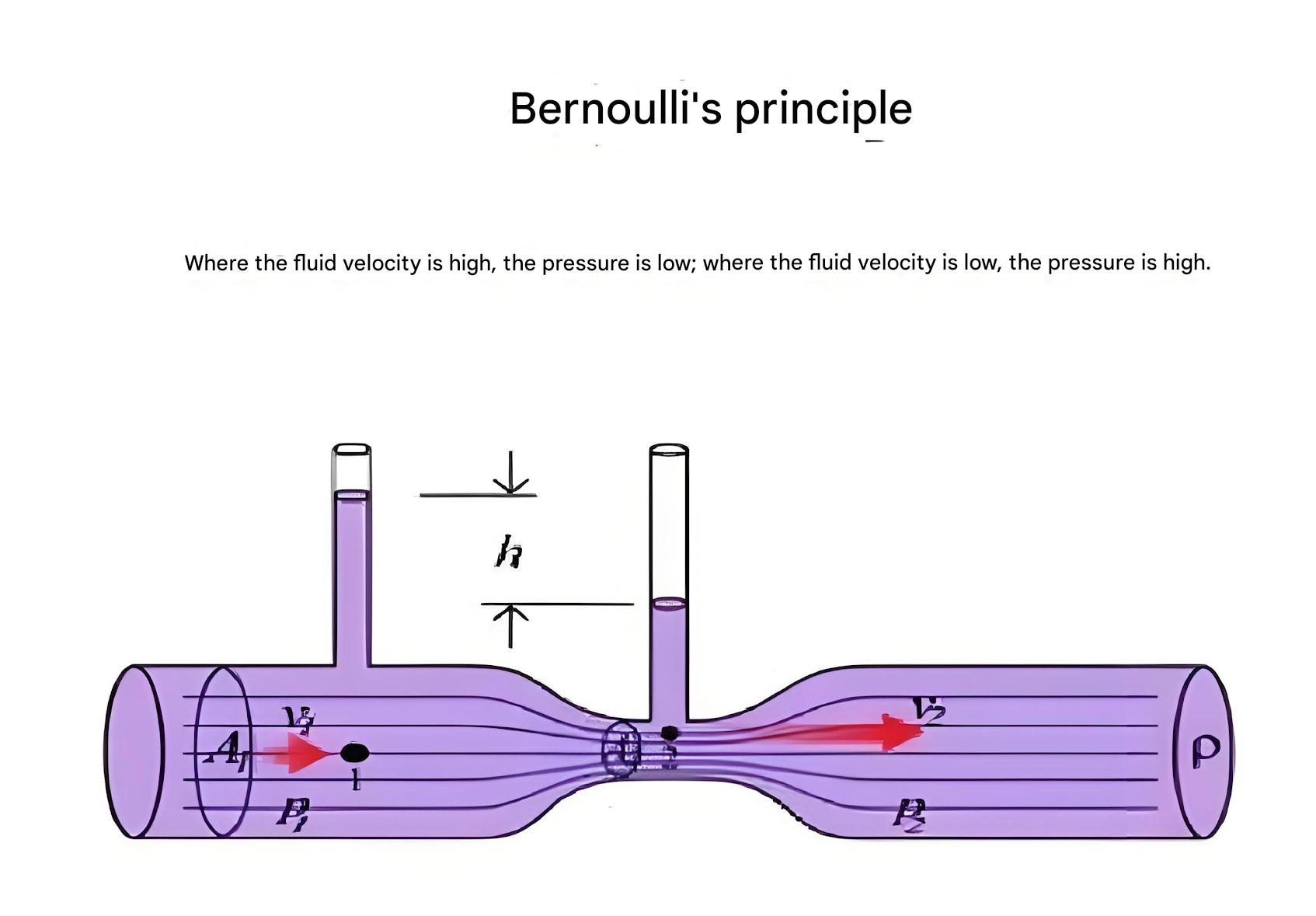
Bernoulli's Equation
P + ½ρv² + ρgh = constant
Relates pressure, velocity, and elevation in flowing fluids, showing the conservation of energy in fluid flow.
Reynolds Number
Re = (ρvD)/μ
Predicts flow regime: laminar (Re < 2300), transitional, or turbulent (Re > 4000) in fluid systems.
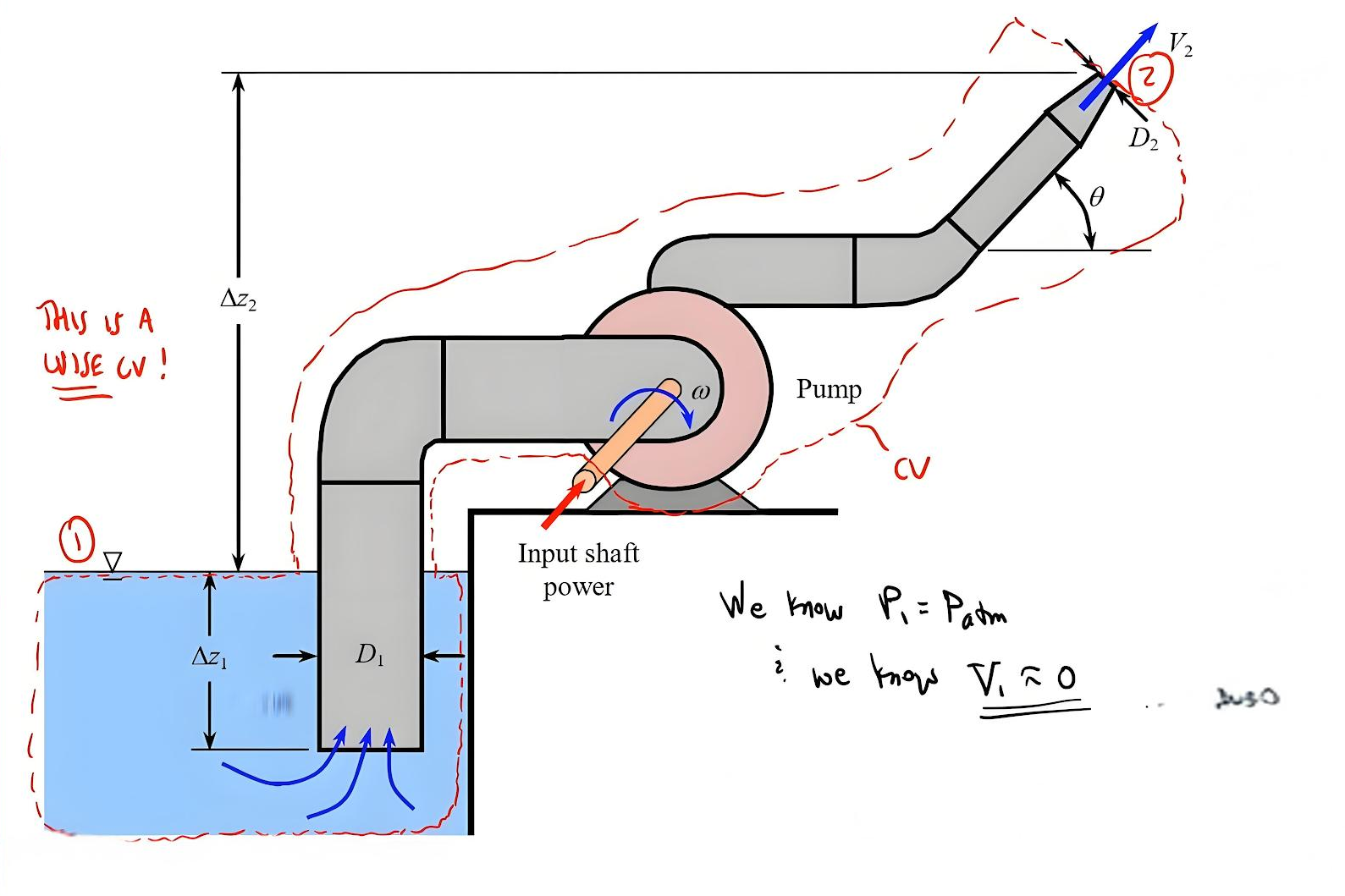
Bernoulli's equation, fundamental to fluid and hydraulics, relates pressure, velocity, and elevation in flowing fluids. The equation demonstrates that total energy remains constant along a streamline, with trade-offs between pressure energy, kinetic energy, and potential energy.
Understanding what are the principles of hydraulics requires examining both laminar and turbulent flow regimes. Laminar flow, characterized by smooth, parallel fluid layers, occurs at low velocities and is described by the Reynolds number (Re < 2300 for pipe flow). Turbulent flow, with chaotic fluid motion and mixing, dominates at higher velocities (Re > 4000).
The momentum equation in fluid and hydraulics describes forces acting on flowing fluids, essential for calculating forces on pipe bends, valves, and actuators. These forces can be substantial in high-flow systems, requiring proper support and anchoring of components.
Section 4: Pressure Losses in Fluid Flow
Pressure losses in fluid and hydraulics systems directly impact efficiency and performance. These losses, categorized as major losses (friction in straight pipes) and minor losses (fittings, valves, and direction changes), must be minimized through careful system design.
The Darcy-Weisbach equation quantifies friction losses in pipes, with the friction factor depending on Reynolds number and pipe roughness.
In laminar flow conditions, common in fluid and hydraulics systems with high-viscosity oils, the friction factor equals 64/Re, making pressure drop calculations straightforward. The Hagen-Poiseuille equation describes laminar flow pressure drop as proportional to flow rate, viscosity, and pipe length, and inversely proportional to the fourth power of pipe diameter. Understanding these pressure drop characteristics is essential for properly sizing components like hydraulic pressure relief valve, which must respond accurately to system pressure changes to maintain safe operating conditions.
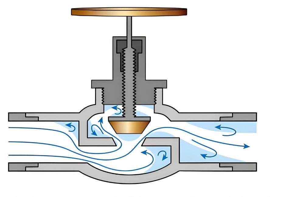
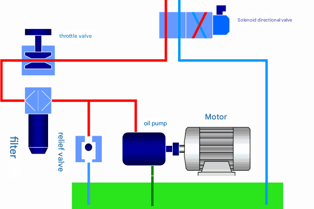
Minor losses at valves, fittings, and flow restrictions often exceed friction losses in compact hydraulic systems. The hydraulic flow control valve, essential for regulating flow rates in hydraulic circuits, introduces controlled pressure drops to achieve desired flow characteristics.
Pressure Loss vs Flow Rate
Darcy-Weisbach Equation
hf = f × (L/D) × (v²/(2g))
- hf: Head loss due to friction
- f: Friction factor
- L: Pipe length
- D: Pipe diameter
- v: Flow velocity
- g: Gravitational acceleration
Factors Contributing to Pressure Loss
Pipe Friction (Major Losses)
Caused by fluid viscosity and pipe wall roughness, increases with pipe length and flow velocity.
Fittings and Valves (Minor Losses)
Elbows, tees, valves, and other components create turbulence and flow restrictions.
Pipe Diameter Changes
Sudden expansions or contractions disrupt flow patterns and create pressure drops.
Fluid Viscosity
Higher viscosity fluids create greater resistance to flow, increasing pressure losses.
Section 5: Flow Through Orifices and Clearances
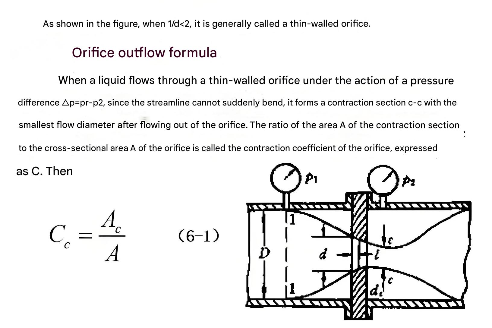
Flow through small openings is fundamental to fluid and hydraulics control and presents unique challenges. Orifice flow, governed by the orifice equation Q = Cd × A × √(2ΔP/ρ), depends on the discharge coefficient, orifice area, and pressure differential.
Clearance flow between moving parts represents both a necessity for lubrication and a source of internal leakage in fluid and hydraulics components. The flow through annular clearances, such as between pistons and cylinders, follows specialized equations considering both pressure-driven and motion-induced (Couette) flow.
The hydraulic pressure relief valve exemplifies precision orifice application in fluid and hydraulics safety systems. These valves protect circuits from overpressure by opening a calibrated orifice when pressure exceeds a preset limit.
Orifice Flow Equation
Q = Cd × A × √(2ΔP/ρ)
Where Q is flow rate, Cd is discharge coefficient (0.6-0.8), A is orifice area, ΔP is pressure differential, and ρ is fluid density.
Section 6: Hydraulic Shock and Cavitation Phenomena
Hydraulic shock, or water hammer, represents one of the most destructive phenomena in fluid and hydraulics systems. When flow velocity changes rapidly, such as during sudden valve closure, pressure waves propagate through the fluid at sonic velocity.
The Joukowsky equation estimates pressure rise as ΔP = ρ × c × Δv, where c is the wave speed and Δv is the velocity change. In rigid pipes with typical hydraulic oils, wave speeds approach 1,400 m/s, generating pressure spikes potentially exceeding system design limits.
Cavitation in fluid and hydraulics occurs through two mechanisms: vaporous cavitation from pressure reduction below vapor pressure, and gaseous cavitation from dissolved air release. Both forms damage components through erosion, noise, and performance degradation.
Cavitation Warning Signs
- Increased noise and vibration
- Reduced flow rate and system performance
- Component erosion and pitting
- Overheating and fluid degradation
Advanced Considerations in Fluid and Hydraulics
Modern fluid and hydraulics systems incorporate sophisticated control strategies and components. Proportional and servo valves provide precise flow and pressure control through electronic feedback systems. These advanced valves enable complex motion profiles and force control in industrial automation, aerospace, and mobile equipment applications.
Advanced Control Systems
Proportional and servo valves with electronic feedback enable precise flow control and complex motion profiles, essential for high-performance applications in automation and aerospace.
Contamination Control
Advanced filtration systems (3-10 micron ratings) and fluid analysis prevent premature component failure by removing contaminants and monitoring fluid condition.
Energy Efficiency
Variable displacement pumps, load-sensing systems, and hybrid hydraulic-electric drives reduce power consumption and heat generation in modern systems.
The science of fluid and hydraulics encompasses fundamental physical principles and practical engineering applications. From the basic properties of hydraulic fluids to complex system dynamics, each aspect contributes to effective hydraulic system design and operation.
As technology advances, fluid and hydraulics continues to evolve, incorporating digital control, condition monitoring, and energy optimization. Engineers and technicians who master these principles can harness the remarkable power density and controllability that make fluid and hydraulics indispensable in modern industry.
Whether designing new systems or maintaining existing equipment, a thorough understanding of hydraulic fundamentals ensures safe, efficient, and reliable operation across diverse applications.