
Gear pumps are among the most commonly utilized hydraulic pumps in modern hydraulic systems, offering reliable performance across various industrial applications. These positive displacement pumps operate through the meshing action of gears to transfer fluid from inlet to outlet.
The fundamental design of gear pumps can be categorized into two primary structural types: external gear pumps and internal gear pumps, each offering distinct advantages for specific applications.
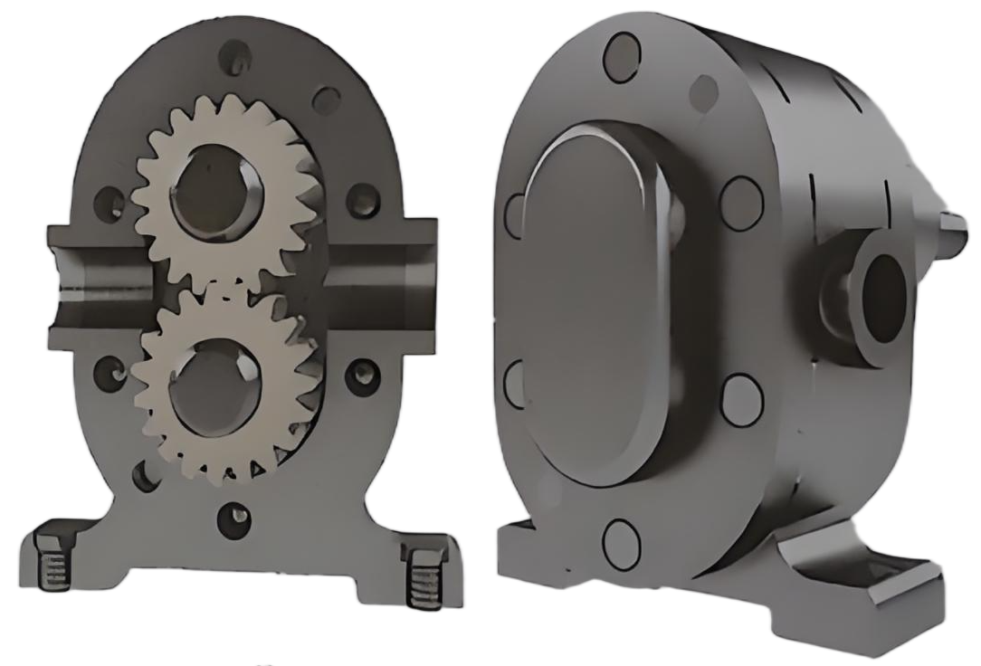
The operational mechanism of external gear pumps represents a fundamental concept in hydraulic engineering. As illustrated in typical hydraulic system configurations, an external gear pump consists of a pair of externally meshing gears housed within a pump casing. The gears are enclosed by end covers on both sides, creating a sealed environment.
When the gears rotate in their designated direction, the suction chamber on the right side experiences a gradual disengagement of the meshing teeth. This action causes the sealed working chamber volume to progressively increase, creating a partial vacuum condition. The resulting pressure differential draws hydraulic fluid from the reservoir into the pump, filling the tooth spaces completely.
In the pressure zone, the gear teeth progressively enter into mesh, causing the sealed working chamber volume to continuously decrease. This reduction in volume forces the hydraulic fluid out of the pump under pressure. The suction and pressure zones are effectively separated by the meshing gear teeth and the pump body structure.
The separation between suction and pressure zones is crucial for maintaining the pressure differential that enables gear pumps to function effectively.
External gear pump operation showing fluid flow path through meshing gears
The accurate calculation of displacement in external gear pumps requires careful consideration of meshing principles. For approximate calculations, the displacement can be considered equal to the sum of the tooth space volumes of both gears. When assuming that the tooth space volume equals the tooth volume, and given specific parameters, the pump displacement can be expressed mathematically.
Theoretical displacement formula for gear pumps:
Practical displacement formula:
(Accounts for tooth space volume slightly exceeding tooth volume)
Actual output flow rate:
V
Displacement
z
Number of teeth
m
Module
b
Tooth width
n
Rotational speed
ηv
Volumetric efficiency
D
Pitch diameter
h
Tooth height
The flow rate represented in these equations indicates the average flow of gear pumps. In reality, due to the non-uniform rate of volume change in the pressure chamber during the gear meshing process, the instantaneous flow rate exhibits pulsation characteristics. The flow pulsation rate (σ) can be calculated using the maximum and minimum instantaneous flow rates (qmax and qmin):
Flow pulsation comparison between external and internal gear pumps
Analysis of flow pulsation in gear pumps reveals that external gear pumps with fewer teeth exhibit higher flow pulsation rates, potentially exceeding 0.2. In contrast, internal gear pumps demonstrate significantly lower flow pulsation rates, contributing to smoother operation.
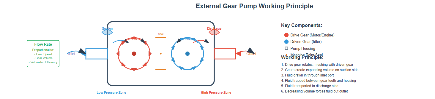
For gear pumps to operate smoothly, the gear meshing overlap ratio must exceed 1. This requirement inevitably results in two pairs of teeth meshing simultaneously, trapping a portion of hydraulic fluid between the closed cavity formed by these tooth pairs.
The reduction in enclosed cavity volume causes the trapped fluid to experience extreme pressure, forcing it through available clearances. This generates heat and subjects mechanical components, particularly bearings, to additional loads. Conversely, the expansion of the enclosed cavity volume creates localized vacuum conditions.
The conventional solution for eliminating oil trapping involves machining relief grooves in the side cover plates. These grooves allow the enclosed cavity to communicate with the pressure chamber when its volume decreases and with the suction chamber when its volume increases.
Oil trapping phenomenon in gear pumps and relief groove solution
In external gear pumps, pressurized fluid from the high-pressure chamber can leak to the low-pressure chamber through three primary pathways. Understanding these leakage paths is crucial for optimizing pump efficiency.
Leakage through the clearance at the gear meshing line, accounting for approximately 10-15% of total leakage.
Leakage through the tip clearance between the pump body bore and the gear tip circle, accounting for about 10-20% of total leakage.
Leakage through the end face clearance between the gear side faces and the side cover plates, representing 70-80% of total leakage.
This substantial leakage contribution explains why conventional gear pumps exhibit relatively low volumetric efficiency and face limitations in achieving high output pressures. To enhance the pressure capabilities of gear pumps, addressing end face leakage becomes the primary engineering challenge.
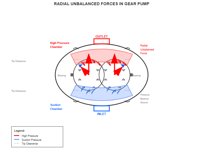
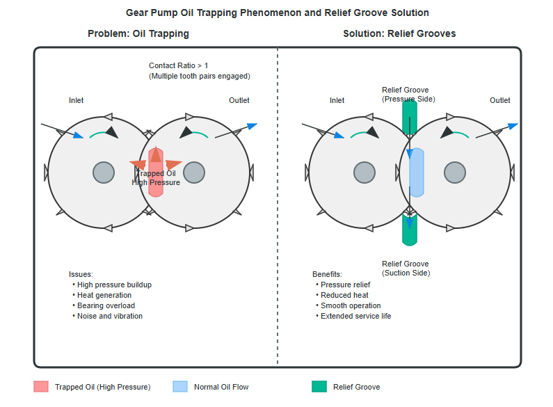
Radial force distribution on gear teeth in operating pump
Within gear pumps, the pressure distribution on the gear tip circle is inherently unequal. The gear tip circle and tooth profile surfaces in the high-pressure and suction chambers experience working pressure and suction pressure respectively.
The combined effect of these hydraulic pressures generates a radial force (unbalanced force) acting on the gear and bearings. Higher working pressures result in proportionally greater radial unbalanced forces.
To mitigate the effects of radial unbalanced forces, some pump designs incorporate reduced pressure port dimensions, limiting pressure oil action to one or two teeth. Additionally, appropriate tip clearance increases prevent gear-to-casing contact under pressure loads.
High-pressure gear pumps often feature pressure balancing grooves to reduce radial imbalance effects, extending bearing life and improving overall reliability.
Enhancing the pressure capabilities of gear pumps necessitates minimizing end face leakage, typically accomplished through automatic end face clearance compensation methods. The compensation principle involves utilizing specialized channels to direct pressurized fluid from the pump's pressure chamber to the outer side of bushings, generating hydraulic forces that press the bushings against the gear end faces.
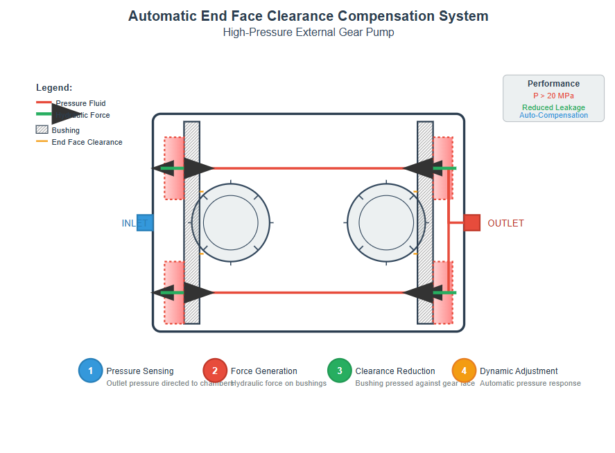
Automatic end face clearance compensation system in high-pressure gear pumps
These forces must exceed the forces acting on the inner side of the bushings from the gear end faces to ensure that bushings automatically maintain tight contact with gear end faces under all pressure conditions.
Pressurized fluid from outlet is directed to compensation chamber
Hydraulic pressure creates force on compensation plate or bushing
Bushing is pressed against gear face, minimizing leakage path
System automatically adjusts with pressure changes for optimal clearance
This automatic adjustment mechanism reduces internal leakage through end faces, enabling higher pressure operation. Modern high-pressure gear pumps utilizing these compensation techniques can achieve operating pressures exceeding 20 MPa, significantly expanding their application range in industrial hydraulic systems.
Internal gear pumps are available in two primary tooth profile configurations: involute tooth profile and cycloidal tooth profile (also known as rotor pumps). Their operating principles and main characteristics closely parallel those of external gear pumps, though with distinct advantages in certain applications.
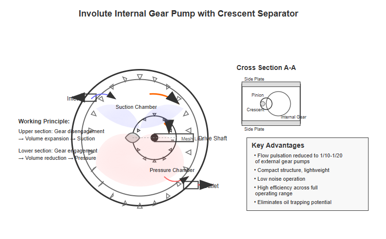
Involute internal gear pump with crescent-shaped separator
In involute internal gear pumps, the meshing small gear and internal gear, together with side plates, form sealed volumes. A crescent-shaped separator and the gear meshing line divide these volumes into suction and pressure chambers.
When the drive shaft rotates the small gear, the internal gear rotates in the same direction. The upper section experiences tooth disengagement with increasing sealed volume (suction chamber), while the lower section experiences tooth engagement with decreasing sealed volume (pressure chamber).
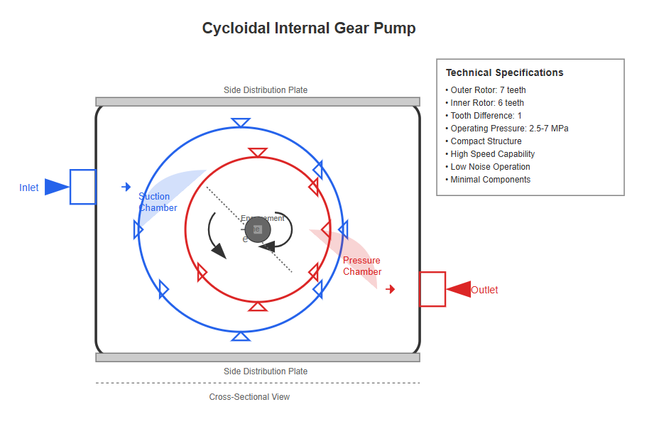
Cycloidal internal gear pump with inner and outer rotors
Cycloidal internal gear pumps feature an outer rotor and inner rotor with a one-tooth difference, eliminating the need for an intermediate crescent plate. The inner and outer rotor axes maintain an eccentricity (e), with the inner rotor serving as the driving element.
The rotors and side distribution plates form sealed volumes, with the rotor meshing line dividing these into suction and pressure chambers. During inner rotor rotation, the left sealed volume increases (suction chamber) while the right sealed volume decreases (pressure chamber).
Screw pumps essentially represent a specialized form of external meshing cycloidal gear pumps. Classification by screw number includes single-screw, twin-screw, three-screw, four-screw, and five-screw configurations. Cross-sectional profiles include cycloidal, cycloidal-involute, and circular arc tooth forms.
A typical three-screw pump contains three parallel, intermeshing double-threaded screws within the pump casing. The central convex screw serves as the driving element, while upper and lower concave screws function as driven elements.
The screws' outer circles maintain precise fit with corresponding casing arc surfaces, and meshing lines between driving and driven screws divide the helical grooves into multiple isolated, non-communicating sealed working chambers.
As the drive shaft rotates, these sealed working chambers form sequentially at the left end and progressively move rightward, eventually disappearing at the right end. Each complete revolution of the driving screw advances each sealed working chamber by one lead distance.
Larger screw diameters and deeper helical grooves increase pump displacement. Longer screws provide more sealing stages between suction and discharge ports, improving sealing effectiveness and enabling higher rated pressures.
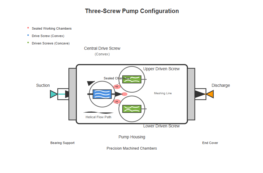
Three-screw pump showing fluid flow through helical chambers
Compared to other positive displacement hydraulic pumps, screw pumps offer a unique set of characteristics that make them suitable for specific applications:
Small size and light weight relative to displacement capacity
Excellent self-priming capability with high suction lift
Pulsation-free flow and extremely low noise levels
Reduced sensitivity to fluid contamination compared to other designs
Gentle meshing action reduces wear and extends operational life
Effective operation with high-viscosity fluids and particle-laden liquids
The primary limitations of screw pumps involve complex manufacturing processes and stringent precision requirements, restricting broader application. The close tolerances required between mating components necessitate specialized machining equipment and expertise. However, ongoing technological advancement continues to address these challenges, expanding the practical deployment of screw pump technology in applications such as precision machine tools, marine systems, and heavy industrial equipment.
Modern gear pumps incorporate sophisticated materials addressing traditional limitations. Advanced alloys and composites improve wear resistance and extend operational life, while specialized coatings reduce friction and enhance efficiency.
Advanced manufacturing techniques enable tighter tolerances, reducing internal leakage and improving volumetric efficiency. Computer numerical control (CNC) machining and precision grinding ensure optimal gear meshing characteristics.
Temperature management systems in high-performance gear pumps address heat generation from internal friction and fluid compression. Integrated cooling passages maintain optimal operating temperatures.
Contamination tolerance represents a significant advantage of gear pumps in industrial applications. Unlike other pump types requiring extensive filtration, gear pumps demonstrate remarkable resilience to particulate contamination.
This characteristic makes them particularly suitable for mobile hydraulic applications where maintaining fluid cleanliness presents challenges. The robust design of gear pumps allows them to continue operating despite moderate levels of contamination that might disable other pump types.
Modern designs incorporate enhanced contamination resistance through optimized clearances, hardened components, and improved filtration integration, further extending their operational life in challenging environments.
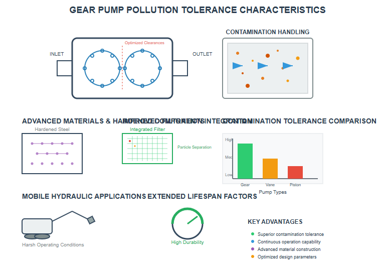
Modern gear pump with advanced materials and precision manufacturing
The evolution of gear pumps continues through material science advances, manufacturing innovation, and design optimization. These developments promise to expand the capabilities and applications of gear pump technology in the coming years.
Composite materials offer potential weight reduction while maintaining strength requirements. Carbon fiber reinforced polymers and advanced ceramics provide superior wear resistance and corrosion protection, extending pump life in aggressive environments.
Additive manufacturing technologies enable complex internal geometries previously impossible with conventional machining. This potentially revolutionizes pump design by allowing optimized flow paths, integrated features, and lightweight structures.
Integration of sensors monitoring pressure, temperature, flow, and vibration parameters enables predictive maintenance. Real-time data analysis prevents unexpected failures and optimizes system performance through IoT connectivity.
Development of gear pumps compatible with biodegradable fluids and synthetic alternatives to traditional hydraulic oils continues. Energy efficiency improvements reduce power consumption while meeting stringent environmental regulations.
As these technologies mature, gear pumps are finding new applications in renewable energy systems, precision automation, and mobile equipment. Their inherent reliability and efficiency make them particularly well-suited for offshore wind installations, solar power systems, and electric vehicle hydraulic subsystems.
The ongoing miniaturization of gear pump technology is also enabling their use in medical equipment, laboratory automation, and small-scale industrial systems where compact size and low noise operation are critical requirements.
Gear pumps remain fundamental components in hydraulic systems across diverse industries. Their simple yet effective design, combined with ongoing technological improvements, ensures continued relevance in modern applications. Understanding the operational principles, characteristics, and limitations of various gear pump configurations enables optimal selection for specific applications.
The balance between simplicity, reliability, and performance makes gear pumps attractive for applications ranging from mobile equipment to industrial machinery. While limitations exist, particularly regarding pressure capabilities and flow pulsation, continuous development addresses these challenges through innovative design solutions and advanced manufacturing techniques.
As hydraulic systems evolve toward higher efficiency, reduced environmental impact, and enhanced reliability, gear pumps adapt through material advances, design optimization, and integration with smart technologies. This evolution ensures gear pumps will continue serving critical roles in fluid power transmission for decades to come, maintaining their position as essential components in hydraulic system design and implementation.