
If you run a construction business, manage a fleet of vehicles, or rely on heavy machinery in your daily operations, the engine is just one part of the overall power.
It is one of the most important critical transmission systems in machines, converting the engine’s mechanical power into controlled and powerful hydraulic energy. Similar to mechanical or electrical drive systems, hydraulic transmission systems also differ in their structure and control strategies. However, they are always based on fundamental hydraulic circuits, each fulfilling a specific function within the system.
When evaluating the performance of hydraulic systems from a technical and component-oriented perspective, the focus goes far beyond mere power output. Important aspects include cycle speed, the coordination of complex movements (such as simultaneously raising the boom and rotating the upper structure), and, crucially, energy efficiency and fuel consumption control.
From the perspective of hydraulic system design and component manufacturing, high-performance hydraulic systems for construction machinery don’t pursue a single indicator but require consideration of several critical design priorities. These priorities include: reliability under variable and impact loads, integrated safety and pressure protection measures, effective thermal management and protection of sensitive hydraulic components, reliable filtration for graded operating conditions, an advanced control architecture for precise drives, and the ability to maintain efficiently and operate long-term.
Understanding the different hydraulic system types used in excavators is therefore not merely theoretical. From a systems engineering perspective, many performance limitations and reliability issues can be traced back to discrepancies between system architecture and component selection. Understanding the core system design is crucial for the development, selection, and adaptation of hydraulic components and system solutions.
Single-bucket hydraulic excavators are fundamental machines in earthmoving sectors such as building construction, transportation, water management, and open-pit mining. Its functional structure comprises the working attachment, the swing mechanism, and the undercarriage.
The working attachment consists of the boom, stick, and a range of interchangeable attachments such as the front bucket, rear bucket, and grapple. The operation of an excavator follows a defined work cycle, which is summarized below:
| Operation | Description |
|---|---|
| Digging | In hard soil, stick movement is the primary action, with the bucket cylinder adjusting the cutting angle. In softer soil, the bucket cylinder plays a more dominant role. For specialized applications, compound movements of the bucket, stick, and boom cylinders are used to control the digging trajectory. |
| Full-Bucket Lift & Swing | Digging concludes as the bucket cylinder extends and the boom cylinder lifts the load. Simultaneously, the swing motor rotates the upper structure toward the unloading position. |
| Dumping (Unloading) | The upper structure stops at the unloading point. The stick cylinder adjusts the unloading radius, and the bucket cylinder retracts to release material. The boom cylinder may assist when unloading height or positioning accuracy is required. |
| Return | After unloading, the upper structure reverses direction. The boom and stick cylinders coordinate to return the empty bucket to the next digging position. |
Each phase of this cycle imposes distinct requirements on hydraulic flow distribution, pressure control, and response characteristics, directly influencing system architecture and component specification.
Excavator hydraulic systems are commonly differentiated based on main pump configuration, displacement control method, power regulation strategy, and circuit arrangement. In practical equipment design, these factors directly influence controllability, efficiency, heat generation, and the technical requirements for key hydraulic components.
Common systems include fixed displacement systems (single, dual, or multi-pump), variable displacement systems with partial or full power regulation, and fixed–variable hybrid configurations. In practice, however, the two most common designs are the dual-pump, dual-circuit fixed displacement system and the dual-pump, dual-circuit full power variable displacement system.
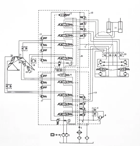
A representative example of this traditional architecture can be found in older full-hydraulic excavators such as the WY-100 model, which features approximately a 1 m³ bucket capacity. This system employs two fixed displacement pumps supplying two separate circuits, using series flow paths combined with manual flow merging.
| Circuit Type | Explanation and Component Function |
|---|---|
| Pump Allocation | Hydraulic Pump 1 supplies the swing motor, left travel motor, bucket cylinder, and auxiliary cylinders. Hydraulic Pump 2 supplies the boom cylinder, stick cylinder, right travel motor, and the dozer blade cylinder. |
| General Operation | Single Action: Actuating a control lever shifts the corresponding directional valve, isolating the unloading circuit and directing oil to the actuator. Return oil flows through the multi-way valve and speed-limiting valve (12) to the return main line (B). Series Supply: When multiple levers are actuated simultaneously, valve spools shift accordingly. Oil enters the first actuator, and its return flow becomes the inlet for the next actuator in series until returning to the main line. |
| Merging Circuit | The merging valve (16), normally de-energized and acting as a flow divider, enables flow combination when energized. It redirects oil from Pump 1 into Pump 2’s circuit, merging output from both pumps to increase actuator speed—typically for the boom or stick—while improving engine power utilization. |
| Speed Limiting & Regulation | Return oil from both valve banks passes through the speed-limiting valve (12) to the return main line (B). This pilot-controlled throttle valve primarily limits travel speed during downhill operation to prevent runaway and does not restrict flow during digging. |
| Back Pressure Circuit | A low-pressure circuit (115–200 psi or 0.8–1.4 MPa) provides forced makeup oil for the travel and swing motors to maintain internal contact conditions, while also supplying pressure for pilot control functions. |
| Preheating Circuit | Low-pressure warm oil is drawn from the back-pressure line and routed through a damper (5) into motor casings. This continuous circulation flushes wear particles and preheats the motors under cold conditions, preventing thermal shock caused by uneven expansion. |
| Filtration | The main return line passes through the oil cooler and a primary filtration assembly with magnetic and paper elements before returning to the tank. Leakage oil from motors and valve banks is routed through separate lines with small magnetic filters. |
This system architecture, widely used in modern small and medium-sized excavators, employs two variable-displacement axial piston pumps (typically with a bent shaft) in combination with an advanced three-position, six-way hydraulic multi-way valves. This design prioritizes efficiency, controllability, and the ability to perform multiple functions simultaneously; it demands the highest precision from the pumps, regulators, and control valves.
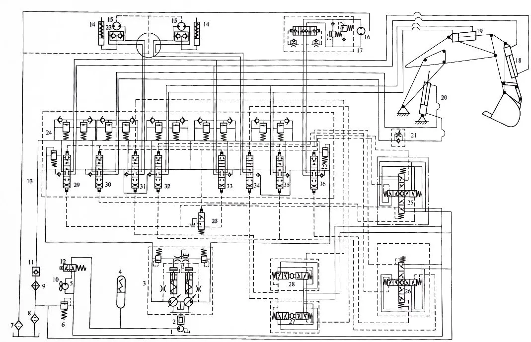
The heart of this system is the combined governor (3), which hydraulically connects the regulators of the two pumps. This configuration ensures that the total power consumption of both pumps is automatically adjusted to the available engine power.
Benefits: Maximum utilization of engine power. Under certain operating conditions, one pump can temporarily draw a greater share of available power if the other pump is lightly loaded.
Note: Because the power distribution between the two pumps can be uneven, one pump may temporarily operate near its load limit, which can reduce its service life if it is not properly calibrated.
Automatic flow merging is commonly applied to functions such as bucket digging and boom lifting, allowing both pumps to deliver oil simultaneously. In contrast, when boom lowering or swing reversal, only a single pump is typically used for hydraulic supply to minimize throttling losses and heat generation.
Each main pump circuit is protected by a full-flow pressure relief valve (22) with a typical opening pressure of approximately 25 MPa (3,600 psi). Each actuator line is equipped with a load-holding safety valve (24) with a typical opening pressure of approximately 30 MPa (4,350 psi) to absorb pressure spikes during braking or directional changes.
The swing motor (16) features an integrated hydraulic brake (17) that ensures controlled stopping and stable deceleration. The travel motor (15) uses a normally closed hydraulic brake cylinder (14) that is released via pilot pressure through a shuttle valve when system pressure exceeds a defined threshold (e.g., 500 psi or 3.5 MPa).
A dedicated gear pump (1) supplies oil to the fan motor (5), which drives the air-cooled oil cooler (9). The cooler’s system is controlled by a temperature sensor and a solenoid valve (12) in the hydraulic oil tank. This ensures that the cooling system is only activated when the oil temperature exceeds a defined limit. This saves engine power and improves cold-start efficiency.
The large hydraulic multi-way valve is controlled by four manually reducing pilot valves (25–28), which also serve as the operator interface. Universal-joint joysticks (25, 26) actuate the control valves for the boom, stick, bucket, and swing functions, while separate pilot valves (27, 28) control the travel motor.
Pulling the control lever proportionally reduces the pressure of the pilot pump, typically in the range of 200–435 psi (1.4–3 MPa).The resulting secondary pressure, varying from 0–360 psi (0–2.5 MPa), is directly proportional to lever displacement, enabling precise and predictable control. Operating forces remain low, typically not exceeding 30 N, which increases operator comfort and reduces fatigue.
For original equipment manufacturers (OEMs) and operators of heavy equipment, switching to dual-pump full-power variable displacement systems significantly improves efficiency but also increases the reliance on precision hydraulic components. Elements such as the combination regulator, variable axial piston pumps, and pilot control valves are particularly sensitive to wear and calibration accuracy.
From a technical perspective, performance problems such as response delays or reduced travel speeds are often due to wear in the pilot circuit or minor calibration errors in load sensing or power control. These conditions highlight the importance of high-precision hydraulic spare parts and system-specific calibration rather than generic replacements.
Although full power variable systems are designed to support simultaneous pump operation—beneficial for synchronized track movement—the uneven power distribution characteristic of these systems means that standard replacement components may not always align optimally with engines that have accumulated significant operating hours. In such cases, customized pump power curves and finely tuned control valve spool designs can improve performance stability and component longevity.
For original equipment manufacturers (OEMs) or fleet operators looking to optimize excavator hydraulic performance beyond standard catalog parts, system-specific hydraulic customization is a practical and effective approach. This involve include tailored component design, calibration support, or integrated subsystem solutions aligned with actual operating conditions.
A comprehensive understanding of excavator hydraulic system architecture—from the series circuits of traditional fixed displacement designs to the full power regulation strategies of modern variable displacement systems—is the technological foundation for effective component selection and system optimization.
By collaborating with partners who understand the stringent tolerances and control requirements of modern hydraulic systems and can offer high-quality hydraulic spare parts and customized solutions, equipment manufacturers and operators achieve greater efficiency, more responsive behavior and a longer service life under a wide variety of operating conditions.
For intricate hydraulic component and system design consulting tailored to the specific needs of excavators, we will be your partner in precision engineering.