
Last month a maintenance supervisor in Texas emailed us a photo of a spool valve he’d pulled from a Komatsu loader. “Scored lands, internal leakage, cylinder drifting under load—what went wrong?” He’d been running the machine for two years without changing the return-line filter. The spool surface looked like someone had dragged sandpaper across it.
That conversation happens in our office at least twice a week. And it almost always starts the same way: someone is dealing with a directional control valve problem they didn’t see coming, because they didn’t fully understand what the valve was doing inside their circuit in the first place.
This guide is our attempt to fix that. Not the Wikipedia version—the version we wish every customer read before something went wrong.
A directional control valve (DCV) is the decision-maker inside a hydraulic system. It decides which actuator gets oil, in which direction, and when. Every time an excavator boom lifts, a press ram extends, or a log splitter cycles—a DCV shifted to make that happen.
Take away the DCV, and you’ve got a pump pushing oil into a dead end. No motion. No work. Just heat.
We’ve disassembled thousands of these in our factory in Shenzhen. Here’s what you see when you crack one open:
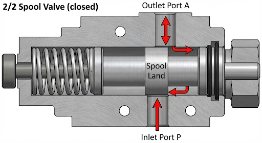
A precision-ground steel spool sits inside a matching bore in the valve body. The spool has lands (raised cylindrical sections) and undercuts (recessed grooves). The lands act as plugs, blocking flow passages. The undercuts act as bridges, connecting passages together. When you shift the spool—even by just a few millimeters—you change which passages are blocked and which are connected.
That’s it. That’s the entire principle. Everything else is just variations on which passages connect to what, and how you move the spool.
Simplified cross-section of a 4/3 spool valve. In our production line, spool-to-bore clearances run 5–15 μm (microns)—tighter than a human hair.
Here’s the operating sequence as we explain it to our OEM customers:
The whole cycle takes 20–50 milliseconds on a solenoid valve. That snap-action is why old-timers call these “bang-bang” valves—you can literally hear the spool hit its stop.
This is where we spend the most time on support calls. Customers focus on port count and flow rating—both important—but the center condition determines how the entire system behaves when nobody’s touching the controls.
| Center Type | What Happens at Neutral | Best For | Watch Out For |
|---|---|---|---|
| Closed | All ports blocked. Actuator locked in position. | Cranes, lifts, anything holding a load | Pump deadheads → relief valve must be set correctly or you’ll overheat |
| Open | P→T open. Work ports blocked. Pump unloads to tank at low pressure. | Single-function circuits, fixed-displacement pump systems | No load-holding ability at neutral. Cylinder can drift under external force. |
| Tandem | P→T open, A & B blocked. Pump unloads while actuator holds position. | Multi-section stacks sharing one pump | Confused constantly with open center—check your circuit drawing |
| Float | A & B connected to tank. Pump blocked. Actuator moves freely. | Dozer blades following ground contour, wheel motors during towing | Zero load holding. Blade or boom will drop under gravity. |
If you’re building a new system or retrofitting an existing one, our custom hydraulic design team can review your circuit and recommend the correct center condition. It’s a free consultation—and it prevents the kind of headache that Indonesian customer went through.
The actuation method you choose ripples through the entire system—affecting cost, response time, automation capability, and failure modes. Here’s how they compare in practice, based on what we see across our customer base:
| Method | Response Time | Max Flow Rating | Automation? | Where We See It Most |
|---|---|---|---|---|
| Manual lever | Depends on operator | Up to ~300 LPM | No | Farm tractors, small loaders, log splitters |
| Solenoid (direct) | 20–50 ms | ~80 LPM typical | Yes (PLC, relay) | Industrial presses, packaging lines, test rigs |
| Solenoid pilot | 50–150 ms | 300+ LPM | Yes | Excavators, mining gear, marine winches |
| Mechanical (cam/roller) | Tied to machine RPM | Varies | Semi (sequence-based) | Automated production lines, transfer machines |
Standard DCVs have a binary personality—fully open or fully closed, nothing in between. That works fine for a log splitter. It does not work for a 40-ton excavator trying to feather a bucket into a trench without overshooting.
Proportional directional valves solve this by allowing the spool to stop anywhere between its end positions. A variable-current solenoid nudges the spool incrementally; metering notches on the spool lands translate spool position into a controlled flow rate. The result: the operator controls both direction and speed from one valve.
In field tests we’ve run on customer machines, proportional valves cut hydraulic cycle times by roughly 10–20% compared to discrete valves paired with separate flow control valves—mainly because eliminating those extra flow controls removes their parasitic pressure drops. For a deeper technical comparison, our article on excavator main control valve types walks through open center vs. load sensing vs. negative flow control with real efficiency data.
We track every warranty return. After 25 years and tens of thousands of units shipped, the failure pattern is painfully consistent:
| Failure Cause | % of Returns | What Happens | Prevention |
|---|---|---|---|
| Particle contamination | ~60% | Scored spool lands → internal leakage → actuator drift | Return-line filtration to ISO 18/16/13. Change elements on schedule. |
| Overheating (>80 °C) | ~18% | Seal degradation → external leaks, sticky spool | Adequate cooling. Check oil cooler fan and thermostat. |
| Water in oil (>0.1%) | ~12% | Micro-corrosion on spool surface → erratic shifting | Desiccant breathers. Keep reservoir sealed. |
| Solenoid burnout | ~8% | Valve stuck in last shifted position | Verify supply voltage. Check connector tightness annually. |
| Incorrect spool/center | ~2% | System works but performance is wrong | Verify part number against circuit schematic before install. |
Cold weather adds its own layer of risk. Oil viscosity doubles or triples below 0 °C, and that thick oil can stall pilot circuits completely. We covered this in detail in Cold Weather Hydraulics: How to Protect Your System—worth reading if you run equipment through winter.
Every valve creates a pressure drop as oil passes through it. That drop wastes energy—converted to heat—and reduces the pressure available at the actuator. In our lab, we measure pressure drop across every valve model we produce. Here’s what typical numbers look like at rated flow:
| Valve Type | Flow @ Rated | ΔP (P→A Path) | ΔP (B→T Path) |
|---|---|---|---|
| Cetop 3 / NG6 solenoid DCV | 60 LPM | 8–12 bar | 5–8 bar |
| Cetop 5 / NG10 solenoid DCV | 120 LPM | 6–10 bar | 4–7 bar |
| Monoblock manual DCV (P80 type) | 80 LPM | 10–15 bar | 6–10 bar |
| Proportional DCV (NG10) | 100 LPM | 12–18 bar | 8–12 bar |
Why does this matter? If your system runs at 200 bar and you’re losing 15 bar across the DCV, that’s 7.5% of your working pressure gone before the oil even reaches the cylinder. Stack two or three valves in series and you can easily lose 20–30 bar—enough to noticeably slow actuator speed under heavy load. Oversizing the valve one frame up (say, NG10 instead of NG6) costs a bit more upfront but recovers that pressure and often pays for itself in reduced cycle times.
A 2-way valve has two ports—in and out—and simply stops or allows flow, like a gate. A 4-way valve has four ports (pressure, tank, and two work ports) and can route oil to either side of a double-acting cylinder, enabling full extend-retract control. Almost every mobile and industrial hydraulic circuit uses some form of 4-way valve.
The earliest sign is usually actuator drift under load—the cylinder slowly creeps when it should be holding position. Other symptoms include sluggish movement, excessive heat at the valve body, and unusual noise during shifting. If you’re seeing these, the spool lands are likely scored and internal leakage is bypassing the work ports. Our spare parts catalogue stocks over 7,000 components including replacement spools, seals, and complete valve assemblies for fast turnaround.
No. Hydraulic systems typically operate at 200–350 bar; pneumatic systems run at 6–10 bar. The housings, seals, and spool tolerances are completely different. Using a pneumatic valve on hydraulic pressure is a safety hazard.
Usually contamination—particles wedge between the spool and bore. Less commonly: varnish buildup from overheated oil, a swollen seal from fluid incompatibility, or a burned-out solenoid coil that can no longer generate enough force to overcome spring return. In our experience, 90% of “stuck valve” calls trace back to dirty oil.
Neither is universally better. Open center is simpler and keeps the pump unloaded at idle (less heat), but it cannot hold a load at neutral. Closed center holds loads but requires a properly set relief valve to protect the pump when the valve is centered. The right choice depends on your circuit design, pump type, and application.
Both refer to standardised mounting interface sizes. Cetop 3 = NG6 (6mm nominal), Cetop 5 = NG10 (10mm nominal). The number roughly indicates the maximum flow capacity the valve body can handle efficiently. Choosing the right frame size is critical—see the pressure drop table above.
Send us your checklist or circuit schematic. Our engineers will recommend a valve matched to your application—no guesswork, no overselling.
Directional control valves aren’t complicated once you understand the spool. Lands block. Undercuts connect. Shift the spool, redirect the oil, move the load. Everything else—center configuration, actuation method, proportional control—is about making that basic mechanism fit your specific application.
What is complicated is getting all the details right: the center type that matches your circuit, the frame size that keeps pressure drop low, the filtration that keeps spool surfaces clean for 10,000 hours instead of 2,000. That’s where 25 years of building, testing, and troubleshooting these valves gives us something a datasheet can’t—and it’s why customers in over 100 countries trust POZOOM Hydraulic to get it right the first time.
