
Hydraulics pumps don’t actually create pressure. They generate flow by moving fluid from a reservoir through a system, and pressure builds only when that flow encounters resistance from a load, valve, or other restriction. This mechanical action creates a vacuum at the pump inlet, allowing atmospheric pressure to push fluid into the pump, which then delivers it to the hydraulic system where resistance transforms flow into pressure.
The core function of a hydraulics pump involves two coordinated actions that work together to move fluid through a system. When the pump’s mechanical elements begin moving, they create a partial vacuum at the inlet port. This vacuum doesn’t exist in isolation—it serves a specific purpose in the fluid movement chain.
Atmospheric pressure acting on the fluid in the reservoir responds to this vacuum by forcing liquid through the inlet line and into the pump chamber. Think of it like drinking through a straw: the vacuum you create doesn’t pull the liquid up, rather atmospheric pressure on the liquid’s surface pushes it toward the lower pressure area in the straw.
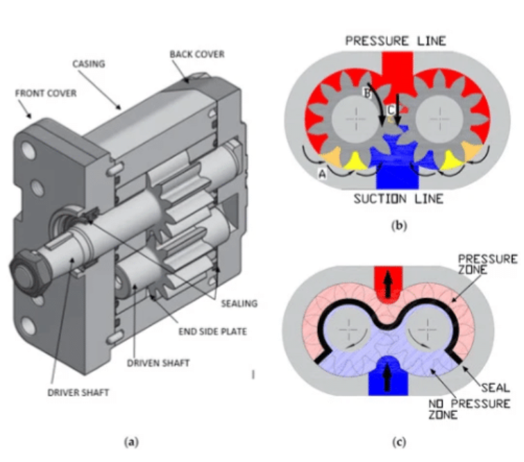
The pump’s mechanical components then capture this incoming fluid and physically move it toward the outlet port. In a gear pump, meshing teeth trap fluid in the spaces between them and carry it around the pump housing. In a piston pump, reciprocating pistons draw fluid in during the intake stroke and force it out during the compression stroke. In a vane pump, sliding vanes create expanding and contracting chambers that accomplish the same fluid movement.
This displacement happens continuously as long as the pump operates. The rate of displacement determines flow rate, measured in gallons per minute or liters per minute. A pump rated at 10 GPM will theoretically move 10 gallons of fluid every minute, assuming minimal internal leakage.
Here’s where the common misconception gets corrected. If you disconnect a pump from any load and let it pump into an open container, you’ll measure very little pressure at the outlet—perhaps just enough to overcome the resistance of moving through the hoses. The pump is working perfectly and moving its rated flow, but without resistance, no significant pressure develops.
Pressure emerges when flowing fluid meets something that restricts or opposes that flow. In a hydraulics system, this resistance comes from several sources. A hydraulics cylinder trying to lift a 5,000-pound load creates substantial back-pressure. Control valves that regulate flow direction create restrictions. Even the friction of fluid moving through hoses and fittings contributes minor resistance.
Pascal’s Law governs what happens next. When pressure develops at one point in an enclosed fluid system, it transmits equally throughout that fluid in all directions. If resistance at a cylinder creates 2,000 PSI of back-pressure, that same 2,000 PSI appears throughout the fluid column, including back at the pump outlet.
The pump must generate enough force through its mechanical displacement to overcome this resistance and continue moving fluid. A pump rated for 3,000 PSI maximum pressure can handle systems where resistance builds up to that level. Beyond that threshold, either a relief valve opens to prevent damage, or something in the system fails.
The relationship between pressure and load follows a straightforward calculation. Pressure equals force divided by area (P = F/A). A 3-inch diameter cylinder has roughly 7 square inches of surface area. To lift 14,000 pounds, the system needs to develop 2,000 PSI (14,000 ÷ 7 = 2,000). The pump doesn’t “decide” to create 2,000 PSI—the load resistance forces that pressure level, and the pump either handles it or doesn’t.
Most hydraulics pumps operate on positive displacement principles, which fundamentally shapes how they interact with system resistance. A positive displacement pump moves a fixed volume of fluid with each rotation or stroke of its pumping elements. This volume remains nearly constant regardless of outlet pressure, within the pump’s pressure rating.
The tight tolerances between moving elements and the pump housing make this possible. In an external gear pump, the clearance between gear teeth and the housing might be just a few thousandths of an inch. This tight fit prevents fluid from slipping backward from the high-pressure outlet to the low-pressure inlet.
Some internal leakage always occurs—it’s physically impossible to eliminate completely. A healthy pump might lose 2-3% of its theoretical displacement to internal bypass. As pumps wear, these tolerances open up and leakage increases. A pump slipping 15% of its flow internally isn’t building adequate pressure not because it can’t, but because too much flow escapes back to the inlet instead of reaching the outlet.
This characteristic creates an important safety consideration. If you completely block the outlet of a positive displacement pump while it continues running, pressure will build instantaneously to whatever level the pump and drive system can withstand. Without a relief valve to dump excess flow, something will break—either the pump housing, a hose, or the drive shaft. This explains why every hydraulic system requires properly set pressure relief protection.
Three main pump types dominate hydraulics applications, each using distinct mechanical methods to achieve fluid displacement.
Gear pumps represent the simplest and most economical design. Two intermeshing gears rotate inside a close-fitting housing. As the gears unmesh at the inlet side, expanding volume creates the vacuum that draws in fluid. The teeth trap fluid in the spaces around the gear perimeter and carry it to the outlet side, where the meshing action forces it out under pressure. External gear pumps typically handle pressures up to 3,000-3,500 PSI, with some high-pressure designs reaching 5,000 PSI. They’re reasonably efficient at 85-92%, relatively tolerant of contaminated fluid, and produce moderate noise levels.
Vane pumps use a different approach. A slotted rotor spins inside an elliptical housing, with spring-loaded vanes sliding in and out of the rotor slots. As the rotor turns, centrifugal force and spring pressure keep the vane tips in contact with the housing wall. The elliptical shape means chambers between vanes expand on one side (inlet) and contract on the other (outlet), creating the pumping action. These pumps deliver smooth flow with less pulsation than gear pumps, operate more quietly, and typically achieve 88-93% efficiency. Pressure capabilities range from 2,000-3,000 PSI for most designs, though some industrial models reach higher.
Piston pumps achieve the highest pressures and efficiencies but with greater complexity and cost. Axial piston pumps arrange multiple pistons in a circular pattern within a cylinder block. A swashplate or bent axis design causes the pistons to reciprocate as the cylinder block rotates, each piston drawing in fluid during its extension stroke and pumping it out during compression. Radial piston pumps position pistons around a central eccentric cam that drives their reciprocating motion. These designs routinely operate at 5,000-10,000 PSI, with some specialized units handling 15,000 PSI or more. Efficiencies typically reach 92-98%, making them ideal for applications demanding high pressure or precise control.
Understanding how pressure and flow interact reveals important practical insights for system operation and troubleshooting. These two parameters aren’t independent—they constantly influence each other through the physics of fluid dynamics and system design.
When a system operates at higher pressures, hydraulics pumps experience greater internal leakage as fluid finds more incentive to slip through clearances. A gear pump might maintain 10 GPM flow at 1,000 PSI but drop to 9.2 GPM at 3,000 PSI as internal bypass increases. This explains why pump manufacturers specify flow rates at specific pressures.
System components also contribute resistance that increases with flow rate. Fluid moving faster through hoses, fittings, and valves encounters more friction. Double the flow rate and you typically quadruple the pressure drop across these restrictions. A system designed with undersized lines might struggle to achieve rated pressures simply because excessive flow resistance “steals” pressure before it reaches the actuators doing work.
Temperature affects this relationship too. Hot oil flows more easily, reducing pressure drops through restrictions but also increasing internal pump leakage. Cold oil behaves oppositely—it creates higher pressure drops in lines but leaks less through pump clearances. Systems need to account for this variation, particularly in mobile equipment operating across wide temperature ranges.
Variable displacement pumps add another dimension. These designs can alter their displacement per revolution based on system demands. When pressure reaches a set point, a compensator mechanism reduces pump displacement, decreasing flow output while maintaining pressure. This allows the system to hold a load with minimal energy waste, unlike fixed displacement pumps that continue pumping full flow over a relief valve.
Systems experiencing pressure issues rarely fail because the pump suddenly stopped “making pressure.” More often, the root cause involves flow paths or resistances that changed, altering how the pump’s flow converts to pressure.
A cylinder moving slower than normal often indicates inadequate flow reaching it. Internal pump wear increases bypass, reducing the effective flow available. External leaks—burst hoses, blown seals, or damaged fittings—create parallel paths for fluid to escape rather than doing work. Stuck or incorrectly adjusted valves might direct flow elsewhere. In each case, the pump generates its rated flow, but system problems prevent that flow from creating appropriate pressure at the work point.
Cavitation produces dramatic symptoms when hydraulics pumps can’t receive adequate inlet flow. The pump’s displacement action creates a vacuum at the inlet as designed, but if restrictions block the supply line or the reservoir runs low, the vacuum becomes severe enough to vaporize the hydraulic fluid. These vapor bubbles collapse violently on the pressure side, creating a characteristic whining or grinding noise while damaging internal pump surfaces through repeated implosion impacts. Contaminated suction strainers, kinked supply lines, or inlet plumbing that’s too small all contribute to cavitation.
Overheating often accompanies pressure problems. A relief valve dumping excess flow back to tank converts all that hydraulic energy to heat. A pump running at 10 GPM and 2,500 PSI while the relief valve set at 2,500 PSI stays cracked open is wasting about 16 horsepower as heat. The fluid temperature climbs, viscosity drops, leakage increases, and efficiency falls further in a deteriorating cycle.
Contamination remains the leading killer of hydraulics pumps. Particles entering the system—through breathers, past worn cylinder seals, or from improper maintenance—act as abrasives between moving parts. Piston pumps suffer most from contamination due to their tight tolerances; even fine particles jam between pistons and bores. Gear pumps tolerate dirty fluid better thanks to looser clearances, but eventually contamination wears away the precision fits that prevent internal leakage.
Selecting appropriate system pressure involves balancing multiple factors beyond just the load requirements. Higher pressure systems generate more force from smaller actuators, reducing weight and physical size. A cylinder operating at 3,000 PSI can be significantly smaller than one handling the same load at 1,500 PSI, saving space and cost on the actuator itself.
However, higher pressures demand more robust components throughout. Hoses, fittings, valves, and seals rated for 5,000 PSI cost considerably more than 2,000 PSI equivalents. Hydraulics pumps capable of higher pressures are more expensive and often less efficient at lower operating pressures. The entire system must be engineered to safely contain and control these forces.
Industrial fixed equipment typically operates at 1,500-3,000 PSI as a practical middle ground. This range delivers good power density while using reasonably priced components. Mobile equipment like construction machinery often runs higher, 3,000-5,000 PSI, where size and weight constraints justify the premium components. Aircraft hydraulics systems push even further to 5,000-8,000 PSI where every pound of system weight matters enormously.
Matching the pump to the system’s actual needs prevents waste. An oversized pump moving excessive flow over a relief valve accomplishes nothing except generating heat and consuming power. An undersized pump makes the system sluggish or unable to achieve necessary speeds. Careful calculation of actuator volumes, cycle times, and simultaneous operations determines the required flow rate, while load calculations establish necessary pressure.
Relief valves must be set carefully, typically 10-15% above normal operating pressure but well below component ratings. This margin allows for pressure spikes from load impacts or valve transitions while protecting against catastrophic failures. The relief valve becomes the system’s pressure limit—not the pump’s capability.
While pressure gets most attention in these discussions, flow rate determines how quickly actuators move and how much work gets accomplished. A pump’s flow rating, measured in gallons or liters per minute, directly controls cycle times and productivity.
Fixed displacement hydraulics pumps deliver constant flow at a given speed. Run the pump faster and flow increases proportionally; slow it down and flow decreases. This simplicity works well for applications with consistent demands, but wastes energy during low-demand periods since the pump continues pushing full flow.
Variable displacement designs adjust internal geometry to match changing requirements. When an actuator stops moving and pressure rises to the compensator setting, the pump automatically reduces displacement to just enough flow to maintain pressure against small leakages. This saves substantial energy compared to dumping excess flow over a relief valve, though the pumps themselves cost more.
Multiple pump systems—using several hydraulics pumps driven from one power source—can optimize efficiency further. A large pump handles heavy-demand periods while smaller pumps meet lighter loads. Some designs unload certain pumps completely during low-demand phases.
Flow velocity through hydraulic lines matters too. Fluid moving faster than 15-20 feet per second in pressure lines creates excessive friction losses and turbulence. Return lines should stay under 10 feet per second. These velocity limits often determine minimum line sizes, which then affect system packaging and cost. Undersized plumbing trying to move adequate flow creates unnecessary pressure drops that reduce system effectiveness.
A hydraulics pump generates flow by mechanically displacing fluid from the inlet to the outlet. Pressure develops as a consequence when this flow encounters resistance in the system. The pump itself doesn’t create pressure—the load, restrictions, and system design determine what pressure level emerges from the flow the pump produces.
In a positive displacement pump, blocking the outlet while the pump runs causes pressure to rise instantly until something fails. The pump continues trying to displace its rated volume with nowhere for the fluid to go. This is why hydraulics systems require properly sized relief valves—they provide a controlled release path before destructive pressure levels develop.
Gradual pressure loss typically indicates increasing internal wear. As clearances between moving parts open up, more fluid bypasses internally from the high-pressure outlet back to the low-pressure inlet. The pump moves its designed volume, but an increasing percentage takes this shortcut rather than exiting through the outlet port. Contamination accelerates this wear process significantly.
Simply installing a pump rated for higher pressure won’t increase system pressure. The load resistance determines what pressure develops. However, a higher-rated pump ensures the system can safely operate at increased pressures if loads demand it. You’d also need to verify that all other components—hoses, valves, cylinders—can handle the higher working pressure.
Hydraulic pumps accomplish their task through mechanical displacement of fluid, creating flow that transforms into pressure when meeting resistance. This principle underlies countless applications from construction equipment to aircraft systems. The pump’s job is moving fluid reliably; the system’s design and load conditions determine how that flow manifests as useful pressure to accomplish work. Understanding this distinction helps in selecting appropriate pumps, designing efficient systems, and diagnosing problems when they occur.