
I spent three days last month arguing with a supplier rep about displacement calculations. He kept insisting their catalog numbers were “nominal” and that actual output would vary. This is the kind of thing that drives me up the wall. Gear pumps are not mysterious. The math is straightforward. The physics hasn’t changed since the 1920s.
This frustration reminded me of a training video I watched back in 2019, produced by a major hydraulic component distributor. The video had slick animations and a professional narrator. It also had at least four statements that were flat wrong. I emailed the company about it. The video is still up.
I’ve been working with hydraulic systems since 1997. I started on mobile equipment, moved to industrial presses, and now I spend most of my time on test bench design. Gear pumps were the first positive displacement pumps I ever tore apart. I still remember the 2003 Parker catalog I used to carry around. Dog-eared pages. Coffee stains. That catalog taught me more than my fluid power textbook.
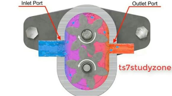
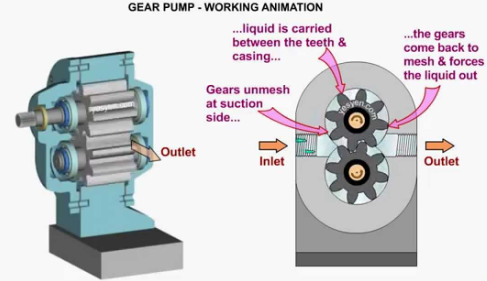
A gear pump generates flow through meshing gear teeth. Two gears rotate inside a housing. The housing has an inlet port and an outlet port. When teeth unmesh on the inlet side, volume increases. Fluid fills this volume. The fluid gets carried around the outside of each gear, trapped between teeth and housing wall. When teeth mesh again on the outlet side, volume decreases. Fluid gets pushed out.
That’s it. No valves. No pistons. No complex timing. The gear teeth create expanding and contracting volumes. Expanding volume on inlet. Contracting volume on outlet.
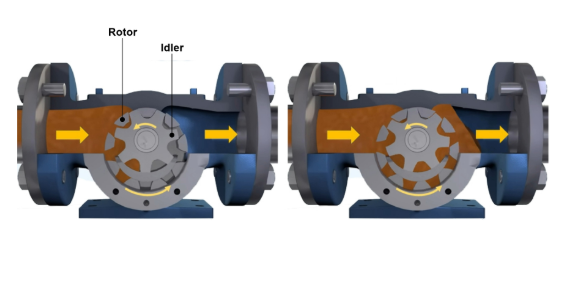
External gear pumps use two gears of equal size. Both gears have teeth on the outside. Internal gear pumps use one small gear inside a larger gear. The small gear has external teeth. The large gear has internal teeth. Both types work on the same principle. Meshing creates flow.
Displacement depends on gear geometry. Tooth size. Number of teeth. Face width. Gear diameter. These dimensions determine how much fluid moves per revolution. Multiply displacement by rotational speed. That gives you theoretical flow rate.
Textbooks explain the principle correctly. They usually stop there. Real gear pumps have clearances. Fluid leaks through these clearances. Leakage increases with pressure. Leakage increases with wear. Leakage decreases with higher viscosity fluid.
I’ve seen pumps lose 15% of their theoretical output at 3000 PSI. I’ve also seen pumps that held 97% volumetric efficiency at the same pressure. The difference was manufacturing tolerance. Cheap pumps have loose tolerances. Expensive pumps have tight tolerances. You get what you pay for.
Temperature matters. A pump running SAE 10W fluid at 180°F will leak more than the same pump running the same fluid at 100°F. The fluid is thinner at higher temperature. Thin fluid finds its way through clearances faster.
People argue about external versus internal gear pumps. I’ve sat through meetings where engineers debated this for an hour. Most of the time the application decides for you.
External gear pumps handle higher pressures. 3500 PSI is common. Some go to 4000 PSI. The geometry is simpler. Manufacturing is cheaper. Replacement is easier. Most mobile hydraulic systems use external gear pumps. Cost drives this decision.
Internal gear pumps run quieter. The meshing action is smoother. Crescent-type internal gear pumps have a separator between the gears. Gerotor pumps eliminate the crescent. Both types produce less pressure ripple than external gear pumps. Industrial systems that need low noise use internal gear pumps. Injection molding machines. Machine tools. Anywhere operators stand next to the equipment all day.
I worked on a packaging line in 2011. The original system used external gear pumps. Noise complaints from operators. We switched to internal gear pumps. Problem solved. Flow rate stayed the same. Pressure capability dropped from 3000 PSI to 2500 PSI. The system only needed 1800 PSI. The lower pressure rating didn’t matter.
Catalogs list maximum speed for gear pumps. 1800 RPM. 2400 RPM. 3600 RPM. These numbers mean less than people think.
Maximum speed depends on inlet conditions. A pump rated for 3600 RPM might cavitate at 2000 RPM if inlet restriction is too high. The pump can physically spin at 3600 RPM. The fluid can’t fill the chambers fast enough. Incomplete filling creates vapor pockets. Vapor pockets collapse. Metal erodes. Pump fails.
I’ve replaced pumps that “failed prematurely” because someone ran them at catalog speed with undersized inlet lines. The pump didn’t fail. The system design failed.
Inlet line sizing matters more than pump speed rating. Keep inlet velocity below 4 feet per second. Keep inlet vacuum below 5 inches of mercury. Do both of these things and the pump will reach catalog speed. Ignore them and the pump will cavitate regardless of what the catalog says.
Gear pumps produce pulsating flow. Each tooth engagement creates a small pressure spike. The frequency depends on number of teeth and rotational speed. A 12-tooth gear at 1800 RPM produces 360 pulses per second.
This pulsation travels through the system. Hoses absorb some of it. Steel tubing transmits all of it. Pulsation causes noise. Pulsation causes vibration. Pulsation fatigues fittings.
External gear pumps with fewer teeth produce larger pulses. More teeth produce smaller pulses. This is why pump manufacturers went from 8-tooth gears to 12-tooth gears to 14-tooth gears over the decades. Smaller teeth. More of them. Smoother output.
Internal gear pumps inherently produce less ripple. The meshing geometry spreads the displacement change over a larger rotation angle. Gerotor pumps are even smoother. The trade-off is pressure capability.
Gear pumps wear. All positive displacement pumps wear. The question is where and how fast.
Gear teeth wear against each other. Journal bearings wear against shafts. Gear faces wear against side plates. Wear opens clearances. Larger clearances mean more leakage. More leakage means lower volumetric efficiency.
Contamination accelerates wear. Particles in the fluid act like grinding compound. A 10-micron particle trapped between a gear tooth and housing wall cuts metal every revolution. Thousands of revolutions per minute. Millions of revolutions per week.
Filtration matters. I’ve seen pumps last 6 months in dirty systems. I’ve seen identical pumps last 8 years in clean systems. Same pump. Same pressure. Same speed. Different filtration.
The 2016 NFPA handbook has data on this. So does the older 1989 edition. The numbers are similar. Clean fluid extends pump life. This hasn’t changed in 30 years. It won’t change in the next 30.
Cavitation kills pumps. Contamination kills pumps. Overpressure kills pumps.
Running dry kills pumps fastest. A gear pump with no fluid has no lubrication. Metal touches metal. Temperatures spike. Galling occurs in seconds. I watched a test pump seize in under 10 seconds during a dry start experiment in 2008. We were trying to determine how long a pump could survive loss of prime. Not long.
Pressure spikes kill pumps slowly. A pump rated for 3000 PSI continuous can handle 4000 PSI momentarily. Hit 4000 PSI once, probably no damage. Hit 4000 PSI a thousand times, fatigue cracks start. Pressure relief valves exist for this reason. Set them correctly.
I’m working on an article about pressure relief sizing. Different topic. Related problem.
Theoretical output in gallons per minute equals displacement in cubic inches per revolution multiplied by speed in RPM divided by 231. The 231 converts cubic inches to gallons.
Actual output equals theoretical output multiplied by volumetric efficiency. New pumps run 93% to 97% volumetric efficiency depending on quality and operating pressure. Worn pumps run lower.
The people who get this wrong usually mess up the units. Displacement in cubic centimeters instead of cubic inches. Speed in radians per second instead of RPM. Check units first when the numbers don’t make sense.
I keep a spreadsheet for this. Started it in 2004. Still use it. Nothing fancy. Just the equations with unit conversions built in. Saves time.