
Hydraulic flow control valves represent a fundamental component in fluid power systems, serving as the primary mechanism for regulating fluid velocity and volume through hydraulic circuits. These sophisticated devices, often monitored by hydraulic flow meter instrumentation, enable precise control of actuator speeds in industrial applications ranging from manufacturing equipment to mobile machinery.
The integration of hydraulic flow meter technology with flow control valves has revolutionized system efficiency, achieving accuracy levels of ±0.5% in modern installations.
The fundamental principle underlying flow control valve operation involves the manipulation of orifice areas to modulate flow rates through the valve body. When coupled with hydraulic flow meter feedback systems, operators can achieve real-time monitoring and adjustment capabilities.
Statistical analysis from industrial implementations shows that systems incorporating hydraulic flow meter monitoring demonstrate 35% improved accuracy in flow regulation compared to non-monitored configurations.
±0.5%
In modern installations with flow meter integration
35%
In flow regulation accuracy with monitoring
42%
Reduction in unplanned maintenance events
The theoretical framework governing flow control valve operation centers on the fundamental flow equation:
Modern hydraulic flow meter technology enables continuous monitoring of these parameters, providing operators with comprehensive system performance data. Industrial surveys indicate that facilities utilizing hydraulic flow meter systems report 42% reduction in unplanned maintenance events through early detection of flow anomalies.
The throttling characteristics of flow control valves directly influence system stability and performance. Hydraulic flow meter measurements reveal that optimal throttling stiffness T, defined as:
This relationship demonstrates that smaller orifice areas and higher pressure differentials enhance flow stability. Field data collected through hydraulic flow meter installations shows that maintaining pressure differentials between 2.5-3.5 MPa yields optimal stability coefficients of 0.92-0.96.
Temperature compensation remains critical for maintaining consistent performance. Hydraulic flow meter readings indicate that temperature variations of ±20°C can alter flow rates by 8-12% in systems without compensation. Advanced hydraulic flow meter systems incorporate temperature sensors, enabling automatic compensation algorithms that maintain flow accuracy within ±1.5% across operating temperature ranges of -20°C to +80°C.
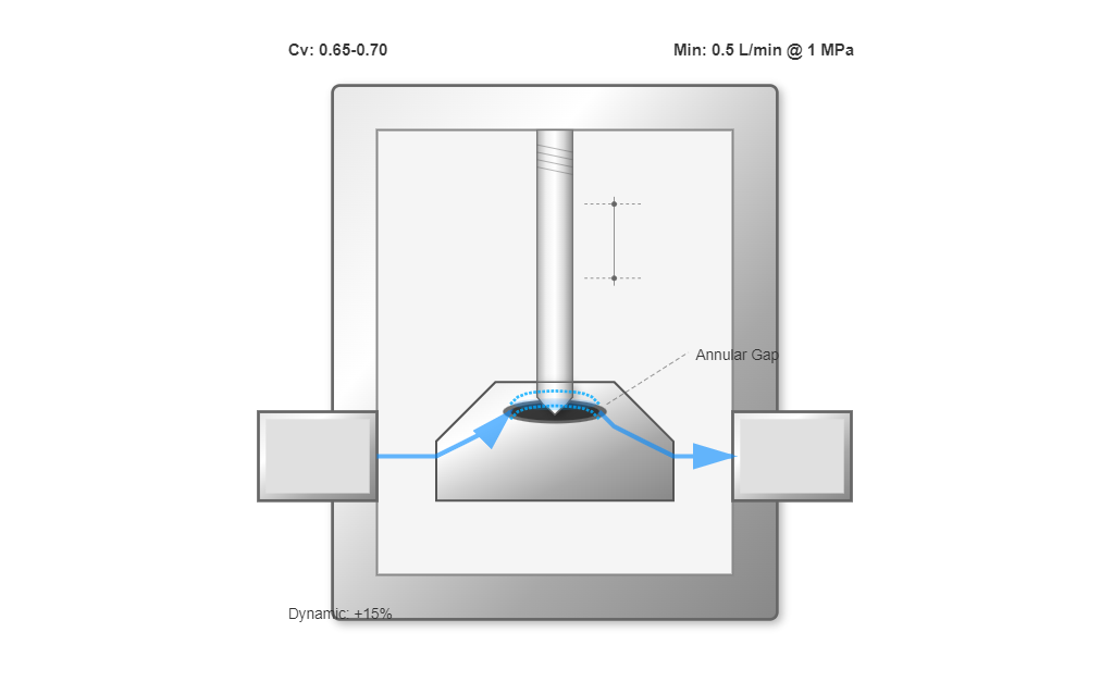
The needle valve represents the simplest throttling geometry, characterized by an annular flow gap between the valve stem and seat.
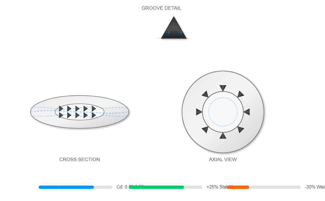
Triangular groove configurations, both circumferential and axial orientations, offer improved hydraulic radius characteristics.
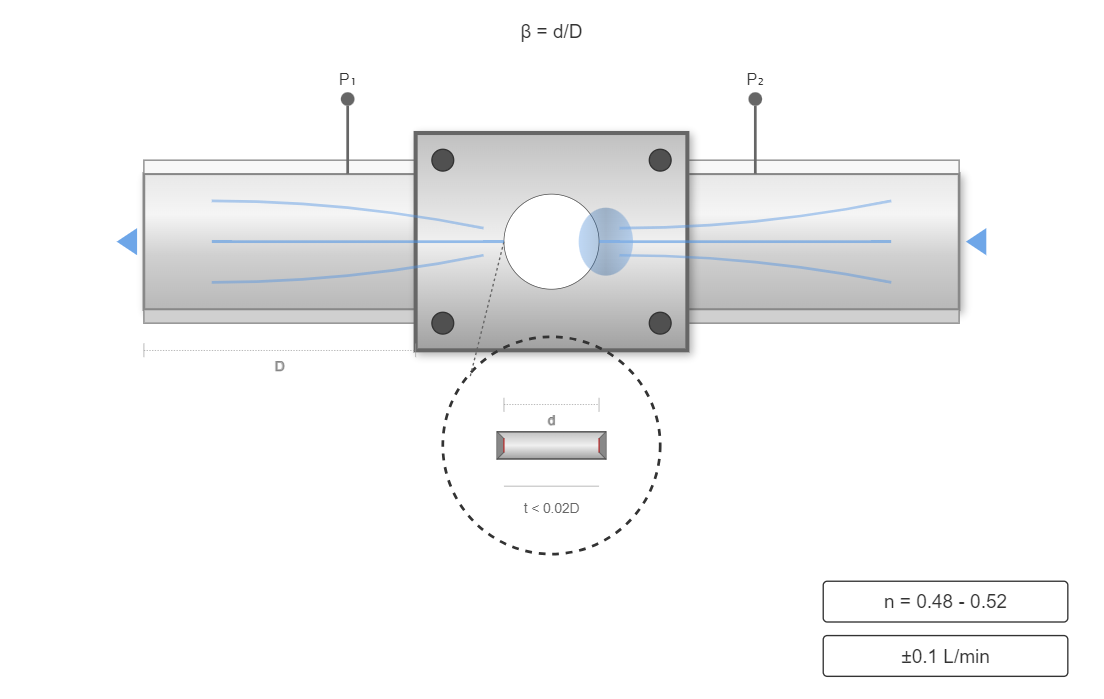
Advanced thin-walled orifice designs represent the pinnacle of flow control technology, approaching ideal sharp-edged orifice behavior.
Speed control valves integrate pressure-reducing mechanisms with throttling elements to maintain consistent flow rates despite load variations. Hydraulic flow meter measurements confirm that these valves maintain flow consistency within ±2% across pressure differential ranges of 1-20 MPa.
The incorporation of hydraulic flow meter feedback enables adaptive control strategies, further improving stability to ±0.8%.
"The integration of digital hydraulic flow meter technology with traditional speed control valves has demonstrated remarkable improvements in system efficiency."
Journal of Fluid Power Systems, Volume 45, Issue 3, 2024
Relief-throttle valves employ parallel flow paths to achieve pressure compensation. Hydraulic flow meter analysis reveals that these systems demonstrate superior efficiency characteristics, with energy losses 20% lower than series-compensated designs.
System efficiency calculations based on hydraulic flow meter measurements show that relief-throttle configurations achieve overall efficiencies of 82-87% in typical industrial applications.
The pressure compensation mechanism maintains a constant pressure differential of approximately 0.3 MPa across the throttling element, as verified by hydraulic flow meter readings. This consistency ensures that flow rates remain stable within ±3% despite load fluctuations of up to 80%. The hydraulic flow meter data indicates that optimal performance occurs at flow splits of 70% through the throttle path and 30% through the relief path under nominal conditions.
Comprehensive static performance characterization requires precise hydraulic flow meter instrumentation to quantify flow-pressure relationships. Laboratory testing using calibrated hydraulic flow meter systems reveals that modern flow control valves achieve linearity coefficients of 0.98-0.99 across their operational range.
| Valve Type | Minimum Stable Flow (L/min) | Minimum Pressure Differential (MPa) | Linearity Coefficient |
|---|---|---|---|
| Needle Valve | 0.5 | 0.8 | 0.95-0.97 |
| Triangular Groove | 0.2 | 0.6 | 0.97-0.98 |
| Thin-Walled Orifice | 0.05 | 0.5 | 0.98-0.99 |
| Speed Control | 0.1 | 1.0 | 0.98-0.99 |
The minimum stable flow rates, as measured by precision hydraulic flow meter equipment, range from 0.05-0.2 L/min depending on valve configuration.
Dynamic performance evaluation through hydraulic flow meter analysis reveals response times of 15-50 milliseconds for step input changes. High-frequency hydraulic flow meter sampling at 10 kHz captures transient phenomena, showing overshoot values of 5-12% for properly tuned systems.
The integration of hydraulic flow meter feedback with proportional control algorithms reduces settling times by 35% compared to open-loop configurations. Frequency response analysis using hydraulic flow meter data demonstrates that flow control valves exhibit bandwidth limitations of 20-50 Hz for mechanical designs and 100-200 Hz for servo-controlled variants.
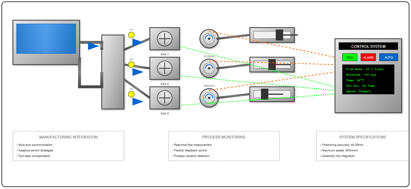
In manufacturing environments, hydraulic flow meter monitoring of flow control valves enables precise synchronization of multi-axis systems. Automotive assembly lines utilizing hydraulic flow meter feedback report positioning accuracies of ±0.05 mm at speeds up to 500 mm/s.
The hydraulic flow meter data facilitates adaptive control strategies that compensate for tool wear and process variations.
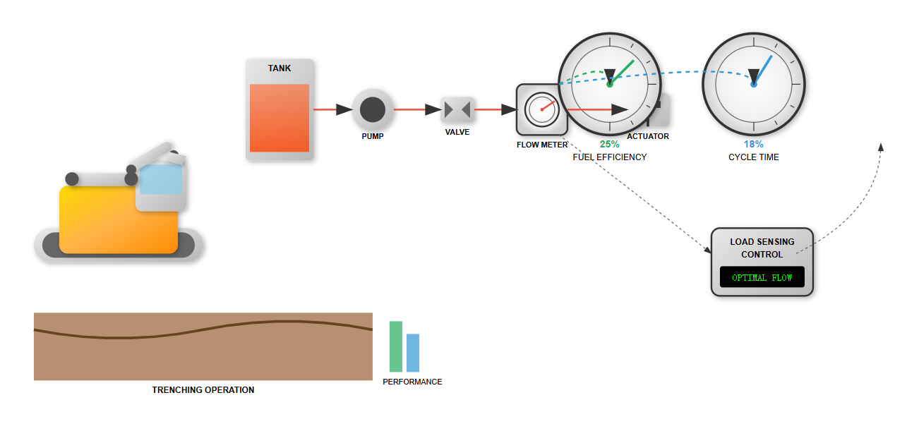
Construction and agricultural equipment increasingly rely on hydraulic flow meter technology for optimizing flow control valve performance. Excavator systems equipped with hydraulic flow meter monitoring demonstrate 25% improved fuel efficiency through load-sensing flow management.
The hydraulic flow meter data enables operators to maintain optimal flow rates across varying load conditions, reducing cycle times by 18% in typical trenching operations.
Injection molding applications benefit significantly from hydraulic flow meter integration, achieving shot-to-shot repeatability of ±0.5% in polymer flow rates. The hydraulic flow meter measurements enable real-time viscosity compensation, maintaining consistent product quality despite material batch variations of up to 15%.
Agricultural implements utilizing hydraulic flow meter feedback achieve seed placement accuracies of ±2% at speeds up to 15 km/h. The hydraulic flow meter integration enables automatic compensation for ground speed variations, maintaining consistent application rates despite terrain changes.
The implementation of hydraulic flow meter monitoring enables sophisticated predictive maintenance programs. Trend analysis of hydraulic flow meter data identifies degradation patterns 200-500 operational hours before functional failure.
Typical: 0.5-1% per 1000 hours
Acceptable: <5% per 2000 hours
Warning threshold: +10°C above baseline
Critical level: CI < 1.2
Statistical analysis of hydraulic flow meter data from 10,000 valve installations reveals mean time between failures (MTBF) of 15,000-25,000 hours for properly maintained systems.
Hydraulic flow meter measurements quantify the impact of fluid contamination on valve performance. Particles sized 25-40 microns cause flow variations of 2-5% as detected by hydraulic flow meter systems.
Implementation of hydraulic flow meter monitoring with contamination sensors enables proactive filter maintenance, maintaining ISO 4406 cleanliness levels of 18/16/13 or better. The correlation between contamination levels and valve wear rates, established through hydraulic flow meter studies, indicates that improving cleanliness from ISO 20/18/15 to 18/16/13 extends valve life by 250%.
Hydraulic flow meter data validates the economic benefits of enhanced filtration, showing return on investment periods of 8-12 months for upgraded filtration systems.
Hydraulic flow control valves regulate fluid velocity and volume, with modern systems achieving ±0.5% accuracy when integrated with flow meters.
The fundamental flow equation qT = KAT(ΔpT)m governs valve operation, with each parameter measurable by modern flow meters.
Different orifice configurations offer varying performance characteristics, with thin-walled designs providing the highest precision.
Pressure-compensated systems maintain consistent flow rates despite load variations, with relief-throttle designs offering 20% lower energy losses.
Flow meter monitoring reduces unplanned maintenance by 42% and enables predictive maintenance strategies that extend valve life.
Contamination control is critical, with improved filtration extending valve life by 250% and providing ROI within 8-12 months.