Search
Close this search box.

How to Better Use Hydraulic Cylinders?

Hydraulic cylinders are the actuators in hydraulic systems, responsible for converting hydraulic energy into mechanical energy. The input to a hydraulic cylinder consists of fluid flow and pressure, while the output is linear velocity and force. The piston of a hydraulic cylinder performs linear reciprocating motion, delivering a limited linear displacement.

1. Working Principle of Hydraulic Cylinders

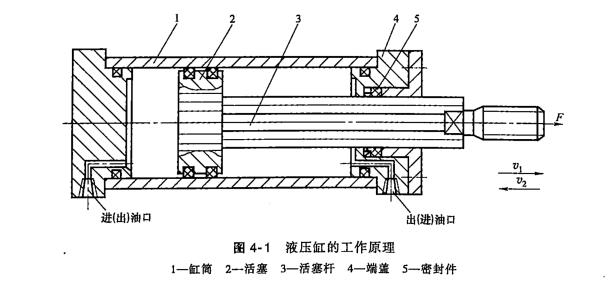
The working principle of a hydraulic cylinder is illustrated in Figure 4-1. A hydraulic cylinder consists of main components such as the cylinder barrel, piston, piston rod, end caps, and piston rod seals. Other types of piston hydraulic cylinders have similar main components to the structure shown in Figure 4-1.

If the cylinder barrel is fixed and hydraulic fluid is continuously fed into the left chamber, when the fluid pressure is sufficient to overcome all loads on the piston rod, the piston moves continuously to the right at velocity v, and the piston rod performs work on the external load. Conversely, when hydraulic fluid is fed into the right chamber, the piston moves to the left at velocity v, and the piston rod again performs work externally. This completes one reciprocating cycle. Such a hydraulic cylinder is called a fixed-cylinder type. If the piston rod is fixed and hydraulic fluid is continuously fed into the left chamber, the cylinder barrel moves to the left; when fluid is fed into the right chamber, the cylinder barrel moves to the right. This is called a fixed-piston-rod type. Unless otherwise specified, the hydraulic cylinders discussed in this chapter are of the fixed-cylinder, moving-piston-rod type.

Thus, the fluid entering the hydraulic cylinder must have pressure p and flow rate q. The pressure overcomes the load, while the flow rate determines the motion speed. The pressure and flow rate input to the cylinder represent the hydraulic energy, while the force and velocity of the piston acting on the load represent the mechanical energy output. Therefore, the input pressure p, flow rate q, output force F, and velocity v are the main performance parameters of a hydraulic cylinder.

2. Classification of Hydraulic Cylinders

To meet the diverse needs of various applications, hydraulic cylinders are available in multiple types:

  1. By Oil Supply Direction:
    Hydraulic cylinders are classified into single-acting and double-acting cylinders. Single-acting cylinders supply high-pressure oil to only one side of the cylinder, with the piston returning via external forces. Double-acting cylinders supply hydraulic fluid to both sides, with piston movement in both directions driven by hydraulic pressure.
  2. By Structural Form:
    Hydraulic cylinders can be categorized as piston cylinders, plunger cylinders, swing cylinders, and telescopic sleeve cylinders.
  3. By Piston Rod Form:
    Hydraulic cylinders are divided into single-piston-rod and double-piston-rod cylinders.
  4. By Special Applications:
    Hydraulic cylinders include series cylinders, booster cylinders, speed-increasing cylinders, and stepping cylinders. These are not standalone cylinder barrels but are combined with other cylinders or components, making them composite cylinders from a structural perspective. The classification of cylinders is shown in Table 4-1.

3.Typical Structure of Hydraulic Cylinders

Example of a Typical Hydraulic Cylinder Structure

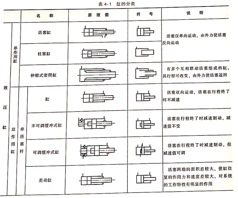
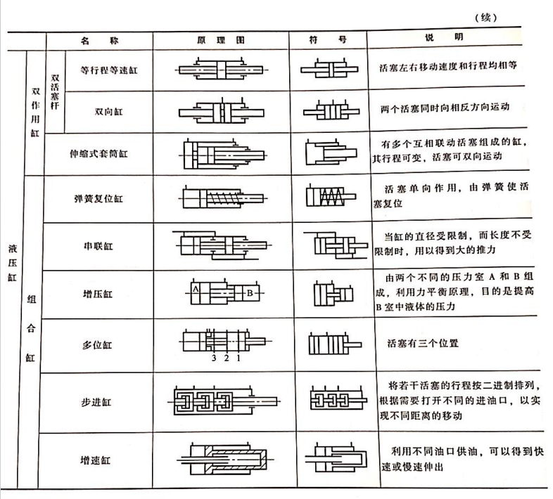
Figure 4-13 illustrates the structure of a double-acting single-rod piston hydraulic cylinder, commonly used in construction machinery. Its main components include the cylinder base (2), piston (8), cylinder barrel (11), piston rod (12), guide sleeve (13), and end cap (15). The structural features of this cylinder include:

  • The piston and piston rod are connected with a snap ring, facilitating easy assembly and disassembly.
  • The support ring (9) on the piston is made of wear-resistant materials like PTFE, reducing friction.
  • The guide sleeve ensures the piston rod moves axially without tilting, protecting the seals.
  • Both ends of the cylinder are equipped with slit-type buffering devices to reduce impact and noise when the piston reaches the end of its stroke. This type of cylinder operates at a working pressure of 12–15 MPa.

The following sections describe the common structures of the main components of this hydraulic cylinder.

Components of a Hydraulic Cylinder

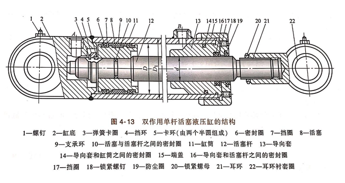
From Figure 4-13, the structure of a hydraulic cylinder can be divided into five main parts: cylinder barrel and end cap, piston and piston rod, sealing devices, buffering devices, and exhaust devices.

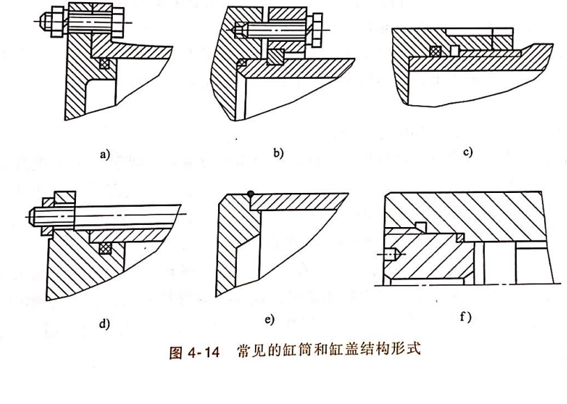
1.Cylinder Barrel and End Cap
The structure of the cylinder barrel and end cap depends on the materials used. For working pressures p < 10 MPa, cast iron is used; for p < 20 MPa, seamless steel tubes are used; and for p > 20 MPa, steel or forged steel is used.

Common cylinder barrel and end cap structures are shown in Figure 4-14:

    • Figure 4-14a: Flange connection structure. This structure is simple, easy to manufacture and assemble, but has larger dimensions and weight, commonly used for cast iron cylinder barrels.
    • Figure 4-14b: Half-ring connection structure. This includes outer and inner half-ring connections. The cylinder wall is weakened by an annular groove, sometimes requiring a thicker wall. It is easy to process and assemble, with lower weight, and is widely used for seamless steel or forged steel cylinders.
    • Figure 4-14c, f: Threaded connection structure. This includes external and internal threading. The cylinder end structure is complex, requiring concentricity between inner and outer diameters during machining, and special tools for assembly and disassembly. It has compact dimensions and lower weight, commonly used for seamless steel or forged steel cylinders.
    • Figure 4-14d: Tie-rod connection structure. This structure is simple, highly manufacturable, versatile, and easy to assemble and disassemble. However, the end cap is bulky and heavy, and the tie rods may stretch under load, affecting sealing performance, so it is only used for short, low-to-medium-pressure cylinders.
    • Figure 4-14e: Welded connection structure. This connection is strong and simple to manufacture but may cause cylinder deformation during welding.

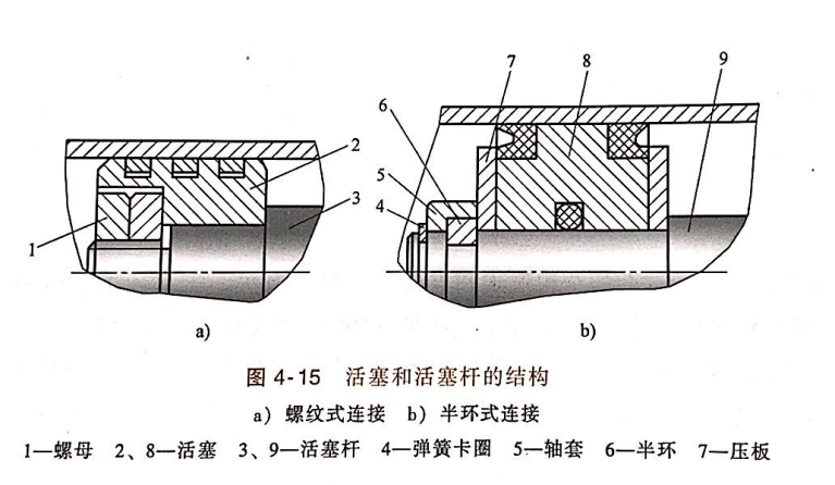
2.Piston and Piston Rod
Piston and piston rod structures vary, including integral, taper pin, threaded, and half-ring connections, as shown in Figure 4-15.
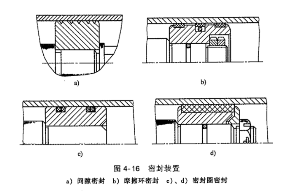
    • Threaded connections are simple and easy to assemble but require anti-loosening devices under high pressure and load.
    • Half-ring connections are complex and less convenient to assemble but reliable in operation.
    • Integral structures are used for smaller-sized applications.
      Pistons are typically made of wear-resistant cast iron, while piston rods, whether hollow or solid, are generally made of steel.

3.Sealing Devices
Common sealing devices in hydraulic cylinders are shown in Figure 4-16:

  • Figure 4-16a: Gap sealing relies on a small gap between moving parts to prevent leakage. To enhance sealing, small annular grooves are often made on the piston surface to increase resistance to fluid leakage. This structure is simple, has low friction, and can withstand high temperatures, but it has higher leakage, high machining requirements, and cannot restore its original capability after wear. It is used for small-sized, low-pressure, high-speed cylinders.
  • Figure 4-16b: Friction ring sealing uses a friction ring (made of nylon or other polymers) on the piston, pressed against the cylinder wall by an O-ring’s elasticity to prevent leakage. This structure offers good sealing, stable low friction, high-temperature resistance, and automatic wear compensation, but it requires high machining precision and is less convenient to assemble. It is suitable for sealing between the cylinder barrel and piston.
  • Figure 4-16c, d: Sealing ring (O-ring, V-ring, etc.) sealing uses the elasticity of rubber or plastic rings to seal interference or clearance fits. This structure is simple, easy to manufacture, automatically compensates for wear, and is reliable, making it suitable for sealing between the cylinder barrel and piston, piston and piston rod, or cylinder barrel and end cap.