
A comprehensive technical overview of one of the most fundamental components in fluid power systems, exploring design principles, operational characteristics, and advanced control strategies.
The hydraulic control valve represents one of the most fundamental components in fluid power systems, serving as the critical interface between control signals and hydraulic actuators. In modern industrial applications, the hydraulic control valve enables precise manipulation of fluid flow direction, pressure, and volume, making it indispensable for machinery ranging from construction equipment to precision manufacturing systems.
The evolution of hydraulic control valve technology has paralleled advances in industrial automation, with current designs achieving switching frequencies exceeding 100 Hz and flow capacities ranging from 10 to 5000 liters per minute.
The hydraulic control valve family encompasses multiple configurations, each optimized for specific operational requirements. The most prevalent classification divides these devices into two-position, three-position, and four-position variants, with port configurations ranging from two-way to six-way designs.
Statistical analysis of industrial applications reveals that three-position, four-way valves constitute approximately 65% of all hydraulic control valve installations in mobile equipment, while two-position variants dominate stationary industrial systems at 58% market share.
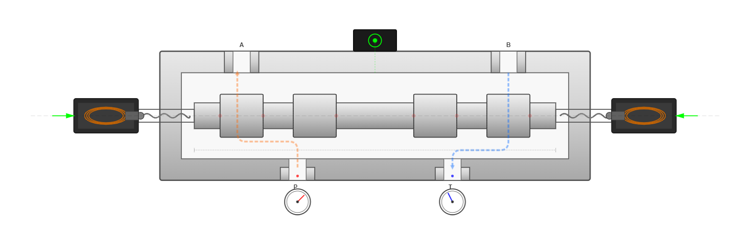
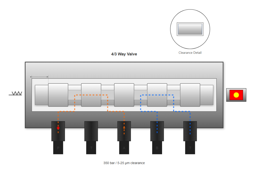
The operating principle of a sliding spool hydraulic control valve involves precise mechanical displacement of a cylindrical spool within a closely toleranced bore. Manufacturing tolerances typically maintain clearances between 5-25 micrometers, ensuring minimal internal leakage while permitting smooth operation.
The spool features strategically positioned lands and grooves that alternately connect and isolate fluid passages as the spool translates axially. Modern hydraulic control valve designs achieve leakage rates below 5 cm³/min at operating pressures of 350 bar, representing a 40% improvement over designs from the previous decade.
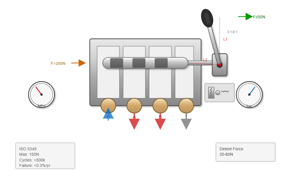
Manual hydraulic control valve systems remain prevalent in applications requiring direct operator control and enhanced reliability. These systems typically employ lever mechanisms with mechanical advantage ratios ranging from 3:1 to 8:1, enabling operators to overcome flow forces exceeding 200 N with applied forces below 50 N.
The integration of detent mechanisms ensures positive positioning, with steel ball detent systems providing retention forces between 20-80 N depending on spring preload settings.
Contemporary manual hydraulic control valve designs incorporate ergonomic considerations, limiting operating forces to 150 N maximum per ISO 5349 standards for sustained operation. Field studies demonstrate that manual systems maintain operational reliability exceeding 500,000 cycles when properly maintained, with failure rates below 0.3% annually in construction equipment applications.
Mechanically actuated directional valves, commonly termed cam-operated or stroke valves, utilize physical contact with machine components to initiate switching. The hydraulic control valve in this configuration typically incorporates roller followers with diameters ranging from 12-50 mm, designed to withstand contact forces up to 500 N.
Spring return mechanisms employ compression springs with rates between 5-50 N/mm, ensuring positive return to neutral position within 50-200 milliseconds of cam disengagement.
Industrial implementation data indicates that mechanical hydraulic control valve systems achieve positioning accuracy within ±0.5 mm over 1,000,000 operational cycles.
The primary advantage lies in their inherent synchronization with machine motion, eliminating the need for separate position sensing systems. However, installation constraints limit their application to situations where actuator travel permits direct mechanical interface with the hydraulic control valve assembly.
Solenoid-operated hydraulic control valve technology represents the predominant control method in automated systems, accounting for approximately 70% of new installations. Direct-acting solenoid valves typically operate with flow rates up to 60 L/min at pressure differentials of 350 bar, limited by available electromagnetic force generation.
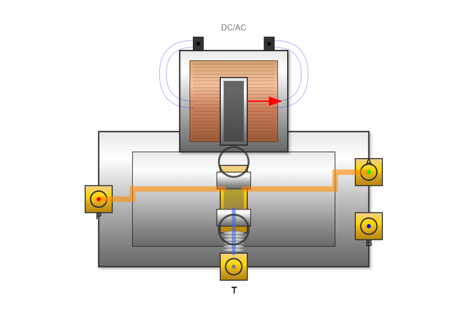
"Modern wet-armature solenoid designs for hydraulic control valve applications achieve response times below 15 milliseconds while maintaining contamination tolerance to ISO 4406 18/16/13 fluid cleanliness levels. The elimination of dynamic seals between the solenoid and valve sections reduces friction by 60% compared to dry-armature configurations, enabling operation at pressure differentials exceeding 420 bar"
Source: International Fluid Power Society Technical Bulletin 2024, www.ifps.org
Temperature considerations significantly impact solenoid hydraulic control valve performance. Coil resistance increases approximately 0.4% per degree Celsius for copper windings, reducing force output proportionally. Thermal management strategies include integration of heat sinks achieving thermal resistance below 2°C/W and utilization of high-temperature insulation systems rated for 180°C continuous operation. Advanced hydraulic control valve designs incorporate temperature compensation circuits maintaining force output variation within ±5% across -40°C to +80°C operating ranges.
Hydraulically piloted directional valves overcome flow force limitations inherent in direct solenoid actuation. The pilot hydraulic control valve typically operates with flow rates of 2-10 L/min at pressures of 10-50 bar, generating control forces up to 5000 N on main stage spools. This amplification enables main stage flow capacities exceeding 2000 L/min at operating pressures to 420 bar.
Vary with pilot flow rate and main spool mass, typically achieving full stroke in 30-150 milliseconds.
Pilot pressure constitutes 3-10% of system pressure, with minimum levels of 10-15 bar ensuring reliable operation.
Statistical analysis demonstrates MTBF exceeding 15 million cycles for properly maintained pilot systems.
The hydraulic control valve pilot circuit incorporates filtration to 10-micron absolute, protecting precision pilot components from contamination-induced malfunction. Statistical reliability analysis demonstrates MTBF exceeding 15 million cycles for properly maintained pilot systems, substantially exceeding direct-acting alternatives in high-flow applications.
Electrohydraulic hydraulic control valve systems combine the controllability of electrical signals with the force amplification of hydraulic pilots. These sophisticated devices integrate pilot solenoid valves rated at 1-5 L/min with main stages handling 100-1000 L/min flows.
The pilot section typically employs proportional solenoids providing infinitely variable positioning within ±0.1% of stroke length, enabling precise flow modulation in the main hydraulic control valve stage.
Performance metrics for electrohydraulic systems include step response times of 25-80 milliseconds for 0-100% stroke transitions and frequency response extending to 100 Hz at -3dB amplitude. Hysteresis remains below 3% of full scale with modern magnetic materials and optimized magnetic circuit designs.
The main stage hydraulic control valve incorporates position feedback via LVDT sensors providing resolution to 0.01 mm, enabling closed-loop position control with steady-state errors below 0.5% of commanded position.
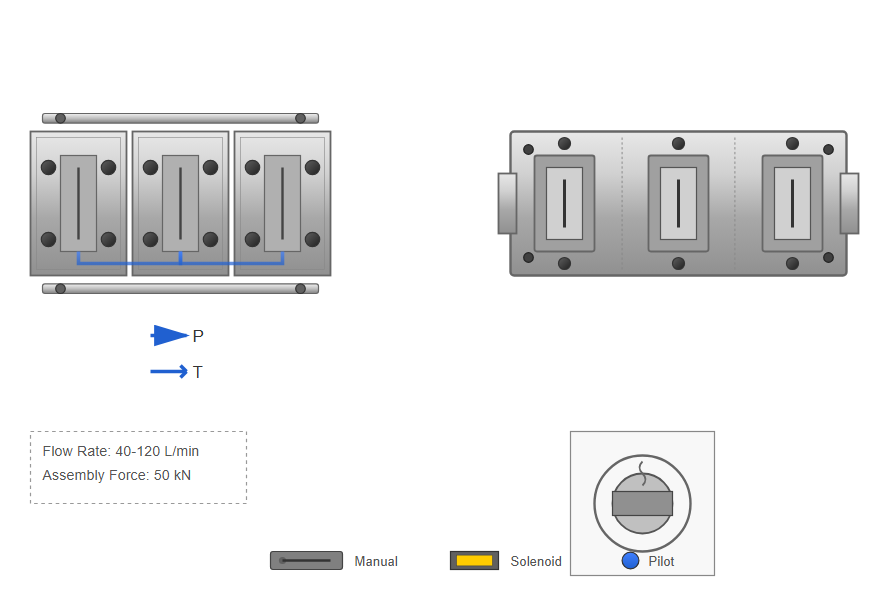
Multi-station hydraulic control valve assemblies, commonly termed stack valves or mobile valves, integrate multiple directional control functions within compact packages. Sectional designs utilize individual valve sections rated for 40-120 L/min per section, mechanically coupled via tie rods capable of withstanding assembly forces to 50 kN.
| Characteristic | Sectional Design | Monobloc Design |
|---|---|---|
| Configuration | Individual sections coupled with tie rods | Multiple stations in single casting |
| Weight | Heavier | 25-35% lighter |
| Pressure Loss | Higher | 30-40% lower |
| Flexibility | High - easy reconfiguration | Limited - fixed configuration |
| Pressure Rating | Up to 420 bar | 250-420 bar depending on material |
| Typical Applications | Industrial systems, complex circuits | Mobile equipment, space-constrained applications |
This modular approach enables configuration flexibility, with systems incorporating 2-12 sections depending on application requirements. Monobloc hydraulic control valve designs cast multiple valve stations within single housings, achieving weight reductions of 25-35% compared to equivalent sectional assemblies. Manufacturing processes employ high-pressure die casting for aluminum bodies rated to 250 bar or sand casting for ductile iron versions handling pressures to 420 bar. Internal passage optimization through computational fluid dynamics reduces pressure losses by 30-40% compared to sectional designs, improving overall system efficiency.
Contemporary mobile hydraulic control valve systems incorporate sophisticated load sensing capabilities, maintaining constant pressure margins of 15-30 bar above load requirements. This technology reduces power consumption by 20-35% compared to fixed displacement systems while providing consistent actuator response independent of load variations.
The load sense hydraulic control valve network communicates the highest load pressure to the pump controller via dedicated signal lines maintaining pressure drop below 2 bar at maximum flow conditions.
Flow sharing hydraulic control valve configurations enable simultaneous operation of multiple functions with predetermined flow distribution ratios. Priority flow dividers integrated within the valve assembly allocate available flow based on operator input, with primary functions receiving 60-80% of available flow and secondary functions utilizing excess capacity.
This technology proves essential in mobile equipment where engine power limitations restrict total hydraulic power to 50-200 kW.
Combined, load sensing and flow sharing technologies represent the most significant efficiency advancements in hydraulic control valve design over the past three decades. Field data from construction equipment retrofits demonstrates fuel savings of 15-25% while maintaining or improving machine productivity. These systems also reduce heat generation by 30-40%, extending fluid life and reducing cooling system requirements.
Industrial hydraulic control valve specifications encompass broad operational ranges to accommodate diverse applications. Nominal flow ratings span from 10 L/min for compact industrial valves to 5000 L/min for large mobile equipment valves.
The relationship between flow rate and pressure drop follows quadratic characteristics, with pressure losses proportional to flow rate squared. Typical hydraulic control valve designs maintain pressure drops below 5 bar at rated flow, though high-performance racing applications accept losses to 15 bar for enhanced response characteristics.
Maximum operating pressures for standard hydraulic control valve products range from 210 bar for aluminum body mobile valves to 420 bar for steel industrial variants. Specialized high-pressure designs achieve ratings to 700 bar through optimized seal configurations and reduced clearances. Proof pressure testing at 1.5 times rated pressure ensures structural integrity, while burst pressure ratings typically exceed 4 times nominal pressure per ISO 4411 requirements.
The dynamic performance of a hydraulic control valve significantly impacts system controllability and productivity. Response time measurement from neutral to fully shifted position ranges from 15 milliseconds for small direct-acting solenoid valves to 200 milliseconds for large pilot-operated designs.
These specifications assume step input signals and exclude hydraulic delays associated with fluid compression and line dynamics.
Frequency response testing reveals -3dB bandwidth ranging from 25 Hz for large hydraulic control valve assemblies to 150 Hz for servo-quality proportional valves. Phase lag at 10 Hz typically measures 15-45 degrees, increasing to 90-180 degrees at the -3dB frequency.
These characteristics determine suitability for closed-loop control applications where phase margin requirements necessitate adequate bandwidth margins.
Internal leakage represents a critical hydraulic control valve performance parameter affecting both efficiency and controllability. Manufacturing tolerances maintain radial clearances of 5-25 micrometers between spool and bore, resulting in leakage flows of 50-500 cm³/min at 100 bar differential pressure for nominal size 10 valves.
Temperature effects alter viscosity, causing leakage variation of ±50% across typical operating ranges. This significant variation necessitates careful consideration in system design, particularly for applications with wide temperature fluctuations.
Volumetric efficiency for new valves typically ranges from 96-98%, degrading to 92-95% after extended service due to wear and contamination effects.
Volumetric efficiency calculations for hydraulic control valve systems must account for both internal leakage and compressibility effects. At 200 bar operating pressure, mineral oil compressibility of 0.7% per 100 bar reduces effective flow by 1.4%, while internal leakage subtracts an additional 0.5-2% depending on valve condition. Combined losses limit volumetric efficiency to 96-98% for new valves, degrading to 92-95% after extended service.
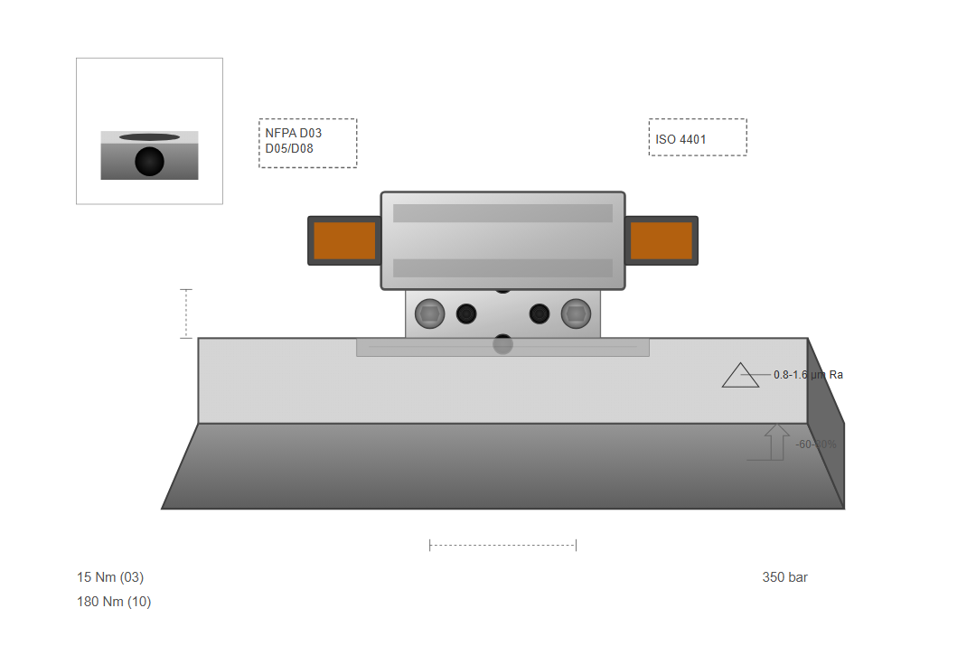
Standardized mounting patterns ensure hydraulic control valve interchangeability across manufacturers. ISO 4401 and NFPA D03/D05/D08 patterns dominate industrial applications, with bolt patterns and port locations precisely defined for each frame size.
Contamination control proves critical for hydraulic control valve longevity and performance maintenance. Recommended filtration levels range from ISO 4406 20/18/15 for general industrial applications to 16/14/11 for servo-quality proportional valves.
Particle ingression studies demonstrate that contamination-related failures account for 70-80% of hydraulic control valve malfunctions, emphasizing filtration importance.
Beta ratio specifications for hydraulic control valve protection typically require β₁₀ ≥ 75 for pressure filters and β₂₅ ≥ 200 for return filtration. Filter placement upstream of sensitive hydraulic control valve components reduces silt-lock probability by 90% compared to unfiltered systems. Magnetic filtration supplementing mechanical media removes ferrous particles below 5 micrometers, extending valve life by 25-40% in high-contamination environments.
Modern maintenance approaches for hydraulic control valve systems emphasize condition monitoring over time-based replacement. Vibration analysis detects cavitation and mechanical wear, with acceleration levels exceeding 10 g indicating imminent failure.
Identifies internal leakage through temperature rise, with differentials exceeding 10°C suggesting excessive clearances.
Response degradation exceeding 20% from baseline indicates contamination buildup or seal deterioration.
Identifies internal leakage paths, enabling targeted maintenance before catastrophic failure.
Extends service intervals by 40-60% while reducing unexpected failures by 75%.
Contemporary hydraulic control valve systems increasingly incorporate digital control interfaces enabling sophisticated control algorithms and remote monitoring capabilities. Fieldbus protocols including CANopen, PROFIBUS, and EtherCAT provide communication speeds to 100 Mbit/s, enabling real-time control with update rates exceeding 1 kHz.
Digital hydraulic control valve controllers integrate PID algorithms with adaptive gains, maintaining position accuracy within ±0.1% despite load and temperature variations.
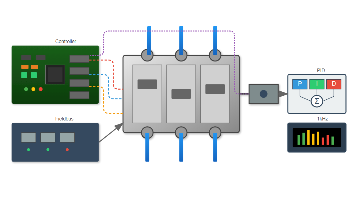
On-board diagnostics monitor critical hydraulic control valve parameters including coil current, spool position, and temperature. Fault detection algorithms identify developing problems before performance degradation affects production. Data logging capabilities record operational history, facilitating root cause analysis and warranty validation. Integration with Industrial Internet of Things (IIoT) platforms enables cloud-based analytics and predictive maintenance scheduling.
Energy conservation drives continuous hydraulic control valve development focusing on reduced pressure losses and improved control strategies. Variable margin pressure control maintains minimum pressure differentials of 7-10 bar above load requirements, reducing power consumption by 30-40% compared to fixed pressure systems.
Independent metering hydraulic control valve technology separately controls meter-in and meter-out functions, enabling energy recovery during overrunning loads. This approach can improve system efficiency by an additional 15-20% in appropriate applications.
Digital displacement technology represents an emerging hydraulic control valve control strategy achieving efficiencies exceeding 95% across broad operating ranges. Individual cylinder control via high-speed valves rated for 100 Hz operation enables displacement variation without throttling losses. Early implementations demonstrate fuel savings of 20-30% in mobile equipment applications while maintaining response characteristics comparable to conventional systems.
Hydraulic control valve technology continues to evolve in response to demands for increased efficiency, precision, and reliability across industrial and mobile applications. From basic manual valves to sophisticated electrohydraulic systems with digital connectivity, these components remain essential elements in modern fluid power systems.
The ongoing development of energy-efficient designs, enhanced contamination resistance, and advanced control integration ensures that hydraulic control valve technology will continue to play a vital role in industrial automation for decades to come.