
We work with fleet managers and equipment engineers who come to us after standard cylinders have already caused problems. Last month, a mining contractor called about boom cylinders that were overheating on every shift. The cylinders looked fine on paper—right tonnage rating, right pressure spec. But the bore was 0.3 inches too small. That tiny difference meant his pumps ran at relief pressure 40% of every cycle, cooking the oil and burning an extra 200 gallons of diesel per machine every month.
That’s what happens when bore size gets treated like a checkbox instead of an engineering decision. You don’t just lose efficiency. You lose money, uptime, and eventually the entire cylinder when seals fail from excessive heat.
I’m writing this because procurement teams keep getting handed generic catalogs when they need actual calculations. Your application isn’t generic. A 20-ton excavator loading trucks in a quarry has completely different requirements than the same machine doing precision grading work. The bore size that works for one will absolutely wreck performance in the other.
So let’s walk through how this actually works—not the textbook version, but the version that keeps cylinders running in dirt, heat, and 12-hour shifts.
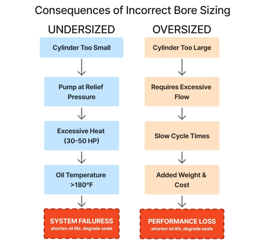
Before we touch any equations, you need to understand what breaks when the bore doesn’t match the work.
Undersized bores force your pump to operate at maximum relief pressure just to move the load. Picture your relief valve cracking open multiple times per minute, converting 30-50 horsepower directly into heat. That’s not inefficiency—that’s burning fuel to accomplish nothing. Your oil temperature climbs. Seals age faster. Hoses degrade. And your operator notices the sluggish response, so they start hammering controls harder, which compounds the problem.
Oversized bores seem safer, right? More capacity equals better performance? Except now you’ve got a cylinder that needs 35 gallons per minute when your pump only delivers 28 GPM. Cycle times stretch out. Operators get frustrated. Productivity drops. And because you’re using a cylinder that’s physically larger and heavier than necessary, you’ve also added weight to the boom structure, which reduces your payload capacity.
A customer in Texas—running a fleet of excavators in pipeline work—was seeing boom cylinder failures every 1,800 hours. The OEM replacement spec called for 4.75-inch bores. We calculated their actual load requirements and found they needed 5.1 inches. The larger bore dropped operating pressure by 180 PSI during typical digging cycles. Those cylinders are now past 4,000 hours with zero failures. The difference in upfront cost? About $340 per cylinder. The difference in downtime and replacement costs? Over $8,000 per machine per year.
That’s why we’re having this conversation. Bore size isn’t about picking a dimension that’s “close enough.” It’s about matching the cylinder’s force output to your actual work so the entire excavator hydraulic system runs in its efficient zone instead of fighting itself.
The physics is actually simple. Force equals pressure times area. That’s it. But the way these three variables interact creates all the complexity in cylinder selection.
Pressure comes from your pump and relief valve—typically 3,200 to 3,800 PSI on modern excavators. You don’t usually change this. It’s set by your system design.
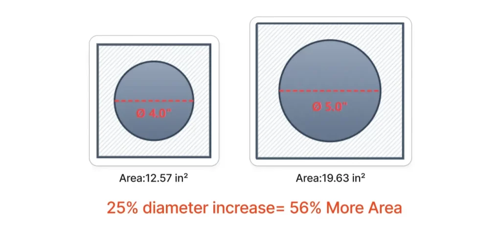
Area is what you control with bore size. A 4-inch bore gives you 12.57 square inches of piston area. A 5-inch bore gives you 19.63 square inches—56% more area from a 25% increase in diameter. That’s because area grows with the square of the diameter. Small bore changes create big force differences.
Force is what comes out the other end—the actual pushing or pulling power the cylinder delivers. At 3,500 PSI, that 4-inch cylinder generates 44,000 pounds of force. The 5-inch cylinder generates 68,700 pounds. Same pressure, different area, massive difference in output.
Now here’s where it gets interesting for custom hydraulic cylinder design. That force number assumes the piston is actually seeing full system pressure. In reality, pressure drops occur across valves, hoses, and fittings. By the time oil reaches the cylinder, you might only have 3,300 PSI available. That 5-inch cylinder you thought would generate 68,700 pounds? It’s actually making 64,800 pounds. Still strong, but 6% less than your calculation suggested.
This is why we start every cylinder specification by measuring the actual pressure at the cylinder ports under load, not just looking at the relief valve setting. Real-world pressure tells you what bore you actually need, not what the theory suggests.
Bigger bores generate more force. Everyone knows that. What gets ignored is how much more oil volume you need to move that piston.
Look at these numbers for a 40-inch stroke:
4.0″ bore:
5.0″ bore:
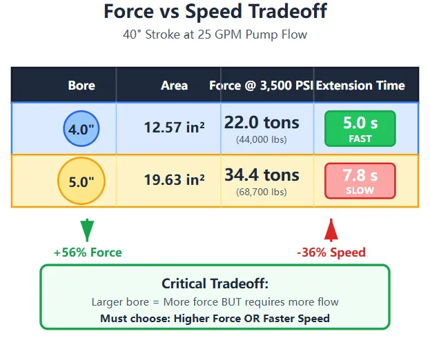
You gained 56% more force but lost 56% of your speed. The pump doesn’t care about your force requirement. It delivers a fixed flow rate. More area means more volume, which means slower movement unless you upgrade the pump.
I’ve watched engineers calculate the perfect bore for force, then get blindsided when the prototype extends too slowly for production work. Operators reject equipment that feels sluggish, even if it’s technically capable. Speed matters as much as force, which means bore size selection requires balancing both variables against your pump capacity.
One approach we use regularly: regenerative circuits. Route the return oil from the rod side back into the cap side during extension. You’re effectively adding flow without upgrading the pump. It only works in one direction, but for boom or arm cylinders where extension speed matters more than retraction speed, it solves the problem without requiring a larger pump or smaller bore.
Boom cylinders lift the entire arm assembly plus whatever you’ve loaded into the bucket. That’s a straightforward static load calculation—add up the weights, multiply by a safety factor, divide by the number of cylinders. Except that’s not how boom cylinders actually work.
The load changes throughout the stroke. When the boom is fully lowered and you start lifting, the cylinder operates at a significant mechanical advantage—maybe 4:1 or 5:1 depending on linkage geometry. The cylinder might only need to generate 6,000 pounds to lift 24,000 pounds of arm and bucket.
But as the boom rises and approaches horizontal, that mechanical advantage drops. At some point mid-stroke, the geometry shifts and the cylinder is working almost 1:1 against the load. Now you need 24,000 pounds of cylinder force to support that same 24,000-pound load. Keep raising the boom past horizontal, and you get mechanical advantage working in your favor again, but in the opposite direction—gravity is now helping lower the boom rather than resisting the lift.
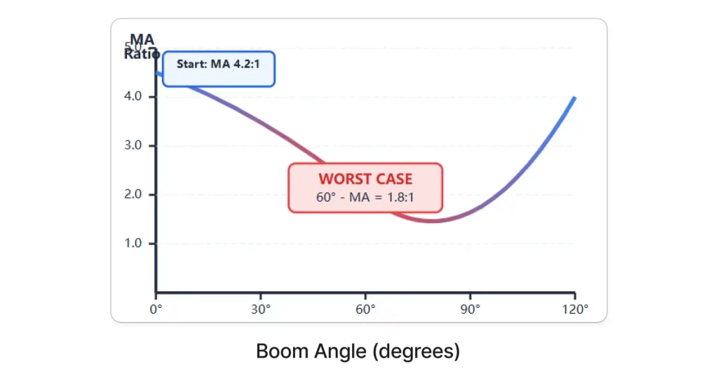
This means your “required force” isn’t a single number. It’s a curve that peaks somewhere mid-stroke. We’ve measured boom cylinders that need 35% more force at 60-degree boom angle than they need at full down or full up positions.
Excavator hydraulic cylinder sizing has to account for this worst-case angle. Otherwise, you design for the average load and discover the cylinder stalls halfway through the lifting cycle when geometry works against you.
Let’s work through an actual example instead of speaking abstractly.
Say you’ve got a 20-ton excavator. The boom, arm, and bucket together weigh 8,500 pounds. Maximum bucket payload is 4,800 pounds. Total suspended weight: 13,300 pounds.
Your boom linkage provides 4.2:1 mechanical advantage at the bottom of the stroke but drops to 1.8:1 at the worst-case angle. You’ve got two boom cylinders sharing the load equally.
At the worst-case angle, each cylinder needs to support:
At 3,500 PSI system pressure, you need:
That corresponds to about a 1.3-inch bore, which sounds impossibly small. And it is—because we haven’t accounted for cylinder angularity. The cylinder doesn’t push straight vertical. It operates at an angle to the direction you want the boom to move. That angle reduces effective force by the cosine of the angle.
If your cylinder is mounted at 25 degrees off vertical during the worst-case load condition:
Now we’re getting somewhere realistic. But you still wouldn’t specify a 1.4-inch bore. Why? Because that calculation assumes everything is perfect—no pressure drops, no seal friction, no wear, no contamination. Real cylinders operating in dirt and heat with 2,000 hours on the seals don’t deliver theoretical force.
Experienced engineers add 10-15% margin for these real-world losses. That brings your required bore to 4.6-4.8 inches. And in practice, you’d probably round up to 5.0 inches because standard rod diameters and seal kits are more readily available in round numbers.
This is what proper boom cylinder specifications look like when you account for linkage geometry, mounting angles, and real-world operating conditions instead of just dividing load by pressure.
Arm cylinders work differently than boom cylinders. They’re not fighting gravity as much as they’re fighting material resistance. When you crowd the arm into a pile of compacted fill or fractured rock, the cylinder needs to generate enough force to drive the bucket through that material.
This is called breakout force, and it’s where undersized cylinders become obvious. An operator loads the bucket, starts to curl it, and feels the cylinder stall. They pull back, try again with more throttle, maybe impact the pile instead of smoothly penetrating it. All of that is the machine compensating for a cylinder that can’t generate adequate force at the bucket teeth.
The tricky part is that breakout force doesn’t equal cylinder force. You’ve got linkage geometry converting cylinder extension into bucket curl motion, and that geometry changes throughout the stroke.
We worked with a contractor who was consistently breaking bucket linkage pins on a fleet of 30-ton excavators. The OEM arm cylinders were 5.5-inch bore, which should have been plenty. Except when we measured actual breakout force during typical digging cycles, we found the cylinders were generating peak force at the wrong point in the stroke. The linkage geometry provided maximum mechanical advantage when the bucket was nearly full-curl, but the operator needed maximum force during initial penetration when the bucket was extended.
The fix wasn’t a larger bore. It was a custom stroke length and different mounting positions that shifted the force curve earlier in the bucket cycle. Same bore, different geometry, completely different performance. That’s why we push back when customers ask us to “just make it bigger.” Bigger isn’t always the answer if the geometry is wrong.
For arm cylinders, start with your target breakout force at the bucket teeth. Let’s say you need 32,000 pounds of curl force. Your linkage might provide 5:1 mechanical advantage during the working part of the stroke, meaning your cylinder needs to generate 6,400 pounds.
But that 5:1 advantage only exists during part of the motion. At full extension when you’re trying to penetrate hard material, the geometry might only give you 3.5:1. Now you need 9,150 pounds from the cylinder.
Add your safety factor: 9,150 × 1.25 = 11,440 pounds required cylinder force.
At 3,600 PSI (arm circuits often run slightly higher pressure than boom circuits):
Same issue as before—that’s the theoretical minimum. Real-world losses and the desire for force margin pushes you toward 4.5 to 4.75-inch bores for this application.
The other consideration for arm cylinders is extension speed. Operators want fast positioning. A larger bore slows extension unless you increase pump flow or implement regenerative circuits. We’ve built arm cylinders where the customer specifically chose a slightly smaller bore than force calculations suggested because they prioritized cycle time over having force margin they’d rarely use.
Bucket cylinders face the tightest space constraints. They need to fit within the arm-to-bucket linkage geometry, which usually means shorter stroke and more compact mounting than boom or arm cylinders. Despite the packaging challenges, they need to generate substantial force to achieve high breakout performance at the bucket teeth.
The complicating factor is the cylinder operates at severe angles during peak loading. When you’re curling a loaded bucket, the cylinder might be pushing at 35-40 degrees off the ideal force direction. That angular offset kills your effective force.
Here’s what that looks like mathematically:
If your cylinder generates 24,000 pounds of force but operates at 38 degrees off the direction you want the bucket to move:
You lost 21% of your force to geometry. To deliver 24,000 pounds of effective curl force at the bucket, your cylinder actually needs to generate:
At 3,500 PSI, that requires 8.7 square inches of piston area, or a 3.3-inch bore minimum. In practice, you’d specify a 4.0 or 4.25-inch bore to account for real-world losses and provide operating margin.
Standard bucket cylinders come in fixed stroke lengths—16″, 20″, 24″, etc. But your bucket might only need 18.5 inches of travel to go from full-open to full-curl. That extra 5.5 inches of stroke on a 24″ cylinder adds weight, increases the retracted length (which creates clearance problems), and costs more.
This is where custom hydraulic cylinder design makes practical sense. We can build exactly the stroke you need. For bucket cylinders, we’ve built strokes as short as 14 inches and as long as 32 inches depending on bucket size and linkage design. You get the motion you need without the weight and bulk you don’t.
One customer was designing a specialized sorting bucket for demolition work. The bucket needed high curl force but minimal travel—only 12 inches from full-open to full-curl. We built 5.0-inch bore cylinders with 13-inch stroke. Total retracted length was 8 inches shorter than an off-the-shelf 20-inch stroke cylinder, which let them mount the cylinders inside the arm structure instead of externally. That protected the cylinders from impact damage and reduced the overall envelope of the attachment.
Those cylinders cost $680 each instead of $420 for standard parts. But they eliminated $2,400 worth of custom bracket fabrication and solved a clearance problem that would have required redesigning the arm structure. Sometimes the custom hydraulic cylinder costs more upfront but saves money on everything else.
Everyone obsesses over extension force—how much weight can it lift, how much material can it penetrate. But cylinders have to retract too, and rod diameter determines how that works.
The rod reduces effective piston area on the rod side of the cylinder. Take a 5-inch bore with a 2.5-inch rod:
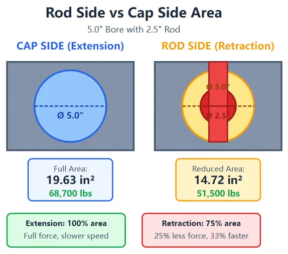
You’ve got 25% less area working during retraction. At the same pressure, that means 25% less force. For boom cylinders lowering a load, gravity helps so reduced retraction force usually doesn’t matter. For arm or bucket cylinders working against back pressure or trying to pull through sticky material, that force loss can be noticeable.
The flip side is speed. Because the rod-side area is smaller, it needs less oil volume to retract. That same cylinder will retract 33% faster than it extends at the same pump flow rate. Operators generally like faster retraction since it’s non-productive motion—you’re just repositioning for the next digging cycle.
Thicker rods give you better column strength and resist buckling under side loads, but they exaggerate the force and speed differences between extension and retraction. Thinner rods keep the forces more balanced but increase the risk of rod bending if the cylinder sees off-axis loading.
There’s no universal answer. It depends on how your cylinder is mounted and what loads it sees. For boom cylinders with long extended lengths, we often recommend thicker rods—maybe 45-50% of bore diameter—to prevent buckling. For bucket cylinders that are well-supported throughout their stroke, thinner rods work fine and keep retraction force higher.
Rod buckling happens when compressive forces exceed the rod’s column strength. The rod bends or bows, which causes side loading on the seals and bearings, which leads to leakage and premature failure.
The critical buckling load depends on rod diameter, extended length, and how the rod is supported. For a 2.5-inch diameter rod with 60 inches of extended length, the critical buckling load is somewhere around 28,000 pounds. If your cylinder is generating 35,000 pounds of force in compression, that rod will buckle eventually.
This is where cylinder manufacturers sometimes create problems by using undersized rods to save material cost. A rod that’s 5% thinner in diameter loses 10% of its buckling strength. You might not notice the issue during initial testing, but after 500 hours of operation with thousands of load cycles, the rod starts developing a permanent bow. Seals wear unevenly. The cylinder starts weeping oil from the rod seal. Eventually it fails completely.
We’ve seen this happen with boom cylinders on larger excavators—45-ton and up—where the extended rod length gets long enough that buckling becomes a real concern. Our standard approach for those applications is calculating the actual buckling load based on mounting geometry and extended length, then sizing the rod with at least 40% margin above the peak compressive force the cylinder will ever see.
You can calculate the perfect bore, specify exactly the right rod diameter, and build a cylinder that delivers ideal force—and it can still disappoint operators if you ignore pump capacity.
Your pump delivers a fixed flow rate, measured in gallons per minute. That flow gets divided among whatever cylinders are operating. When an operator extends the boom, the control valve directs all available pump flow to the boom cylinders. They move at a speed determined by how much oil they receive.
Cylinder speed = Pump flow ÷ Cylinder volume
For a 5-inch bore cylinder:
That same cylinder at the same flow rates but with a 4-inch bore moves significantly faster because it needs less volume per inch of travel.
This creates a fundamental trade-off in excavator hydraulic system design. Larger bores give you more force but require more flow to maintain speed. Smaller bores move faster but sacrifice force. You can’t optimize both unless you’re willing to upgrade pump capacity, which increases cost, power consumption, and heat generation.
There’s a clever workaround that works for many cylinder applications: regenerative circuits. Instead of dumping the rod-side return oil back to tank, route it into the cap side of the cylinder. You’re adding that return flow to the pump flow, effectively increasing the oil supply without actually upgrading the pump.
For a 5-inch bore, 2.5-inch rod cylinder:
If your pump supplies 25 GPM and you add 0.636 GPM from regeneration, the cylinder sees 25.636 GPM effective flow. That’s only a 2.5% speed increase, which doesn’t sound impressive until you realize the return flow scales with cylinder size. Larger cylinders with bigger rods return more oil, which creates bigger speed gains.
The limitation is that regenerative circuits only work in one direction—typically extension. You can’t regenerate during retraction because there’s no return flow to capture. For boom and arm cylinders where extension speed matters more than retraction speed, this works perfectly. For applications where you need balanced speed in both directions, regeneration doesn’t help.
We use regenerative circuits frequently on custom cylinder designs where the customer wants the force of a larger bore without accepting slower cycle times. It adds complexity to the valve design and requires slightly higher pump pressure (since you’re pressurizing both sides of the piston simultaneously), but it solves the force-speed trade-off without requiring expensive pump upgrades.
Undersized cylinders generate heat. Not a little bit of heat—enough heat to shorten oil life, degrade seals, and eventually damage hoses and other system components.
Here’s how it happens: Your operator extends a cylinder that’s too small for the load. The cylinder can’t generate enough force to move the load at full system pressure. So the pump keeps running, building pressure until it hits the relief valve setting. The relief valve cracks open and diverts excess flow back to tank. All that diverted flow represents wasted hydraulic power that converts directly to heat.
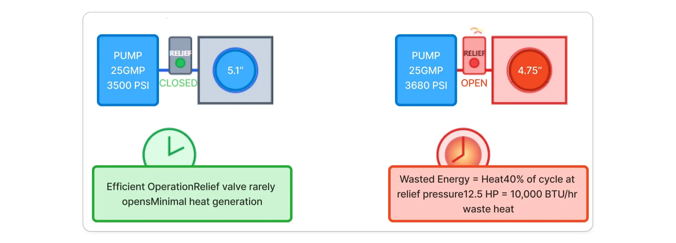
The numbers are striking. A 25 GPM pump operating at 3,500 PSI represents about 50 horsepower of hydraulic power. If your relief valve is open and bypassing even 25% of that flow, you’re generating 12.5 horsepower of waste heat. That’s roughly 10,000 BTU per hour dumping into your hydraulic oil.
Oil temperatures climb. Viscosity drops, which reduces lubrication effectiveness and increases internal leakage. Seals age faster from thermal cycling. Hoses become brittle. Eventually something fails—usually seals first, then pumps, then hoses.
I’ve seen systems where the oil temperature ran consistently above 180°F during normal operation because the boom cylinders were undersized by just 0.4 inches. The customer added an oil cooler to manage the temperature, which cost $3,200 plus installation. We replaced the cylinders with properly sized units for $4,800 total. Oil temperature dropped to 155-160°F under the same working conditions. They removed the oil cooler because it was no longer necessary.
The cylinder upgrade paid for itself in reduced fuel consumption within four months, then continued saving money by extending oil change intervals and reducing seal failures.
Most procurement specs focus on bore, stroke, and pressure rating. Fair enough—those are the critical performance parameters. But the materials and construction details determine whether a cylinder delivers its rated performance for 2,000 hours or 8,000 hours.
Tube material is where manufacturers cut corners. Mild steel tubing costs less than high-strength alloys, so budget cylinders use mild steel and compensate with thicker walls. That adds weight. A cylinder tube made from ST52 or 4140 steel can handle 5,000 PSI with 20-25% thinner walls than mild steel. For a 5-inch bore, 40-inch stroke cylinder, that’s 8-12 pounds of weight savings.
It doesn’t sound like much until you’re mounting cylinders on a boom where every pound of cylinder weight reduces payload capacity by a pound. We’ve built cylinders for specialized excavator attachments where weight was critical—demolition tools, long-reach configurations—and high-strength tube material let us meet strength requirements while staying within weight budgets.
Rod chrome quality varies dramatically between manufacturers. Some use decorative chrome that’s 0.0003-0.0005 inches thick. It looks good, provides some corrosion resistance, but wears quickly under working conditions. Industrial hard chrome should be 0.001-0.002 inches thick with a surface hardness above 68 Rc. That extra thickness and hardness means the rod can withstand thousands of cycles of seal contact without developing wear grooves that lead to leakage.
We specify hard chrome on all our cylinders. The cost premium is about 15%, but it typically doubles the service life before the rod needs replating. For a $1,200 cylinder, that’s an extra $180 upfront to avoid a $600 rod replacement and 8 hours of downtime after 3,000 hours of service. The math is obvious.
Seal selection depends on your operating environment. Standard nitrile rubber seals work fine in clean systems with oil temperatures below 180°F. They cost less and have been the industry standard for decades. But if you’re working in hot environments—desert mining operations, for example—or if your system runs contaminated, nitrile seals don’t last.
Polyurethane seals handle higher temperatures and abrasion better than nitrile. PTFE (Teflon) seals work in extreme temperatures and highly contaminated environments. Viton seals resist chemical attack for cylinders exposed to aggressive fluids. Each seal material has trade-offs in cost, friction, and longevity. We walk customers through these choices based on their specific operating conditions rather than defaulting to whatever seals are cheapest.
Internal stroke cushions decelerate the piston near the end of travel instead of letting it slam into the end cap at full speed. Without cushioning, every stroke ends with a metal-on-metal impact that creates noise, vibration, and accelerated wear on the piston, end cap, and mounting points.
Cushioning adds maybe 10-12% to cylinder cost but can extend service life by 40-50% in applications with frequent direction reversals. Boom cylinders that are constantly raising and lowering benefit enormously from cushioning. Arm cylinders that cycle hundreds of times per shift see measurable reductions in wear and noise with cushioned strokes.
The cushioning mechanism is simple—a tapered section on the piston restricts flow as it approaches the end cap, creating back pressure that slows movement. Then a check valve opens to allow free flow in the opposite direction when the cylinder reverses.
Customers rarely ask for cushioning specifically. It’s not something operators or even most engineers think about. But when we build cylinders for high-cycle applications, we include cushioning by default because the longevity benefit is so substantial. If you’re replacing boom cylinders every 2,000 hours and wondering why, check whether they have stroke cushioning. Odds are they don’t.
We’re starting to see more requests for cylinders with integrated position sensing. Traditionally, if you wanted to know cylinder position, you added an external sensor—usually a string pot or cable extension sensor mounted to the cylinder body. They work, but they’re vulnerable to damage from impact or contamination.
Integrated sensors mount inside the cylinder body, typically using magnetostrictive technology. A magnet attached to the piston moves along the stroke, and a sensing rod measures its position electronically. The sensor output feeds back to the machine’s control system, which can use position data for semi-automated control or to prevent over-extension.
This matters for excavator hydraulic system applications where you’re doing precision work—grading to exact specifications, for example, or operating in confined spaces where you need to limit boom swing or arm extension automatically.
The pozoom engineering team has been developing position-sensing cylinder designs for OEMs building automated excavator systems. The challenge isn’t the sensor technology itself—that’s mature and reliable. The challenge is packaging the sensor inside the cylinder without creating leak paths or compromising pressure ratings. We’ve built cylinders with integrated sensors rated to 5,000 PSI that maintain better than 0.1-inch position accuracy over the full stroke.
Cost premium for integrated sensing is substantial—typically $800-1,200 per cylinder depending on stroke length and output requirements. But for applications where automation or precision positioning matters, there’s no better solution than having position data directly from the cylinder rather than inferring it from valve positions or pump flow.
I’ve seen perfectly calculated, beautifully manufactured cylinders fail in under 1,000 hours because the system oil was contaminated. Dirt particles—even microscopic ones—act like grinding compound between seals and rods. They score the chrome, create leak paths, and accelerate seal wear exponentially.
The industry estimate is that 80% of hydraulic failures trace back to contamination. From our experience repairing and rebuilding cylinders, that number feels low. Contamination is everywhere—it enters through cylinder rod seals, through breather caps on reservoirs, through worn pump seals, even through new oil that wasn’t properly filtered before being added to the system.
Filtration is your primary defense. Most excavators use 10-micron return line filters. That catches the big stuff but lets particles smaller than 10 microns circulate freely. Those smaller particles are what kill seals over time. High-performance systems are moving toward 3-micron or even 1-micron filtration, which costs more in filter maintenance but extends component life dramatically.
We recommend 3-micron filtration as standard for any machine where cylinder longevity matters. The filter elements cost about 40% more than 10-micron filters and need changing slightly more frequently, but seal life typically increases by 60-80%. The math works in your favor—spending an extra $60 per filter change to avoid $1,200 cylinder repairs is obvious.
Wiper seals on cylinder rods are your second line of defense. They scrape dirt, mud, and debris off the rod before it can enter the cylinder. Standard nitrile wipers work in normal environments. Polyurethane wipers resist abrasion better for excavators working in sand, gravel, or other abrasive materials.
For extreme contamination environments—demolition work, mining, trenching in rocky soil—double wipers provide extra protection. The outer wiper removes bulk contamination, and an inner wiper catches whatever passes the first layer. Adding a second wiper increases seal friction slightly and costs about $40 per cylinder, but it keeps contamination out of the cylinder body where it can’t cause damage.
Regular oil sampling tells you what’s happening inside your hydraulic system before you see external symptoms. A spike in wear metals indicates component degradation—possibly cylinder wear, possibly pump wear. Rising particle counts indicate filtration problems or component breakdown. Changing viscosity or acid number suggests thermal breakdown of the oil itself.
We tell customers they should sample oil every 250-500 operating hours depending on how hard they work their machines. The lab analysis costs $25-35 per sample. For a fleet of ten excavators, that’s $250-350 every 500 hours to get early warning of developing problems.
Compare that to the cost of replacing a cylinder after catastrophic failure: $1,200 for the cylinder, $600 for labor, plus 6-8 hours of downtime at $150-250 per hour. One prevented failure pays for a year of oil analysis across the entire fleet.
The trend data matters more than individual samples. A single sample showing slightly elevated iron content might be normal. Three consecutive samples showing increasing iron levels indicates something is wearing—time to investigate before it fails.
Custom hydraulic cylinder components typically cost 20-35% more than catalog equivalents. For a $800 boom cylinder, that’s an extra $160-280. Procurement teams see that premium and default to standard parts to control costs.
But that upfront cost comparison ignores the total ownership picture. Let’s work through an actual example:
Standard cylinder approach:
Custom cylinder approach:
Over 4,200 hours (roughly 2 years of operation):
The custom cylinder saves $3,584 over two years per cylinder. For a two-cylinder boom and two-cylinder arm setup, that’s $14,336 in savings per machine over the same period.
Those numbers assume the standard cylinder lasts 2,200 hours.
. If contamination or excessive heat causes earlier failure—which happens frequently with undersized cylinders—the savings become even more dramatic.
The calculations above include downtime costs, but they’re conservative. We assumed $1,400 downtime cost per failure based on 8 hours at $175/hour. That works for maintenance shops with backup equipment available.
For contractors working fixed-price projects with schedule penalties, downtime costs spike dramatically. A tracked excavator that’s critical to the project schedule might cost $3,000-5,000 per day when you account for rental equipment, schedule delays, and potential contract penalties.
One of our customers operates excavators in remote mining locations. Getting replacement cylinders to site requires air freight because ground transport takes too long. They were spending $800-1,200 per shipment in expedited freight costs every time a cylinder failed. We rebuilt their boom and arm cylinders with upgraded materials and proper bore sizing. Cylinder life increased from 1,800 hours average to over 4,000 hours. They went from 8-10 cylinder failures per year across their fleet to 2-3 failures. The savings in freight costs alone exceeded the premium they paid for custom cylinders.
When you’re ready to move beyond off-the-shelf components, here’s how we approach cylinder specification:
Force requirements come first. Don’t guess. Measure actual loads if possible, or calculate them carefully accounting for linkage geometry, mounting angles, and dynamic factors. Include a safety margin—typically 10-15%—for real-world variations and wear over time.
Operating pressure comes next. Measure actual pressure at the cylinder ports under load, not just the relief valve setting. Pressure drops through valves and hoses mean the cylinder sees less pressure than the pump generates. If you calculate bore based on 3,500 PSI but the cylinder only sees 3,300 PSI under load, you’re undersized by 6%.
Calculate minimum piston area by dividing force by pressure. That gives you the theoretical minimum. Real-world losses—seal friction, internal leakage, pressure drops—typically consume 5-10% of theoretical force, so add margin accordingly.
Check cycle time requirements. Calculate how long extension and retraction will take at your pump’s flow rate. If that’s too slow for operator comfort or productivity requirements, you need to either reduce bore size, increase pump flow, or implement regenerative circuits.
Verify mounting constraints. Can the cylinder physically fit in your available space? Is there clearance for the full stroke? Are the mounting points strong enough to handle the cylinder forces plus any side loading?
Consider environmental factors. Operating temperature range, contamination exposure, and maintenance intervals all affect material and seal selection. A cylinder designed for California desert mining needs different seals than one working in Alaska winter conditions.
Plan for maintenance. Can operators or mechanics access the cylinder for inspection and seal replacement without major disassembly? Some mounting configurations make cylinder removal nearly impossible, which means any cylinder failure causes extensive downtime.
The pozoom technical team works through this process with customers regularly. We’ll often find that the customer’s initial force requirement was based on inaccurate assumptions, or their mounting constraints can be modified slightly to accommodate a better cylinder design. It’s a collaborative process that results in cylinders optimized for the actual application rather than generic solutions that compromise performance.
We’ve built thousands of custom hydraulic cylinder assemblies for excavators, and we keep seeing the same pattern: customers come to us after standard solutions didn’t work. Either the cylinder was too weak and overheated the system, or it was oversized and slowed cycle times, or it fit the specs on paper but failed prematurely in actual service.
The difference in our approach is treating cylinder design as a system-level problem rather than a component-selection exercise. Bore size matters, but it’s connected to pump capacity, valve sizing, heat management, and maintenance practices. Optimizing bore size while ignoring those other factors just moves the problem somewhere else.
We start every project with application analysis. What’s the machine doing? What loads does it see? How long are the work cycles? What’s the operating environment? Those questions reveal requirements that don’t show up in basic force calculations.
Then we look at the complete hydraulic circuit. If your cylinders need to be larger to meet force requirements, do your valves have adequate flow capacity? Are your hoses sized appropriately? Will your oil cooler handle the additional heat if cycle times increase? Sometimes the answer is upgrading multiple components simultaneously. Sometimes it’s finding a creative solution—custom stroke lengths, regenerative circuits, or optimized mounting geometry—that achieves your performance goals without requiring system-wide changes.
The engineering support includes system-level pressure drop analysis, thermal modeling, and fatigue life calculations. We’re not just selling cylinders. We’re solving the problem you hired the cylinder to solve, which sometimes means recommending a smaller cylinder than you asked for, or suggesting changes to other system components, or explaining why your target performance isn’t achievable within your budget and helping you find the right compromise.
For procurement teams managing equipment fleets, we provide detailed cost-of-ownership analysis comparing standard versus custom solutions over realistic service intervals. The numbers usually favor custom designs, but not always. If your application truly matches what standard cylinders are designed for, we’ll tell you that and save you money rather than pushing custom work unnecessarily.
Getting bore size right isn’t complicated once you understand what variables matter and how they interact. Force equals pressure times area—that’s the foundation. But real-world cylinder performance depends on pump flow, mounting geometry, operating temperature, contamination levels, and how the cylinder integrates with the rest of the hydraulic system.
The contractors and fleet managers we work with who get this right are the ones who treat cylinder specification as an engineering decision rather than a purchasing transaction. They measure actual loads and pressures instead of guessing. They account for real-world losses and operating margins. They think about lifecycle costs instead of just upfront prices.
Those decisions pay off in reduced fuel consumption, fewer failures, less downtime, and longer service intervals. An excavator with properly sized cylinders runs cooler, responds better, and costs less to operate over its lifetime.
If you’re dealing with cylinder failures, overheating systems, or machines that just don’t feel right despite being “within spec,” the bore size is likely wrong for your application. Measuring actual operating pressures and forces will tell you what you actually need rather than what the catalog suggests.
We’re here to help with that analysis. The custom hydraulic design process starts with understanding your requirements—not just the numbers, but the actual work environment and operating conditions. From there, we can engineer cylinders that deliver the performance your application needs without the compromises that come with off-the-shelf components.