
There is a pattern that repeats in service calls almost every week. A machine loses pressure or slows down. Someone orders a new pump. The pump arrives, gets installed, and the gauge still reads low. Now a second pump is on order, and nobody has stopped to ask the question that actually matters: where is the oil going?
In one case we handled through our parts and technical support line, a fabrication shop had already replaced a variable-displacement piston pump — roughly a $3,800 unit — on a press brake that had been losing clamping force for weeks. Pressure was still well below setpoint after the swap. The actual fault turned out to be a pilot-operated relief valve with a cracked pilot piston seat, dumping flow to tank below the system's working pressure. One cracked seat. A pump that never needed replacing.
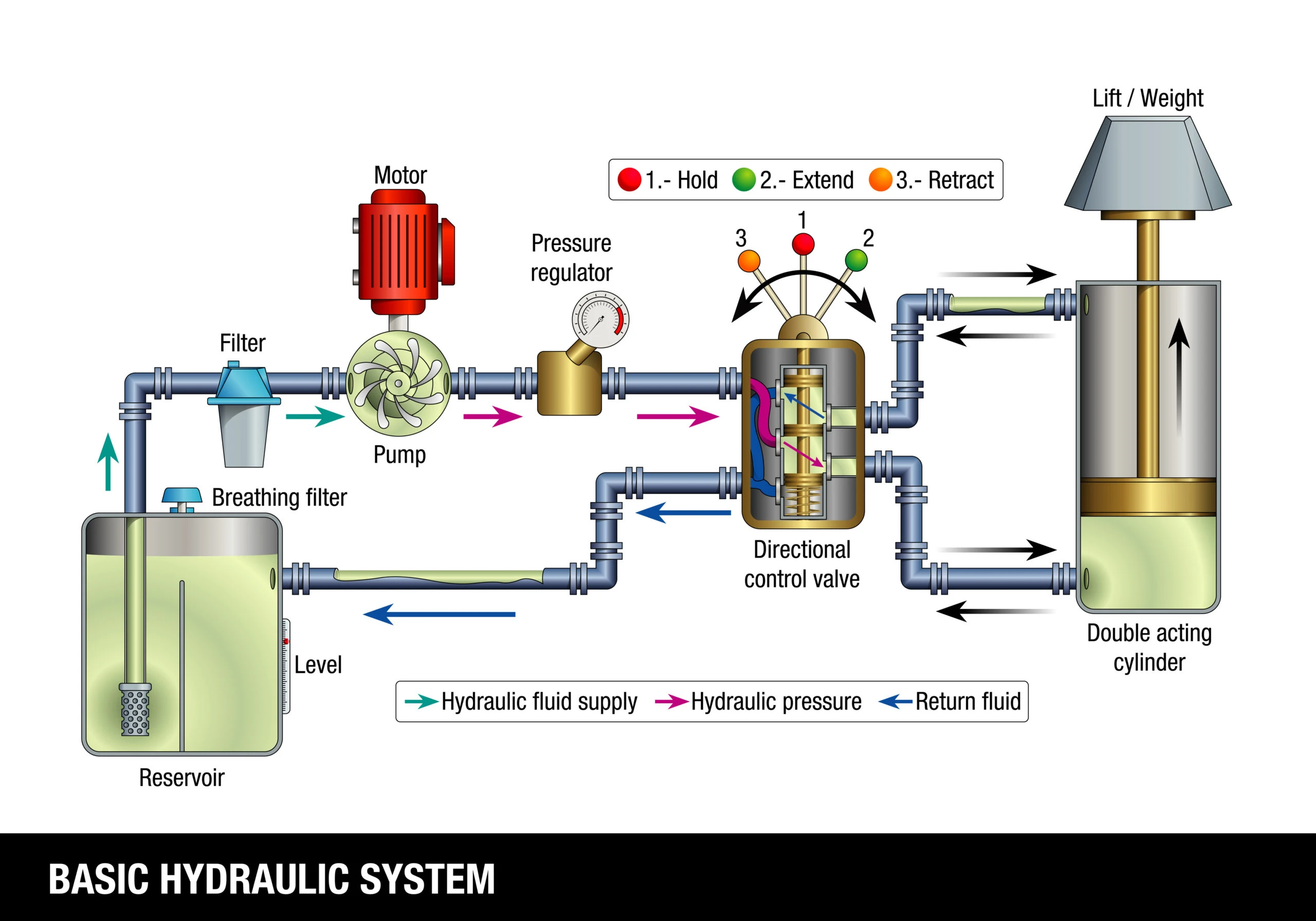
That outcome is not unusual, and it always traces back to the same root misunderstanding: a hydraulic pump creates flow, not pressure. Pressure is the result of that flow meeting resistance downstream — from a loaded cylinder, a valve restriction, or backpressure from a motor. When the gauge reads low, the productive question is not "what's wrong with the pump?" It is "where did the resistance go?" If you take one thing from this article, let it be that shift in thinking. It changes every diagnosis that follows.
This takes thirty seconds at the machine and saves hours downstream. Get it wrong here and every subsequent test points in the wrong direction.
A pressure problem means the system cannot build enough force. A cylinder stalls before reaching full extension under load. A press stops short of its rated tonnage. The gauge peaks well below the relief valve setting. In these situations, oil is bypassing somewhere it shouldn't — past a worn cylinder seal, through a stuck-open valve spool, or over a misadjusted relief. Your job is to find the bypass path.
A flow problem means the system moves, but too slowly. Cycle times have stretched. An actuator that extended in four seconds now takes seven. The machine still develops force — it just can't get the oil there fast enough. Here the investigation shifts toward pump output, suction-side restrictions, clogged filters, or contaminated valve passages that are choking volume through the circuit.
Intermittent faults are harder. A hydraulic motor that stops rotating for a few seconds and then resumes could look like either category. In industry case studies documented by hydraulic consultants, this exact symptom has traced back to an electrical fault — a loose wire causing an amplifier card's power supply to intermittently drop below its threshold voltage, de-stroking the pump to zero output. The fix was electrical, not hydraulic. But identifying it as a flow problem (motor stopped, pressure was normal when checked) pointed the diagnosis toward the pump's displacement control rather than toward valves or actuators. Classification matters.
Operators are the most underused diagnostic resource on any job site. They know how the machine sounds on a normal shift. They notice when a pressure reading drifts or a cycle feels sluggish two days before anyone calls maintenance. Talk to them before you open a toolbox.
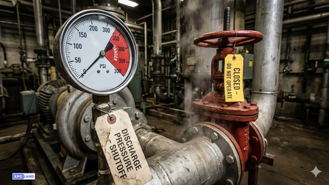
Then document the basics. Record system pressure at every available gauge point — not just the main system gauge. Note hydraulic fluid temperature, because a system running at 170°F behaves very differently from one at 110°F; viscosity drops with heat, and internal leakage rates increase across every component. Check fluid level and condition. Review any recent work — filter changes, component swaps, pressure adjustments.
Here is a point that comes up in our technical support conversations more often than it should: if a component was recently replaced, verify the exact part number. One letter or digit difference in a valve model number can mean the replacement has a different spool configuration, a different pressure rating, or a different flow path. We have seen cases where a positioning fault on a large press persisted for hours because the replacement control valve had a single-character part number variation that made it functionally incompatible with the circuit. Always confirm the full model string before assuming the new part is correct.
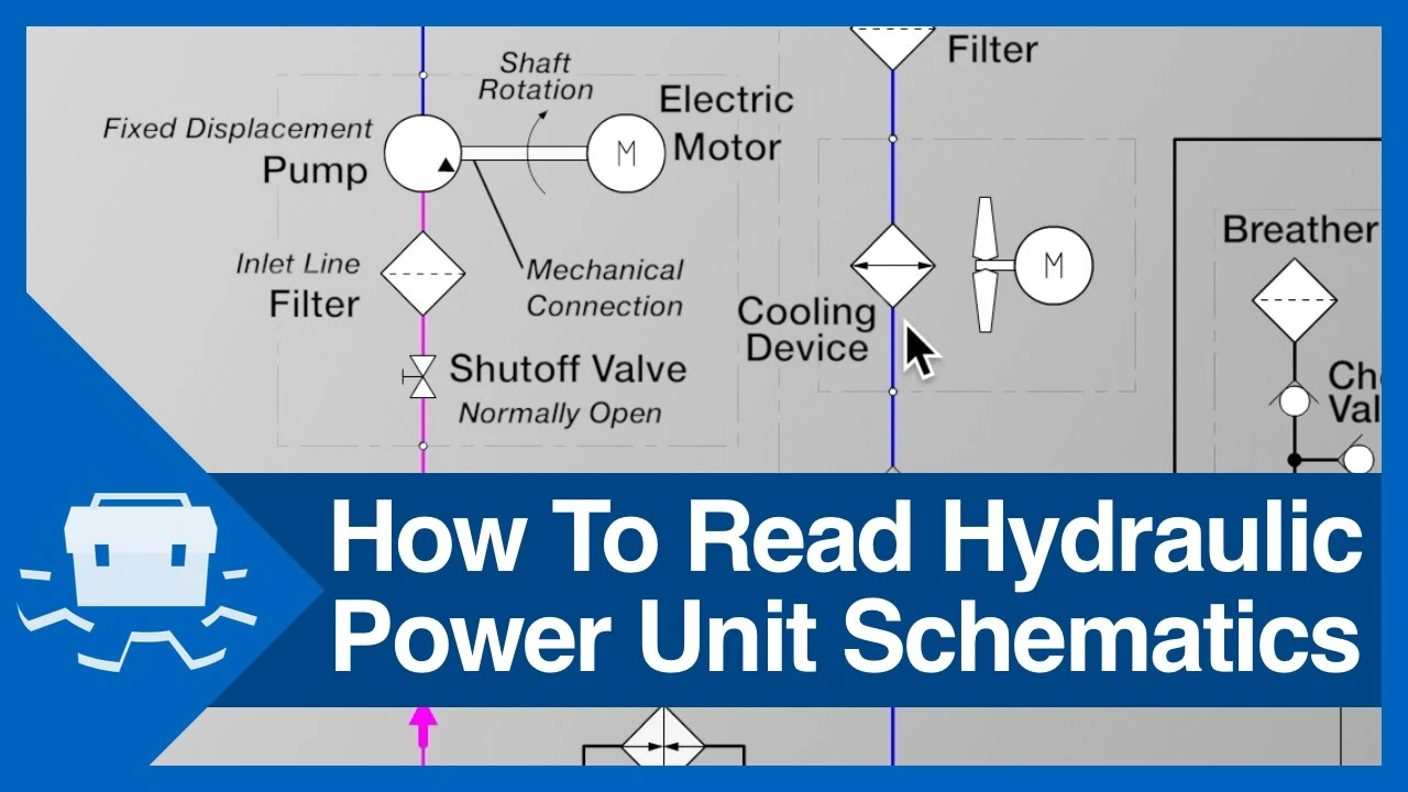
If you haven't pulled out the schematic, you haven't started troubleshooting. That is not an exaggeration. The time you spend tracing a hydraulic system diagram on paper is consistently the most productive time in the entire diagnostic process. Valves buried inside manifolds or tucked behind structural members are invisible during a walk-around but clearly identified on the schematic. Following the oil path from pump to actuator and back to tank, on paper, regularly reveals the fault before a wrench is ever picked up.
Industry experience backs this up. In a well-documented case from a wood products plant (cited by GPM Hydraulic Consulting), a stacker that was supposed to operate at both fast and slow speeds could only run in slow mode. Multiple trades had been working the problem. When someone finally retrieved the schematic, it showed a solenoid-operated valve that had to be energized for the fast cycle. A blown fuse on that single solenoid was the entire problem. The plant could have saved most of the downtime if the schematic had been the first thing consulted.
If your facility keeps schematics locked in an office or buried in a filing cabinet, fix that now. Laminated copies mounted at or near the machine pay for themselves the first time a fault needs tracing.
This is the single most efficient test in hydraulic troubleshooting, and it should be standard procedure on every pressure-loss call. The concept is simple: isolate the pump and relief valve from everything downstream by closing a manual shutoff valve or capping a line. Then start the pump and watch the gauge.
Three outcomes are possible, and each one tells you exactly where to go next.
If pressure climbs to the relief valve setting and holds, the pump and relief are both healthy. Stop investigating them. The fault lives downstream — in a directional control valve, a cylinder, or a motor. Your next move is to isolate individual circuit branches one at a time until pressure recovers, which tells you which branch contains the leaking component.
If pressure builds but won't reach the relief setting, the pump has lost volumetric efficiency — worn internals, a damaged rotating group, or excessive case drain leakage. Confirm by measuring case drain flow; if it exceeds the manufacturer's specification (typically listed in the pump's technical datasheet), the pump needs rebuild or replacement.
If pressure barely builds at all, suspect the relief valve first. A relief valve that is stuck open or set far too low will dump all pump output to tank before pressure can develop. Check the tank return line from the relief valve with an infrared temperature gun — it should be near ambient temperature. If that line is running hot, the relief is passing flow continuously. This check takes sixty seconds and prevents unnecessary pump replacements.
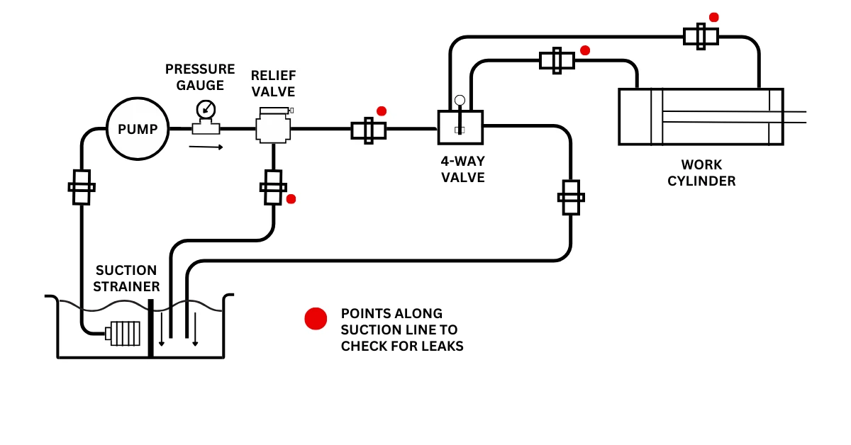
If you haven't checked the suction side, you have not yet addressed the most common field failure in hydraulic pump systems. Cavitation damage begins when the suction path cannot deliver a full, air-free column of oil at the rate the pump demands. Vapor pockets form inside the pump, travel into the high-pressure zone, and implode against internal surfaces with enough energy to erode hardened steel.
The tricky part is that the symptoms — increased noise, pressure loss, erratic actuator motion — overlap with several other fault types. That overlap is precisely why cavitation often goes undiagnosed until the pump is opened and the pitting is visible. On new systems, suction strainer clogging can start within hours as manufacturing debris circulates. On systems that have been running for years, the usual suspects are a partially collapsed inlet hose (the inner liner swells inward, restricting flow without any external sign), a reservoir level that has dropped just far enough to create a vortex above the strainer, or fluid that is too viscous for the ambient temperature during cold-start conditions.
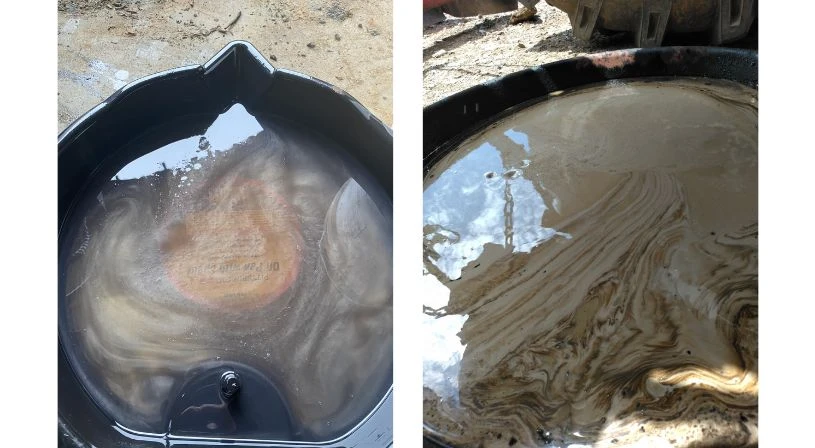
Fluid contamination — particles, water, and air — is widely cited across industry sources (Parker Hannifin, Bosch Rexroth, and multiple IFPS publications) as the root cause of 70–80% of hydraulic component failures. That number deserves respect. It means that more often than not, the real troubleshooting answer is not a broken part but degraded fluid that has been quietly wearing down every component in the circuit for months.
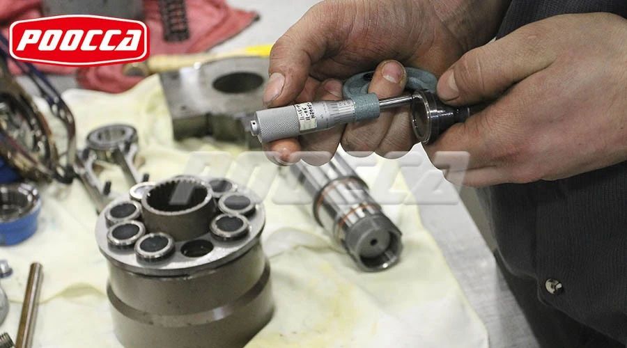
A visual check catches the obvious: dark or milky fluid, foam on the reservoir surface, a burnt smell. But real diagnostic value comes from oil analysis. The numbers that matter are viscosity at operating temperature, particle count per the ISO 4406 cleanliness code, water content in parts per million, and acid number to gauge oxidation. Particle contamination is especially damaging to tight-tolerance components — spool valves and axial piston pump rotating groups will show accelerated wear long before any visible symptom appears on a pressure gauge.
One thing worth saying plainly: new oil is not necessarily clean oil. Fluid from drums or bulk storage regularly exceeds ISO cleanliness targets for precision hydraulic systems. Pre-filtering through a dedicated transfer cart before the oil enters the reservoir is basic practice. Skip it, and you may introduce more contamination in a single fill-up than the system accumulates in months of normal operation.
Internal leakage is the fault mode that produces the most expensive misdiagnoses. Oil bypasses across a worn valve spool, past a blown cylinder seal, or through eroded pump clearances. The machine still moves — just slower, weaker, and hotter. Unlike an external drip on the floor, internal bypass leaves no visible evidence. It shows itself through temperature differentials and pressure drop-off under load.
An infrared camera or temperature gun is the right tool here. Sweep the tank return lines throughout the circuit. Lines that should be at ambient temperature but read 20°F or more above their neighbors indicate a component passing oil internally. In a well-known industry case study, a plywood plant running four prepress rams could only build 1,400 PSI when 2,100 was needed. Thermal imaging showed one ram's supply line running significantly hotter than the other three. When a manual valve was installed on that line and closed, system pressure immediately returned to 2,100 PSI. The prefill valve for that one ram had been stuck open, silently routing the pump's entire output to tank.
The lesson is worth underlining: if you are troubleshooting a hydraulic pressure loss and you do not own a temperature gun, go buy one before you buy another replacement component. A $150 diagnostic tool prevents $5,000 parts-changing exercises.
Replacing parts without test data is not troubleshooting. It is guessing with a purchase order. Every component change should be preceded by a measurement that implicates that specific component.
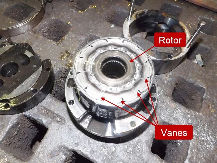
Once the previous steps have narrowed the fault to an area of the circuit, the component inspection becomes targeted. For pumps, check the rotating group for scoring, bearing wear, and seal condition — and measure case drain flow against the OEM spec to quantify internal leakage. For valves, look for spool contamination, scoring, or sticking. For cylinders, inspect rod seals and piston seals; worn seals allow bypass that shows up as drift under load or reduced extension force.
Electro-hydraulic and proportional valves add a layer that catches people off guard. Signal problems, sensor drift, or partial amplifier card failures can produce symptoms that look purely hydraulic. Before condemning a valve, verify that the electrical input is within specification. A multimeter and the manufacturer's wiring diagram belong in the troubleshooting toolkit alongside pressure gauges and flow meters. If the solenoid voltage is right and the valve still isn't shifting, then you have a hydraulic fault. If the voltage is wrong, stop pulling hydraulic components and go find the electrical problem.
For context on how each component type interacts within a complete circuit, our technical overview of the five main components of a hydraulic system covers the relationships and failure cascades between reservoir, pump, valves, actuators, and pressure regulation.
Overheating is both a symptom and a cause, and that dual role is what makes it dangerous. Elevated fluid temperature drops viscosity. Lower viscosity increases internal leakage across every component. More leakage generates more heat. Left unchecked, this feedback loop accelerates seal degradation and fluid oxidation until multiple components fail in quick succession — and by that point, the repair bill is no longer about one part.
Start with the cooler. Is it clean? Are the fins unobstructed? Is airflow or coolant flow adequate? Then check accumulator dump valves — a partially open manual dump valve creates a continuous bypass to tank, generating heat without doing useful work, and it is easy to miss during a visual walk-around.
The most instructive overheating case widely cited in hydraulic training literature involved a system running at roughly 320°F — far beyond any safe operating range. The root cause was a relief valve set below the pump compensator pressure, which forced all pump output continuously across the relief to tank, converting hydraulic energy directly into heat. Setting the relief valve 250 PSI above the compensator and closing a partially open dump valve that had also been contributing brought the temperature down to approximately 130°F within 24 hours. Two adjustments. No parts replaced. The system had the components it needed the whole time — the settings were simply wrong.
Once the repair or adjustment is made, confirm it. Check that system pressure, flow rate, and cycle time are back within specification. Listen for residual abnormal noise. Verify that fluid temperature stabilizes in the normal operating range and does not creep back up over the next several hours.
Then do what almost nobody does, and what separates the shops that keep machines running from the shops that keep fixing the same machines: record the data. Pressure readings at each gauge point. Temperature at the reservoir, pump case drain, and key return lines. Filter condition indicator status. Accumulator pre-charge pressures. Electric motor current draw. This documented baseline becomes the most valuable diagnostic reference you have the next time something drifts — because you will have a clear, timestamped picture of what "normal" looked like for that specific machine.
Scheduled reliability checks do not need to be elaborate. A monthly walk-around with a temperature gun and a pressure log, consistently performed, catches developing problems while they are still cheap to fix. The alternative is waiting for the failure, and by then, the troubleshooting is reactive, the downtime is unplanned, and the cost is always higher.
Swapping parts without measurements tops the list. We field this scenario regularly through our technical support line — a customer calls looking for a replacement pump, and after a few questions it becomes clear that no dead-head test was performed and no one has checked the relief valve. The pump may be perfectly healthy. The diagnosis should come before the purchase order.
Ignoring the suction side is a close second. Maintenance teams that focus exclusively on pressure gauges and delivery components overlook the reality that many pump failures originate at the inlet. A restriction, an air leak, or fluid that is too viscous for the conditions will destroy a pump from the inside out — and the replacement pump will fail the same way if the suction problem is not addressed first.
Treating the schematic as optional is the third. A schematic is not a reference document for design engineers. It is a diagnostic tool for the people who keep the machine running. Every troubleshooting job that skips the schematic takes longer than it needs to.
Not without isolating the pump first. Run a dead-head test: block everything downstream of the relief valve and see if the pump reaches the relief setting. If it does, your pump is fine — the fault is somewhere else in the circuit. The majority of low-pressure cases we see trace back to bypass problems downstream, not to the pump itself.
Use an infrared temperature gun to compare tank return line temperatures across the system. A line that reads significantly hotter than its neighbors points to a component passing oil internally. You can also load-test branches individually — isolate one at a time with a manual valve, and watch for pressure recovery. When pressure returns after closing off a particular branch, the leaking component is in that branch.
Hidden causes include a relief valve set below the pump compensator (creating continuous bypass to tank), a partially open accumulator dump valve, undersized or fouled coolers, and fluid that has lost viscosity from age or thermal degradation. Any of these can push fluid temperature well above the safe range without producing an obvious component failure.
Almost always. Oil from drums or bulk storage frequently contains more particles than precision hydraulic circuits can tolerate. Pre-filtering through a transfer cart with appropriate micron-rated elements is the standard practice for any system with servo valves, proportional valves, or tight-tolerance piston pumps.
Every 500 operating hours or monthly for heavy-duty continuous systems; quarterly for moderate use. The real value is in trending — watching particle counts, viscosity, and water content over multiple samples. A single result tells you less than the direction the numbers are moving.