Search
Close this search box.

Optimized hydraulic oil tank

How One Manufacturer Cut Downtime 47% With Better Hydraulic Tank Design

When your production line stops, money walks out the door. That's what a mid-sized manufacturing plant in Ohio learned after experiencing five major hydraulic failures in eight months.

Their story shows you what happens when you ignore your hydraulic tank. More importantly, it reveals the exact steps they took to fix the problem.
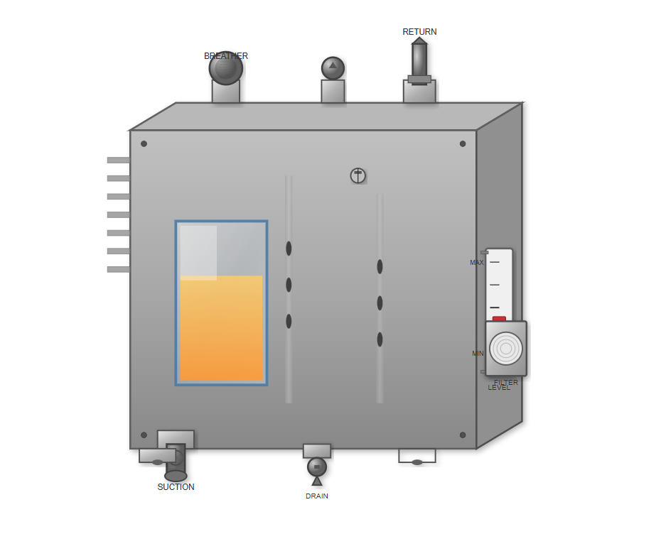
The Problem Nobody Saw Coming

A Pattern of Failures With No Clear Cause

The plant manufactured heavy equipment components. They relied on three main hydraulic systems running 16 hours daily. Everything seemed normal until June 2023.

Their first major breakdown happened on a Tuesday morning. The main press system lost pressure during a production run. The maintenance team found contaminated fluid in the hydraulic tank. They changed the fluid and restarted operations.

Three weeks later, another system failed. Then another. Each failure meant 4-6 hours of downtime. The pattern was clear but the root cause wasn't.

The operations manager brought in a hydraulic systems specialist. What they discovered shocked everyone. The hydraulic tanks had three critical design flaws that nobody had noticed for years.

Hydraulic system failure in manufacturing plant
Inspection Results

What The Inspection Revealed

The specialist spent two days analyzing their systems. His findings painted a troubling picture of long-neglected design issues.

No Proper Baffling System

Returning fluid mixed immediately with pump suction fluid. The turbulence kept contaminants suspended instead of letting them settle.

Poorly Positioned Ports

Fill ports sat directly above the return line. Every time fluid was added, it created a vortex that pulled air into the system, causing pump cavitation.

Undersized Tanks

Tanks were undersized by about 30%. The fluid didn't have enough residence time to release trapped air or allow particles to settle.

Contamination Levels Were Alarmingly High

Fluid samples showed ISO 4406 cleanliness codes of 22/20/17. Industry standards recommend 16/14/11 for their type of equipment.

They were operating at contamination levels five times higher than recommended, dramatically increasing wear and failure rates of critical components.

Excessive contamination leads to premature failure of pumps, valves, and seals, increasing maintenance costs and unplanned downtime.

Financial Impact

The Cost They Didn't See

Before they fixed anything, the operations manager calculated the real cost of their hydraulic tank problems, revealing a much larger financial impact than initially thought.

Total 8-Month Cost

$287,000
  • Direct Downtime Costs

    5 failures averaging 5 hours each

    $210,000

  • Replaced Components

    4 pumps, 6 valve assemblies, seals & gaskets

    $22,540

  • Fluid Replacement

    Three times more frequent than normal

    $12,000

  • Maintenance Labor

    Doubled due to emergency repairs

    $42,460

The Hidden Costs Added Up Faster

Direct costs were obvious. Each breakdown meant lost production time. According to a 2023 Siemens report, unplanned downtime costs companies between $39,000 to $2 million per hour. Their average downtime cost was $8,400 per hour.

Five failures averaging 5 hours each meant $210,000 in direct losses. That's just eight months of data.

Contaminated fluid damaged seals, pumps, and valves. They replaced four pumps at $3,200 each. Six valve assemblies at $890 each. Countless seals and gaskets.

The total cost for those eight months hit $287,000. That's more than the entire hydraulic system was worth.

"We were throwing money at symptoms instead of solving the root cause. The real cost wasn't just in parts and labor, but in lost production opportunities."

— Plant Operations Manager

Unplanned Downtime Cost Comparison

The Fix

The Solution They Implemented

The plant decided to redesign their hydraulic tanks rather than replace the entire system. The specialist recommended a five-phase approach that addressed all root causes.

Tank Modification

They started with proper internal baffling. A vertical baffle separated the return side from the suction side. This gave returning fluid time to cool and degas before reaching the pump inlet.

They repositioned all ports. The return line now entered near the bottom on the return side. The suction line drew from the bottom on the opposite side. Fill ports moved to the top center, away from both return and suction areas.

1
2

Capacity Adjustment

They couldn't easily increase physical tank size, so they reduced system pressure by 8% and optimized cycle times. This effectively increased the fluid residence time in the tank by 25%.

Filtration Upgrade

They added a dedicated offline filtration circuit for each tank. A small pump circulated fluid through 3-micron filters continuously, even when the main system was idle.

Return line filters were upgraded from 25-micron to 10-micron beta 200 rated filters. This caught particles before they entered the tank.

3
4

Breather System

Old breather caps were replaced with desiccant breathers rated for their fluid flow rates. These prevented moisture and airborne contaminants from entering during thermal breathing cycles.

Monitoring System

They installed real-time contamination monitors on each tank. These sensors tracked particle counts and sent alerts when levels exceeded ISO 16/14/11.

5

Implementation Timeline

The entire modification took six weeks. Three weeks for parts procurement and three weeks for installation, done during scheduled maintenance windows to minimize production impact.

Outcomes

The Results Nobody Expected

The changes delivered impressive results within the first month, with continued improvements over time.

Contamination Reduction

From 22/20/17 to 15/13/10

Fluid contamination dropped to cleaner than their target specification, extending component life dramatically.

Component Failures

↓ 73%

They went from replacing pumps monthly to replacing them once in six months, drastically reducing parts costs.

Maintenance Costs

↓ 41%

Reduced emergency repairs meant maintenance teams could focus on preventive work instead of constant firefighting.

Downtime Reduction

↓ 47%

From five failures in eight months to just one failure in the next eight months.

Fluid Change Intervals

6 → 18 Weeks

Improved contamination control meant fluid stayed usable three times longer, reducing replacement costs.

Production Efficiency

↑ 12%

Systems maintained consistent pressure and response times throughout shifts, improving overall output.

Impressive Return on Investment

The payback period was just 11 months. After that, every dollar saved went straight to their bottom line.

A $15,000 investment in tank modifications saved them $287,000 in the first year alone. That's an impressive 19:1 return on investment.

But the real value wasn't just money saved. It was production reliability restored, maintenance staff spending time on improvements instead of emergency repairs, and operators confident their equipment would run when needed.

Key Insights

What Made This Work

Three critical factors drove their remarkable success and can be applied to any hydraulic system improvement project.

Root Cause Analysis

They committed to understanding the root cause instead of applying quick fixes. Changing contaminated fluid treated symptoms, not causes.

Systematic Approach

They followed a systematic approach where each phase built on the previous one. Upgrading filters without fixing tank design would have wasted money.

Monitoring Implementation

They implemented monitoring because you can't manage what you don't measure. Real-time data helped them spot developing problems before they caused failures.

"The hydraulic tank market is projected to grow from $19.04 billion in 2023 to $30.7 billion by 2030, which signals increasing recognition of proper tank design. But growth doesn't help if you don't apply the fundamentals correctly."

— Plant Operations Manager

They also learned that tank size matters less than tank design. A well-designed smaller tank outperforms a poorly-designed larger tank every time.

The global industrial hydraulic equipment market was valued at $37.5 billion in 2024 and is expected to reach $52.6 billion by 2033. That's a lot of equipment relying on properly designed tanks.

Practical Advice

Five Things You Can Check Today

You don't need a consultant to spot basic hydraulic tank problems. Here's what to look for to identify potential issues in your own systems.

Check Your Fluid

Pull a sample and have it analyzed. If your ISO code is above 18/16/13, you have a contamination problem.

Cost: ~$45 per sample

Look At Your Return Line

Watch where returning fluid enters the tank. If it creates visible turbulence, your baffle design needs work.

Cost: Free

Measure Fluid Temperature

If your fluid runs above 140°F consistently, your tank doesn't have enough heat dissipation capacity.

Cost: ~$50 for thermometer

Inspect Your Breathers

Pull your breather cap and look inside. If you see dirt, rust, or moisture, it's not working properly.

Cost: Free

Track Your Failures

Keep a log of every hydraulic problem. Frequent seal or pump replacements indicate contamination issues.

Cost: Free
Key Takeaways

Lessons That Apply Everywhere

This manufacturing plant wasn't special. They faced problems that affect thousands of facilities running hydraulic equipment.

Their success came from treating the hydraulic tank as a critical component instead of a simple fluid container. The tank does four jobs: stores fluid, removes heat, releases air, and settles contaminants. Poor design compromises all four functions.

The global industrial hydraulic equipment market was valued at $37.5 billion in 2024 and is expected to reach $52.6 billion by 2033. That's a lot of equipment relying on properly designed tanks.

The economics are straightforward. A $15,000 investment in tank modifications saved them $287,000 in the first year. That's a 19:1 return.

But the real value wasn't just money saved. It was production reliability restored. Maintenance staff spending time on improvements instead of emergency repairs. Operators confident their equipment would run when needed.

The Four Critical Functions of a Hydraulic Tank

  • 1

    Fluid Storage

    Maintains adequate volume for system operation, accommodating fluid expansion and contraction.

  • 2

    Heat Dissipation

    Provides surface area for heat transfer, helping maintain optimal fluid operating temperature.

  • 3

    Air Release

    Allows entrained air to separate from the fluid before it reaches the pump suction.

  • 4

    Contaminant Settling

    Provides residence time for solid contaminants to settle out of the fluid before it's recirculated.

Next Steps For Your Operation

You don't need to redesign your entire hydraulic system to see improvements. Start small and build on your success.

  • Start with one system. Pick the one causing you the most problems. Apply the principles from this case study. Measure the results.

  • Get your fluid analyzed. This gives you baseline data to measure improvements against. Most industrial fluid suppliers offer this service.

  • Talk to your maintenance team. They know which systems fail most often. They see the patterns you might miss from reports alone.

  • Consider the total cost of your current approach. Add up downtime, replacement parts, fluid costs, and maintenance labor. Compare that to the cost of proper tank design.

The manufacturing plant in this case study isn't unique. They just decided to stop accepting failures as normal. You can make the same choice.

Common Questions

FAQ About Hydraulic Tank Problems

Answers to the most frequently asked questions about hydraulic tank design, maintenance, and performance.