
This type of valve belongs to the on-off valve category. There are many varieties, but they share common characteristics: at least three ports (two inlets, one outlet); the spool position (flow path opening/closing) is determined by the pressure at the two inlets; at steady state, only one inlet is connected to the outlet. They can be divided into two types: high-pressure-through and low-pressure-through.
The spool moves under the opposing action of the two inlet pressures, connecting the lower-pressure inlet to the outlet. This is commonly used in closed circuits to discharge hot oil, hence also called a “hot oil discharge valve.”
The graphic symbols for hot oil discharge valves come in various forms; some show 3 states, with dashed lines indicating the middle is a transitional state.
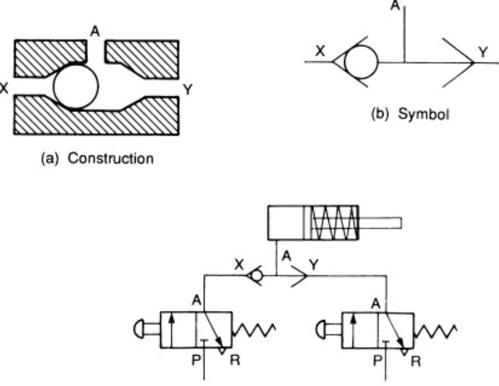
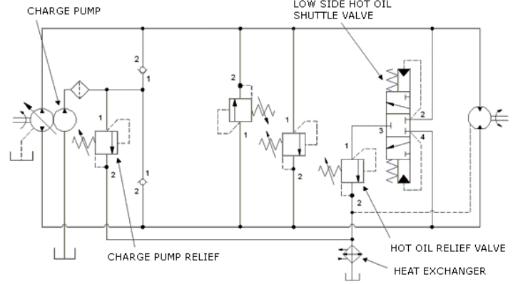
In closed circuits: Auxiliary pump P2 draws cold oil from the tank, which enters the low-pressure side of the circuit (motor return side, usually hotter) through a check valve; the hot oil discharge valve connects the low-pressure side to the relief valve; since this relief valve’s set pressure is lower than the other relief valve, it opens to discharge hot oil; the other relief valve serves only as a safety valve to protect pump P2.
Because continuous hot oil discharge is needed, there are requirements for the pressure differential-flow characteristics of this valve, but response sensitivity requirements are not high.
The spool moves under inlet pressure action, connecting the higher-pressure inlet to the outlet (“fence-sitter” characteristic). Hereafter, “shuttle valve” specifically refers to this type.
ISO 1219-1:2006 recommends corresponding graphic symbols; some manufacturers use different forms to represent ball spools or spool valves, with some spool valves having larger openings.
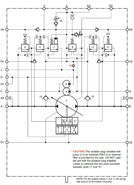
For example, in a system driving 4 actuators, load pressures must pass through multiple shuttle valves, easily causing sluggish response; excavator circuits (7-8 actuators) require multiple standard shuttle valves; using multi-inlet shuttle valves can improve the series-connection sluggishness problem.
When selecting shuttle valves, pay attention to: allowable pressure, pressure differential-flow characteristics, internal leakage. Different scenarios have different requirements: