
Hydraulic systems represent the backbone of modern industrial machinery, powering everything from construction equipment to manufacturing assembly lines. At the heart of these systems lie critical hydraulic parts that ensure optimal performance, longevity, and safety.
When discussing hydraulic systems, most attention focuses on primary components like pumps, motors, and cylinders. However, auxiliary hydraulic parts play an equally vital role in maintaining system health and operational efficiency.
These components work synergistically to filter contaminants, store energy, dissipate heat, connect system elements, and prevent fluid leakage. Understanding the function and specifications of each component category enables engineers and technicians to design, maintain, and troubleshoot systems more effectively.
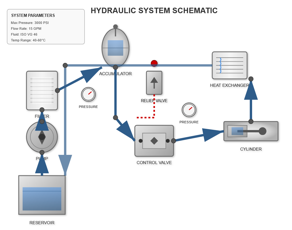
Modern hydraulic components work in perfect synchronization
Handling pressures exceeding 5,000 PSI
Maintaining ISO 16/14/11 standards
Precision techniques for optimal performance
Filtration represents perhaps the most critical function among all hydraulic parts, with studies indicating that approximately 75-80% of hydraulic system failures stem from contamination-related issues.
Modern filtration components typically utilize multi-stage filtration media with beta ratings of β25 ≥ 200, meaning they capture 99.5% of particles larger than 25 microns. High-efficiency units in filtration applications employ synthetic filter media capable of handling flow rates between 10 to 500 liters per minute while maintaining pressure drops below 0.5 bar at rated flow.
Suction filters, pressure line filters, and return line filters each serve distinct purposes within the hydraulic circuit, with pressure ratings ranging from low-pressure applications at 50 PSI to high-pressure systems exceeding 6,000 PSI.

Quality filtration systems should provide service intervals of 2,000-4,000 operating hours under normal conditions.
Among all system components, the hydraulic accumulator stands out for its ability to store pressurized fluid and release it on demand, functioning as energy storage units, surge suppressors, and pressure maintenance systems.
Offer response times under 25 milliseconds and can cycle millions of times without degradation, making them ideal for rapid energy release applications.
Provide larger fluid volumes—ranging from 1 to 200 liters—making them suitable for applications requiring substantial energy release over longer durations.
Serve as compact solutions for systems with limited space, typically handling volumes under 5 liters while providing reliable performance.
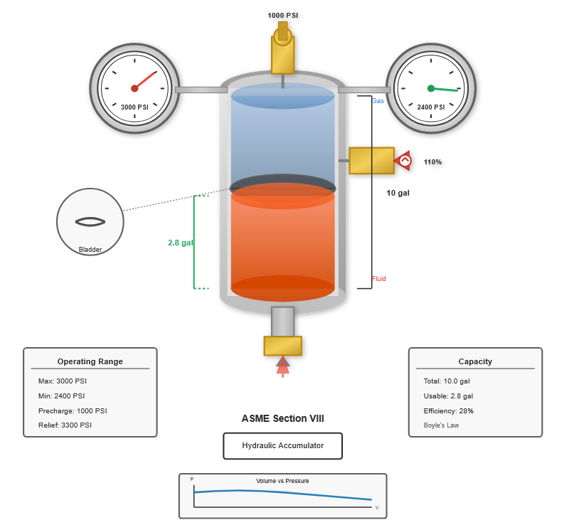
The sizing of hydraulic accumulator components requires precise calculations based on system volume requirements, pressure ratios, and gas precharge specifications. For a system operating between 3,000 PSI maximum and 2,400 PSI minimum working pressure, engineers calculate the required accumulator volume using Boyle's Law.
A typical 10-gallon hydraulic accumulator precharged to 1,000 PSI can deliver approximately 2.8 gallons of usable fluid volume within the pressure range of 2,400-3,000 PSI.
Proper sizing ensures optimal energy storage and release characteristics
Safety considerations make accumulators among the most regulated components in hydraulic systems. ASME Section VIII standards govern accumulator design and manufacturing, requiring pressure relief valves rated at 110% of maximum working pressure.
Annual inspection, complete teardown every 5 years or 10,000 hours
The hydraulic tank represents one of the largest and most fundamental components in any system, performing multiple critical functions beyond simple fluid storage.

These multifunctional units typically range from 50 to 5,000-gallon capacity depending on system size and application. Engineering standards recommend that fluid storage reservoirs should provide capacity equivalent to 3-5 times the pump flow rate per minute.
System Pump Flow Rate
20 GPM
Recommended Tank Capacity
60-100 Gallons
Residence Time
2-3 Minutes
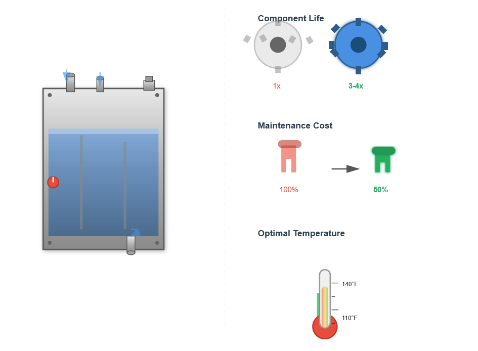
Modern tank construction employs welded steel plate assemblies with internal baffles that prevent fluid turbulence and promote laminar flow. These baffles, positioned to separate pump suction and return line zones, constitute essential elements that prevent fluid churning and minimize aeration.
According to research published by the National Fluid Power Association (NFPA), proper reservoir design and fluid management practices can extend hydraulic system component life significantly while reducing maintenance costs.
300-400% longer service life through optimized fluid management
Up to 50% lower maintenance expenses through proper design
Maintaining fluid temperatures between 110-140°F (43-60°C)
Source: National Fluid Power Association (NFPA Technical Report T3.16.2, 2023)
Temperature control represents a critical challenge in hydraulic system design, making heat exchangers essential for high-performance applications where excessive temperatures can significantly impact efficiency and component life.
Excessive fluid temperatures—above 160°F (71°C)—accelerate oil oxidation, reduce fluid viscosity, degrade seals, and diminish system efficiency by approximately 15-20% for every 15°F increase above optimal operating temperature.
Most common variety utilizing finned tube construction with aluminum or copper fins providing heat transfer coefficients of 10-15 BTU/hr-ft²-°F. Handle heat loads from 5,000 to 500,000 BTU/hr.
Offer superior heat transfer performance with coefficients reaching 150-300 BTU/hr-ft²-°F. Shell-and-tube designs common in industrial settings use brazed plate construction for maximum surface area.
Provide precise temperature control for critical applications where ambient conditions vary significantly or high heat loads must be managed consistently.
Sizing heat exchanger components requires calculating system heat generation based on pump efficiency losses, pressure drops across valves and conductors, and mechanical friction.
Heat Calculation Formula
Heat (BTU/hr) = (Horsepower × 2,545) × (1 - Efficiency)
Where system efficiency typically ranges from 70-85% depending on component selection and operating conditions.
System Power
50 HP
Efficiency
75%
Heat Generation
31,800 BTU/hr
Connection integrity defines system reliability, making hydraulic line fittings among the most critical components in any installation, withstanding extreme pressures, vibration, and thermal cycling.

These seemingly simple components must withstand extreme pressures, vibration, thermal cycling, and chemical exposure while maintaining zero-leakage performance over millions of pressure cycles.
Ubiquitous in mobile and industrial applications, utilizing 37° flared tube ends mating with corresponding seat angles.
Provide superior leakage resistance using elastomeric O-rings captured in machined grooves.
Material selection for fitting assemblies depends on system pressure, fluid compatibility, and environmental exposure. Carbon steel units with zinc plating serve most industrial applications up to 6,000 PSI working pressure.
Sealing devices represent the most diverse category of hydraulic parts, encompassing thousands of designs optimized for specific applications, pressures, temperatures, and fluid compatibilities.
Designed for stationary applications where no movement occurs between sealed surfaces.
Engineered for applications where movement occurs between components.
Hydraulic cylinder seals constitute perhaps the most critical dynamic sealing elements. Rod seals prevent pressurized fluid from escaping along the cylinder rod during extension and retraction cycles.
Utilize pressure-activated design principles where system pressure energizes the seal lip against sealing surfaces. These sealing elements accommodate pressures from 500 to 5,000 PSI.
Prevent fluid bypass between cylinder chambers. Double-acting cylinders require bidirectional sealing components capable of containing pressure from either direction.
| Material Type | Temperature Range | Fluid Compatibility | Durometer Hardness | Key Characteristics |
|---|---|---|---|---|
| Nitrile Rubber (NBR) | -40°F to +250°F (-40°C to +121°C) |
Petroleum-based fluids | 70-90 Shore A | Economical, good general purpose, limited temperature range |
| Fluorocarbon (Viton) | -15°F to +400°F (-26°C to +204°C) |
Synthetic fluids, esters, acids | 75-90 Shore A | High temperature resistance, chemical compatibility, higher cost |
| Polyurethane | -40°F to +200°F (-40°C to +93°C) |
Most hydraulic fluids | 85-95 Shore A | Superior wear resistance, excellent extrusion resistance at high pressures |
| Ethylene Propylene (EPDM) | -60°F to +300°F (-51°C to +149°C) |
Water-based fluids, glycols | 70-90 Shore A | Excellent weather resistance, poor petroleum compatibility |
The true value of hydraulic parts emerges through systematic integration where all components function cohesively, with proper maintenance ensuring optimal performance and longevity.
System designers must consider interactions between components: filter pressure drops affecting pump efficiency, accumulator placement relative to actuators, tank size influencing heat dissipation capacity, and fitting orientation impacting flow turbulence.
A comprehensive approach leveraging multiple component categories achieves target cleanliness levels more effectively than isolated improvements:
Similarly, thermal management integrates multiple elements: heat exchangers actively remove heat, tank surface area provides passive cooling, accumulator placement reduces pressure spike heating, and proper fitting selection minimizes turbulence-related temperature rise. System efficiency improvements of 10-15% are achievable through integrated thermal management strategies.
Maintenance programs for hydraulic parts directly impact system reliability and operational costs. Predictive maintenance strategies monitor key parameters to prevent unexpected failures and optimize service intervals.
Regular maintenance ensures optimal performance and extends component life
Reputable hydraulic equipment supplier organizations provide technical support throughout the specification process, offering application engineering assistance, computational tools for sizing components, and testing data validating performance claims.
Premium components with extended service life often deliver superior value despite higher initial costs, particularly in critical applications where downtime is expensive.