
Principles, Functions & One-Way Control Applications
Hydraulic systems are designed to control energy in motion. Pressure, flow, and direction must be stable, predictable, and safe. Among directional control valves, hydraulic check valves have a simple structure but play an important role.
Hydraulic check valves prevent backflow. They keep fluid moving in the correct direction and help protect components, hold pressure, and stabilize actuator movement. This helps prevent pressure loss, unstable movement, or damage to pumps and motors.
Directional control valves guide hydraulic fluid through the system. By controlling flow, they regulate actuator movements, such as cylinders extending or holding position. Proper flow paths are essential for stable operation.
Check valves differ from spool or solenoid valves. They do not switch flow paths actively. Instead, they automatically allow or block flow depending on pressure. Because of this, check valves are mainly used to support system safety and stability rather than control main flow.
In practice, check valves can be installed at pump outlets, between branches, in return lines, or inside integrated valve assemblies. They always allow flow in one direction and block it in the opposite direction.
A hydraulic check valve lets fluid flow in one direction and stops backflow. It works automatically using fluid pressure, often with a spring-loaded valve element.
It can also be called a hydraulic non-return valve. Names may vary, but the basic operation is the same: the valve opens when the inlet pressure exceeds the set opening pressure. If fluid tries to flow backward, the valve element presses against the seat, blocking the flow.
Although a hydraulic check valve is designed to allow flow in one direction, it is not a zero-resistance component. When fluid passes through the valve, a pressure drop is always present. Pressure drop directly affects system efficiency, heat generation, and actuator response.
The pressure drop across a hydraulic check valve mainly occurs because the flowing fluid must overcome the spring force, internal friction, and flow restrictions inside the valve. Even after the valve is fully open, the flow path is narrower and less streamlined than a straight pipe. This creates turbulence and energy loss, which appears as a pressure drop.
In low-flow or low-pressure systems, the pressure drop may be negligible. However, in high-flow circuits or energy-sensitive systems, an improperly selected check valve can cause unnecessary power loss and increased oil temperature. For this reason, pressure drop should be considered alongside opening pressure when selecting a hydraulic check valve.
In practice, manufacturers provide pressure drop curves showing the relationship between flow rate and pressure loss. These curves are more reliable than nominal values and should be used during system design, especially for continuous-duty or high-flow applications.
The function of a check valve is simple, but it affects the system in many ways. Common functions include:
Check valves usually operate quietly and are not noticeable during normal operation. Their effect becomes clear when pressure changes suddenly, flow stops, or loads act on the system. Without them, short-term pressure fluctuations can cause long-term mechanical issues.
A check valve works based on a balance of forces on its valve element, usually a ball or poppet.
The minimum pressure to open the valve is called the opening pressure. It depends on the spring force, valve weight, friction, and seat area. Choosing the correct valve is important. If the opening pressure does not match system conditions, it can cause vibration, delayed response, or energy loss.
Hydraulic check valves are usually divided into two categories: standard (non-piloted) and pilot-operated.
Standard check valves rely only on pressure difference and spring force.
Common designs include:
They can be installed in pipelines, modular blocks, or base-mounted assemblies.
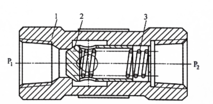
The valve body forms the outer casing of the check valve and is also the main flow channel for the hydraulic oil.
The valve body has an inlet (P₁) at one end and an outlet (P₂) at the other. The valve insert and spring are located in the middle section. The inner surface of the valve body is precision-machined to ensure the coaxial movement of the valve insert and the reliability of the sealing surfaces.
The component shown in the center of the illustration is the valve insert (also called a valve disc or valve insert assembly).
Under hydraulic pressure, the valve insert moves axially, and its front end seals against the valve seat. Once the valve insert is in contact with the valve seat, the flow path is closed, preventing backflow.
This design features an axially guided valve insert, which, compared to a freely supported design, allows for more stable movement of the valve insert and is less susceptible to vibration under medium to high flow conditions.
The valve seat is located in the valve body and is in direct contact with the sealing surface of the valve insert.
When back pressure occurs or system pressure drops, spring force and hydraulic pressure act together to press the valve insert against the seat. This creates a reliable seal and prevents backflow of hydraulic oil.
The machining accuracy of the valve seat directly affects the sealing performance and the service life of the check valve.
The spring is located behind the valve insert and is a key component for the automatic closing function of the check valve.
The main functions include:
The higher the spring stiffness, the higher the pressure required to open the valve and the greater the pressure loss during forward flow.
When hydraulic oil flows from P₁ to P₂, the pressure overcomes the spring force and pushes the valve spool away from the valve seat, creating a flow path. The hydraulic oil flows through the gap around the valve spool to the outlet.
When hydraulic oil attempts to flow from P₂ to P₁, the pressure and spring force work together to press the valve spool firmly against the valve seat. This completely closes the flow path and prevents backflow.
In industrial use, opening pressure is usually 0.04–0.4 MPa and can be adjusted by changing spring stiffness. Performance depends on valve design and system conditions.
Installed at pump outlets, check valves prevent backflow and pressure changes after the pump stops, protecting pumps and motors.
Check valves prevent pressure interference between different branches. This is useful in systems with multiple actuators at different pressures.
In return lines, check valves can maintain back pressure, improving smooth operation and handling load changes.
Check valves are often combined with other valves (throttle, sequence, or flow control) to form assemblies like throttle-check valves or sequence-check valves.
In addition to its basic one-way function, a pilot-operated check valve also allows for controlled reverse flow when needed.
In normal operation, it functions like a standard check valve, allowing flow in only one direction. When a pilot pressure is applied to the control port, the internal piston mechanically opens the valve, thus allowing bidirectional flow.
This design is typically used in load-holding circuits.
The pilot pressure is usually taken from the hydraulic line and must reach a certain percentage of the system pressure to ensure reliable opening. In many designs, this percentage is between 30% and 50%, but the exact value depends on the valve design and manufacturer specifications.
Selecting a hydraulic check valve requires more than just matching nominal pressure and port size. Several operating factors influence its performance.
Proper sizing contributes to noise reduction and extended service life.
Check valves are directional valves. Incorrect installation can obstruct flow or cause malfunctions. Flow direction markings must always be checked during installation and maintenance, especially in circuits connected to pumps or carrier components.
In late 2023, a material handling facility in Ohio experienced repeated pressure losses in its vertical lifting system. Even with normal pressure readings at system startup, the carrier’s hydraulic cylinders slowly lowered during idle operation.
Further investigations revealed backflow in the return circuit under static load. The existing directional control valve was inadequate.
From a system design perspective, selecting a check valve requires considering performance requirements, operating conditions, and overall system costs.
A clear classification of valve categories helps engineers and maintenance teams effectively narrow down the selection. Specialized product lines, such as hydraulic valve solutions, often serve as a reference for system design or component replacement.
Product Availability and Technical Resources: Modern hydraulic systems require components that function reliably under a wide range of conditions. Hydraulic88 offers valve options for common industrial applications, focusing on functionality, application compatibility, and cost-effectiveness.
A well-thought-out valve selection process contributes to smooth system upgrades, maintenance schedules, and component replacements throughout the entire lifecycle of the hydraulic system.
Hydraulic check valves may seem simple, but they play a crucial role in system stability, component protection, and reliable operation. By preventing unwanted backflow, they protect pumps, isolate circuits, and control loads in a variety of applications.
Knowing how different check valves work, where they are used, and how they are installed helps engineers avoid common system issues, thereby improving system reliability and avoiding unnecessary complexity.
Further technical aspects: With the advancement of hydraulic systems, check valves are increasingly being integrated into compact manifolds and control valves. These designs reduce potential leakage points and improve response speed. However, since long-term performance data for some integrated configurations are still being optimized, an application-specific evaluation is essential.