
Based on Pascal's Law, converting hydraulic pressure into powerful linear motion with exceptional control.
Including single-acting, double-acting, telescopic, and tandem cylinders for diverse applications.
Force, pressure, speed, and flow rate relationships critical for proper cylinder selection and design.
From construction equipment to aerospace systems, enabling powerful and precise mechanical operations.
Understanding the fundamental operations and classifications of hydraulic cylinders is essential for proper application and system design.
A hydraulic cylinder operates on Pascal's Law, which states that pressure applied to a confined fluid is transmitted equally in all directions. When pressurized hydraulic fluid enters the cylinder, it pushes against a piston, creating linear motion. This simple yet effective principle allows hydraulic cylinders to generate tremendous forces while maintaining precise control over movement and positioning.
The basic operation involves pumping hydraulic fluid into one side of the cylinder while allowing fluid to exit from the opposite side. The pressure differential across the piston creates the force that drives the piston rod.
The beauty of this system lies in its ability to multiply force through hydraulic advantage, making it possible to lift massive loads with relatively small input forces.
Pressure applied anywhere to a body of fluid causes a force to be transmitted equally in all directions; the force acts at right angles to any surface in contact with the fluid.
Hydraulic cylinder cross-section illustrating pressure differential and piston movement
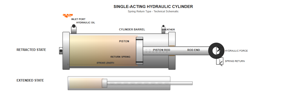
These cylinders use hydraulic pressure for movement in only one direction, typically extension. The return stroke relies on external forces such as gravity, springs, or load weight. They are simpler in design and commonly used in applications like hydraulic jacks and lifting platforms.
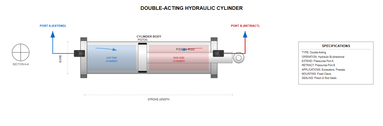
The most versatile type, double-acting cylinders use hydraulic pressure for both extension and retraction movements. This bidirectional capability makes them ideal for applications requiring controlled movement in both directions, such as excavator arms and industrial presses.
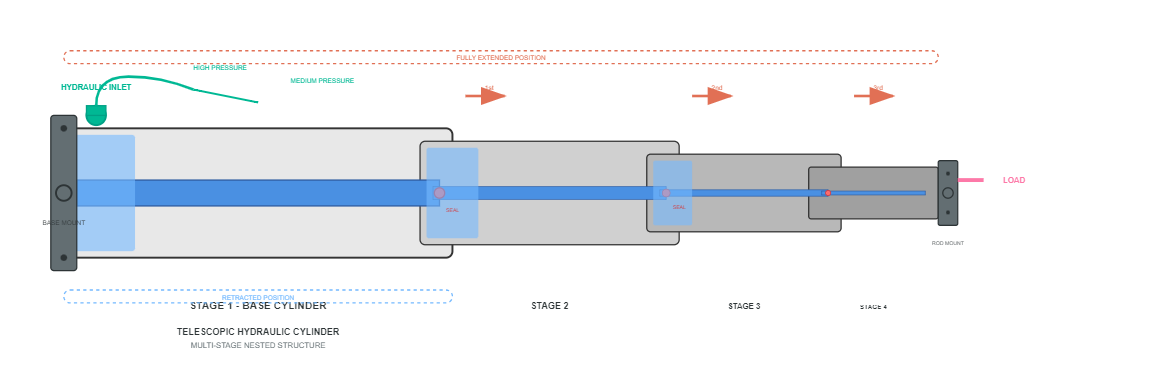
These specialized cylinders feature multiple nested stages that extend sequentially, providing exceptionally long strokes relative to their retracted length. Dump trucks and aerial platforms frequently employ telescopic designs to achieve maximum reach while maintaining compact storage dimensions.
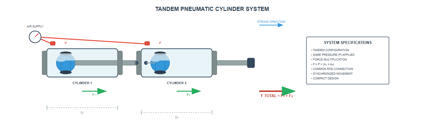
When applications demand higher forces without increasing bore diameter, tandem cylinders provide the solution. These consist of two or more cylinders arranged in series, effectively multiplying the force output while maintaining system pressure limitations.
The hydraulic cylinder offers numerous advantages that make it indispensable in industrial applications. These actuators provide exceptional force density, meaning they can generate enormous forces from relatively compact packages.
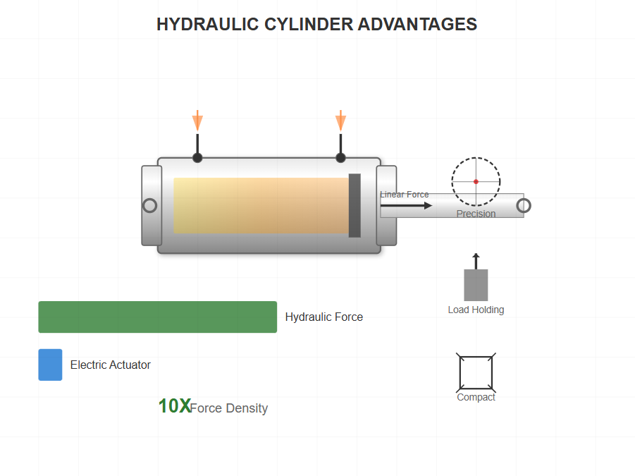
Hydraulic cylinders can generate up to 10 times the force of comparable electric actuators in the same installation space.
"The hydraulic cylinder's ability to multiply force through fluid power has transformed industrial capabilities, enabling feats of engineering that would be impossible with mechanical systems alone."
Understanding the fundamental calculations behind hydraulic cylinder performance is critical for proper system design and component selection.
The fundamental relationship governing hydraulic cylinder performance is the force-pressure-area equation:
Apiston = π × (dbore/2)2
Where:
Fextend = Extending force (N)
P = Pressure (Pa)
Apiston = Piston area (m2)
Arod = π × (drod/2)2
Where:
Fretract = Retracting force (N)
P = Pressure (Pa)
Arod = Rod cross-sectional area (m2)
Consider a hydraulic cylinder with a 100mm bore diameter operating at 200 bar pressure. The piston area calculates to approximately 78.5 square centimeters, yielding an extending force of 157,000 Newtons or roughly 16 tons.
If the rod diameter measures 50mm, the effective retracting area reduces to 58.9 square centimeters, producing a retraction force of approximately 12 tons at the same pressure.
The velocity of a hydraulic cylinder depends directly on the flow rate of hydraulic fluid entering the cylinder and the piston area. The relationship is expressed as:
For applications requiring rapid movement, increasing flow rate provides the solution, though practical limitations exist. Excessive velocities can cause cavitation, seal damage, and hydraulic shock.
Most industrial applications operate cylinders at speeds between 0.1 and 0.5 meters per second, balancing productivity with component longevity.
Relationship between flow rate (LPM) and cylinder speed (m/s) for a 100mm bore cylinder
When hydraulic cylinders operate in compression, particularly with long stroke lengths, buckling becomes a critical design consideration. The Euler buckling formula determines the critical load at which a slender column becomes unstable. For hydraulic cylinders, this analysis must consider the extended rod length, mounting configuration, and safety factors.
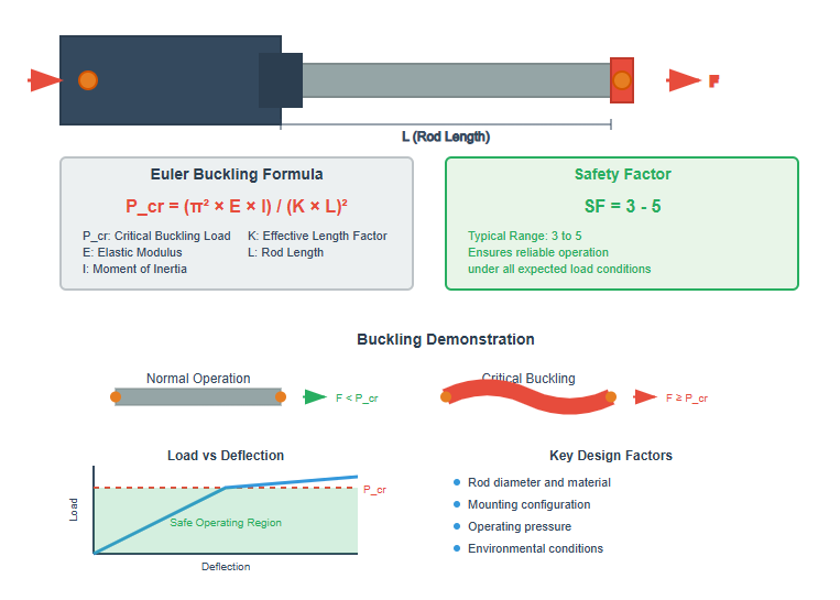
Pcr: Critical buckling load
E: Modulus of elasticity
I: Moment of inertia
K: Effective length factor
L: Length of the rod
Engineers typically apply safety factors between 3 and 5 to ensure reliable operation under all anticipated loading conditions.
K = 0.5
Maximum buckling resistance
K = 0.7
High buckling resistance
K = 1.0
Moderate resistance
K = 2.0
Lowest resistance
A detailed look at the components, sealing systems, and mounting configurations that make hydraulic cylinders work effectively.
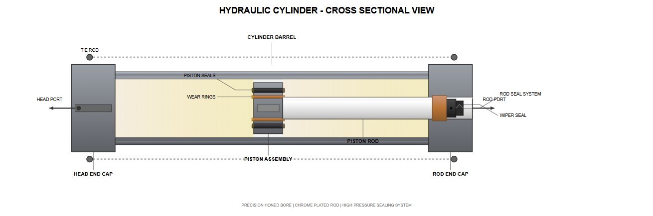
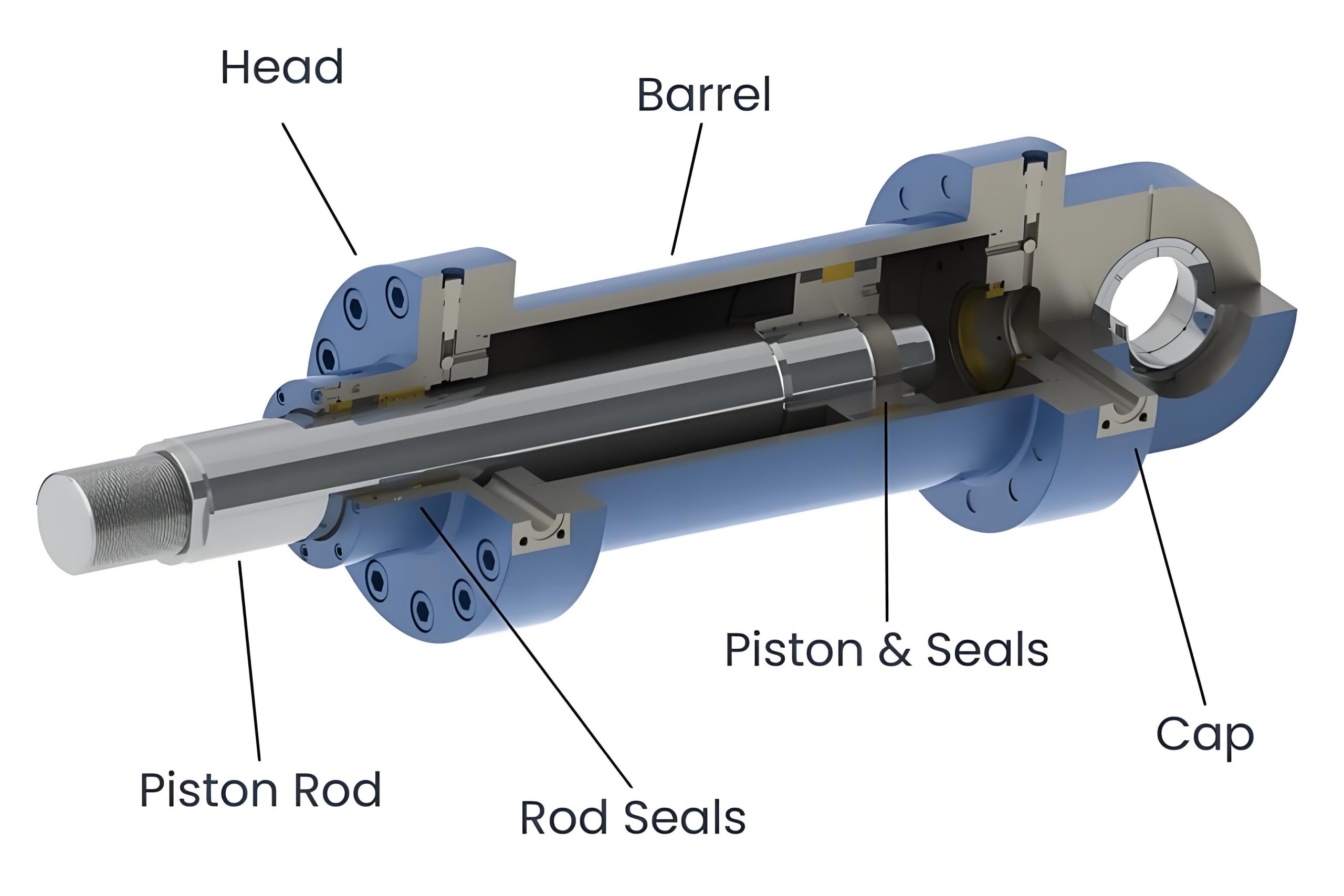
The cylinder barrel forms the main body, precisely honed to provide a smooth sealing surface for the piston. Material selection typically involves high-strength steel or aluminum alloys, depending on pressure requirements and weight constraints.
The piston assembly consists of the piston head, seals, and wear rings. Modern piston designs incorporate multiple sealing elements to prevent internal leakage while minimizing friction. Bronze or polymer wear rings guide the piston while preventing metal-to-metal contact with the cylinder bore.
The rod assembly includes the piston rod, rod seals, wipers, and guide bushings. Chrome-plated or nitride-treated rod surfaces resist corrosion and wear while providing optimal sealing characteristics. The rod seal package prevents external leakage while wipers exclude contaminants from entering the cylinder.
End caps close the ends of the cylinder barrel and contain the fluid ports that direct hydraulic fluid into and out of the cylinder chambers. They are typically fastened with tie rods, bolts, or threaded connections, depending on the cylinder design and pressure rating.
Effective sealing is paramount for hydraulic cylinder performance and longevity. Modern sealing systems employ multiple elements working in concert to prevent leakage while minimizing friction and wear.
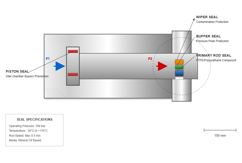
Typically polyurethane or PTFE-based compounds, providing the main barrier against external leakage while maintaining low friction.
Protect primary seals from pressure spikes and system shock, extending service life in demanding applications.
The first line of defense against contamination, removing debris from the rod surface during retraction to prevent internal damage.
Prevent bypass between the cylinder chambers, maintaining efficiency and positioning accuracy during both extension and retraction.
| Material | Temperature Range | Chemical Resistance | Abrasion Resistance | Common Applications |
|---|---|---|---|---|
| Polyurethane | -40°C to +120°C | Good | Excellent | General industrial, mobile hydraulics |
| Nitrile (NBR) | -30°C to +100°C | Fair | Good | Standard hydraulic systems |
| FKM (Viton) | -20°C to +200°C | Excellent | Good | High temperature applications |
| PTFE | -200°C to +260°C | Excellent | Fair | Chemical processing, high purity |
The mounting configuration significantly influences cylinder performance and longevity. Various hydraulic cylinder parts facilitate different mounting styles, each suited to specific application requirements.
Provide rigid attachment for high-force applications. Flanges can be mounted on the head, cap, or both ends, distributing forces evenly through the mounting surface.
Allow pivoting movement to accommodate angular misalignment. Trunnions are typically located at the cylinder's center of gravity to minimize bending moments.
Enable articulation at both ends, ideal for applications with complex motion paths. They accommodate angular movement while maintaining alignment under load.
Offer simple installation for stationary applications, though they may require additional guidance for side loading resistance. Available in flange or block styles.
Feature protruding lugs with holes for pin attachment, providing moderate pivot capability. Suitable for applications with limited space and moderate misalignment.
Utilize threaded rods extending the length of the cylinder to secure end caps. Easily customizable and commonly used in industrial applications.
A comprehensive approach to hydraulic cylinder design incorporating material science, structural analysis, and application requirements.
The design process for a hydraulic cylinder begins with defining application requirements including force, stroke, speed, and duty cycle. Environmental factors such as temperature extremes, contamination exposure, and corrosive conditions influence material selection and sealing system design.
Define application requirements
Force, stroke, speed, duty cycle, and environmental conditions
Calculate basic parameters
Bore size, rod diameter, flow requirements based on force and speed
Perform structural analysis
Stress calculation, buckling analysis, and safety factor verification
Select materials and components
Barrel, rod, seals, and mounting configurations
Validate with advanced analysis
FEA, CFD, and thermal modeling for optimization
Modern design tools including finite element analysis (FEA) enable engineers to optimize cylinder designs for weight, cost, and performance. Stress analysis identifies potential failure points while thermal modeling predicts temperature effects on seals and clearances.
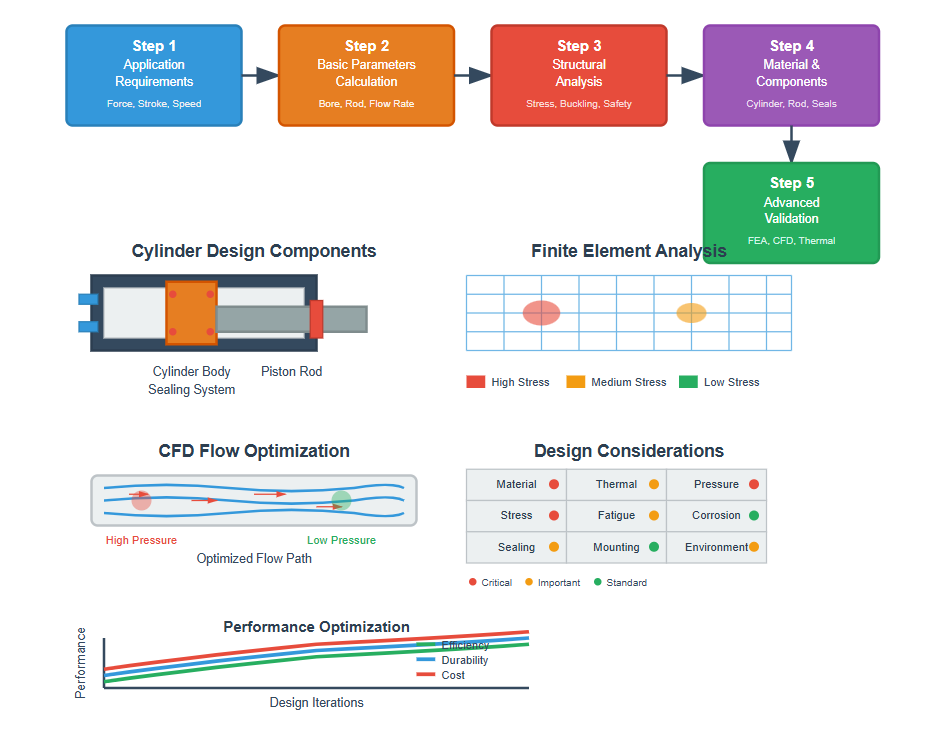
Finite Element Analysis identifies stress concentrations and verifies structural integrity under operating conditions.
Computational Fluid Dynamics optimizes port designs and internal flow paths to minimize pressure losses.
Material selection significantly impacts hydraulic cylinder performance, durability, and cost. The right choices ensure optimal operation under specific application conditions while balancing strength, weight, and corrosion resistance.
Most common material for standard applications, providing excellent strength-to-weight ratio and machinability.
Used for high-pressure applications exceeding 350 bar, providing necessary strength while maintaining acceptable wall thickness.
Selected for weight-sensitive applications where corrosion resistance is important and pressure requirements are moderate.
Base material providing the necessary structural strength for most applications, typically alloy grades like C45 or 4140.
Industry standard surface treatment providing excellent corrosion resistance and wear properties.
Specialized treatments for extreme environments including nickel-chrome plating and ceramic coatings.
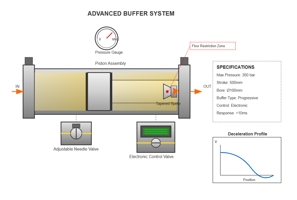
High-speed hydraulic cylinders require cushioning mechanisms to decelerate loads at stroke ends, preventing damage from hydraulic shock. These systems protect both the cylinder and connected equipment from impact damage.
Employs tapered spears or sleeves that progressively restrict fluid flow as the piston approaches the end position, creating controlled deceleration.
Allows optimization for varying loads and speeds through adjustable needle valves that control fluid escape during cushioning.
Provide additional flexibility, enabling electronic control and programmable deceleration profiles for precise motion control.
Proper maintenance ensures optimal hydraulic cylinder performance and longevity. A proactive approach to inspection and troubleshooting can prevent costly downtime and extend component life.
Check rod surfaces for wear, scoring, or corrosion before seal damage occurs. Inspect mounting hardware for tightness and signs of fatigue.
Implement proper filtration, maintain fluid cleanliness standards, and perform regular fluid analysis to prevent contamination-related failures.
Monitor internal leakage through drift tests to reveal seal wear, allowing preventive maintenance before complete failure.
Track operating temperatures to identify abnormal conditions that may indicate internal leakage or insufficient lubrication.
Typically indicates seal wear or rod damage. Inspect rod surface for scoring and replace rod seals if necessary.
Immediate attention requiredSuggests piston seal deterioration. Test by extending cylinder and monitoring for drift under load.
Schedule maintenanceMay result from air entrainment, requiring system bleeding. Check for worn valves or contaminated fluid.
Inspect systemCan be caused by excessive friction from worn components, misalignment, or insufficient fluid flow.
Investigate promptlyHydraulic cylinders serve diverse industries with applications ranging from microscopic positioning systems to massive industrial presses, enabling precise control of powerful linear motion.
Construction equipment relies heavily on hydraulic actuation, with excavators employing multiple cylinders for boom, arm, and bucket control. These applications demand rugged designs and high force capabilities.
Manufacturing applications include injection molding machines, metal forming presses, and automated assembly systems. These require precise control, repeatability, and varying force capacities.
The aerospace industry utilizes specialized hydraulic cylinders for aircraft control surfaces, landing gear actuation, and cargo door operation, demanding exceptional reliability and safety.
Marine applications include ship steering systems, hatch covers, and offshore drilling equipment, requiring corrosion-resistant materials and specialized sealing systems.
Agricultural machinery employs hydraulic cylinders for implement control, steering, and power transmission. The harsh environment demands robust construction.
Mining equipment presents extreme challenges with massive loads, contamination exposure, and continuous operation requirements driving advanced cylinder designs.