
Introduction
In contemporary hydraulic systems, maintaining fluid cleanliness stands as a critical factor determining system reliability, component longevity, and operational efficiency. As any experienced hydraulic equipment supplier will attest, contamination represents one of the primary causes of hydraulic system failure, accounting for approximately 70-80% of all hydraulic component malfunctions.
Filters serve as the essential defensive mechanism against particulate contamination, protecting precision components from premature wear and catastrophic failure. This comprehensive technical analysis examines the fundamental principles, performance characteristics, structural configurations, and application guidelines for hydraulic filters, providing engineers and maintenance professionals with the knowledge necessary to optimize filtration system design and implementation.
Key Contamination Facts
- Contamination causes 70-80% of hydraulic component failures
- Particulate contamination accelerates wear by 3-10 times
- Proper filtration extends component life by 200-400%
- Effective filtration reduces maintenance costs by 40-55%
1. The Critical Role of Filters in Hydraulic Systems
1.1 Contamination Sources and Consequences
Within hydraulic systems, contamination originates from both internal generation and external invasion pathways. Internal sources include component wear particles, oxidation products, seal deterioration fragments, and metal debris from manufacturing processes.
External contaminants enter through breather caps, cylinder rod seals, reservoir openings, and during maintenance operations. According to research published in the International Journal of Fluid Power, "particulate contamination in hydraulic fluids accelerates component wear rates by factors ranging from 3 to 10 times normal wear patterns, with wear rate increases proportional to both particle concentration and hardness characteristics" (Totten, G.E., et al., "Handbook of Hydraulic Fluid Technology," CRC Press, www.crcpress.com).
Any reputable hydraulic equipment supplier understands that these contaminant particles, regardless of their origin, create multiple failure mechanisms. Particles accelerate the wear of precision hydraulic components through abrasive action on bearing surfaces, spool lands, and sealing interfaces. Contamination blocks small orifices in control valves, restricting flow and disrupting system control characteristics. Particles jam valve spools in partially open positions, preventing proper valve operation and creating erratic system behavior. Sharp-edged particles score and cut sealing elements, creating leakage paths and reducing volumetric efficiency. The cumulative effect of these mechanisms leads to valve malfunction, system performance degradation, and ultimately complete system failure.
1.2 Filtration as the Primary Defense Strategy
Modern hydraulic equipment suppliers recognize that controlling hydraulic fluid cleanliness represents the most effective method for preventing contamination-related failures. While multiple contamination control strategies exist, including proper system sealing, effective reservoir design, and careful fluid handling procedures, filtration provides the active mechanism for continuously removing contaminant particles from circulating hydraulic fluid.
"The primary function of hydraulic filters consists of removing particulate matter from hydraulic fluid, maintaining oil cleanliness at levels appropriate for system requirements."
Statistical analysis from industrial maintenance databases indicates that properly designed and maintained filtration systems can:
200-400%
Longer component life
60-75%
Less unscheduled downtime
40-55%
Lower maintenance costs
These improvements are compared to systems with inadequate filtration, demonstrating the substantial return on investment possible through proper filter implementation.
2. Performance Specifications and Technical Indicators
2.1 Filtration Efficiency and Beta Rating
The performance characteristics of hydraulic filters are quantified through several critical specifications, with filtration rating representing the primary indicator. However, as any knowledgeable hydraulic equipment supplier will explain, understanding the complete performance profile requires evaluation of multiple parameters including filtration efficiency, flow capacity, pressure drop characteristics, dirt-holding capacity, and structural integrity under operating conditions.
Filtration efficiency, expressed through the Beta ratio (βx), provides the most meaningful performance metric. The Beta ratio is defined as:
βx = Number of particles larger than x micrometers upstream /
Number of particles larger than x micrometers downstream
Number of particles larger than x micrometers downstream
For example, a filter rated at β10 = 75 captures 74 out of every 75 particles larger than 10 micrometers, representing a filtration efficiency of 98.67%. Higher Beta ratios indicate superior filtration performance. Modern high-performance filters achieve Beta ratios exceeding 1000 (99.9% efficiency) at their rated particle size.
Beta Ratio Efficiency Comparison
Efficiency Calculation: (β - 1)/β × 100%
A higher Beta ratio indicates greater filtration efficiency, with modern premium filters achieving ratios exceeding 1000.
2.2 Filtration Rating Classification
Hydraulic equipment suppliers typically classify filters into four distinct categories based on their filtration rating, which specifies the maximum particle size (expressed as average particle diameter d) that the filter removes from hydraulic fluid:
Coarse Filtration: d ≥ 100 micrometers (0.1mm)
These filters provide basic protection against large debris and are typically employed in reservoir return line applications or as pump inlet strainers. Their primary function involves protecting pumps from catastrophic damage due to large particles.
Standard Filtration: d ≥ 10 micrometers (0.01mm)
Standard filters represent the most commonly specified filtration level for general industrial hydraulic systems. They provide adequate protection for components with clearances typical of medium-pressure systems operating below 14 MPa.
Fine Filtration: d ≥ 1 micrometer (0.001mm)
Fine filters are required for high-pressure systems and applications involving servo valves or proportional valves with tight internal clearances. These filters protect sensitive components operating with clearances in the 2-5 micrometer range.
Ultra-Fine Filtration: d ≥ 0.1 micrometers (0.0001mm)
Ultra-fine filters serve specialized applications requiring exceptional cleanliness levels, such as aerospace hydraulics, precision machine tools, and advanced servo systems with clearances below 2 micrometers.
2.3 Filter Selection Based on System Pressure
The selection of appropriate filtration rating correlates directly with system operating pressure, as pressure levels determine component clearances. Experienced hydraulic equipment suppliers provide the following filtration rating recommendations based on system type and pressure:
| System Type | Operating Pressure | Recommended Filtration Rating |
|---|---|---|
| Lubrication Systems | 0-2.5 MPa | 100 micrometers |
| Transmission Systems | ≤14 MPa | 25-50 micrometers |
| Transmission Systems | 14-21 MPa | 25 micrometers |
| Transmission Systems | >21 MPa | 10 micrometers |
| Servo Systems | Any pressure | 5 micrometers |
Fundamental Principle:
The filtration rating should capture particles smaller than one-half the minimum clearance dimension in system components. For systems operating at pressures exceeding 21 MPa, component clearances typically range from 2-5 micrometers, necessitating filtration ratings of 5-10 micrometers to provide adequate protection.
2.4 Flow Capacity Characteristics
The flow capacity of hydraulic filters, expressed as rated flow, represents another critical performance parameter that hydraulic equipment suppliers must carefully consider during system design.
Rated flow defines the maximum flow rate at which the filter operates while maintaining pressure drop below specified limits, typically 0.1-0.35 MPa for clean filter elements.
Q = k × A × (ΔP)^0.5
Where:
Q = volumetric flow rate (L/min)
k = permeability constant
A = effective filtration area (cm²)
ΔP = pressure differential (MPa)
Where:
Q = volumetric flow rate (L/min)
k = permeability constant
A = effective filtration area (cm²)
ΔP = pressure differential (MPa)
2.5 Pressure Drop Analysis
Pressure drop across hydraulic filters represents the differential pressure between inlet and outlet ports when operating at rated flow with a clean filter element.
Typical pressure drop values for clean filter elements range from 0.015 MPa for large tank-mounted return line filters to 0.35 MPa for high-pressure inline filters.
Most industrial filters incorporate bypass valves or differential pressure indicators that activate when pressure drop reaches 2-3 times the clean element value, typically at 0.3-0.7 MPa depending on filter design.
2.6 & 2.7 Dirt-Holding Capacity & Structural Integrity
Dirt-holding capacity quantifies the mass of contaminant a filter element can capture before reaching terminal pressure drop and requiring replacement.
Advanced filter media designs from leading hydraulic equipment suppliers achieve dirt-holding capacities ranging from 50-200 grams per standard element.
Quality hydraulic equipment suppliers specify collapse pressure ratings, typically ranging from 1.0-3.5 MPa differential pressure, ensuring elements withstand surge conditions without failure.
3. Filter Element Construction and Design Configurations
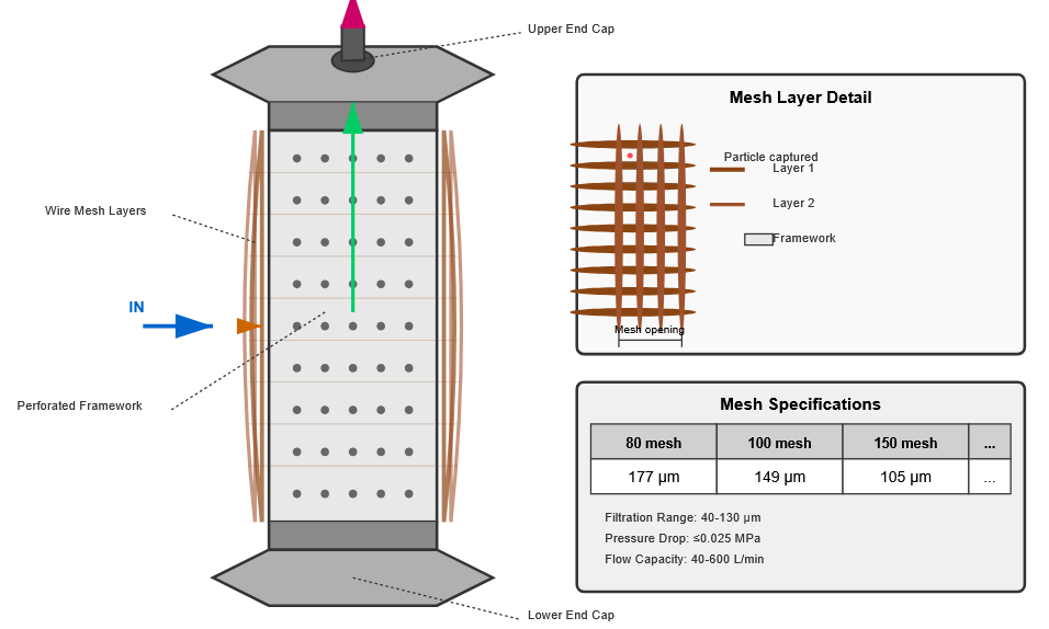
3.1 Wire Mesh Filters
Wire mesh filters, as illustrated in typical construction diagrams, consist of upper and lower end caps connected by a perforated cylindrical plastic or metal framework, with one or multiple layers of woven wire mesh wrapped around the exterior surface.
During operation, hydraulic fluid flows from outside the element, through the wire mesh layers, into the internal cavity, and exits through the upper end cap port. Leading hydraulic equipment suppliers characterize wire mesh filters as coarse filtration devices with ratings of 40-130 micrometers, pressure drops not exceeding 0.025 MPa at rated flow, and flow capacities ranging from 40-600 L/min depending on element dimensions.
Advantages
- Simple construction
- High flow capacity
- Low pressure drop
- Easy to clean and reuse
Limitations
- Relatively coarse filtration
- Vulnerable to pressure surges
- Limited particle capture range
Common Specifications
80-mesh
177 μm
100-mesh
149 μm
150-mesh
105 μm
200-mesh
74 μm
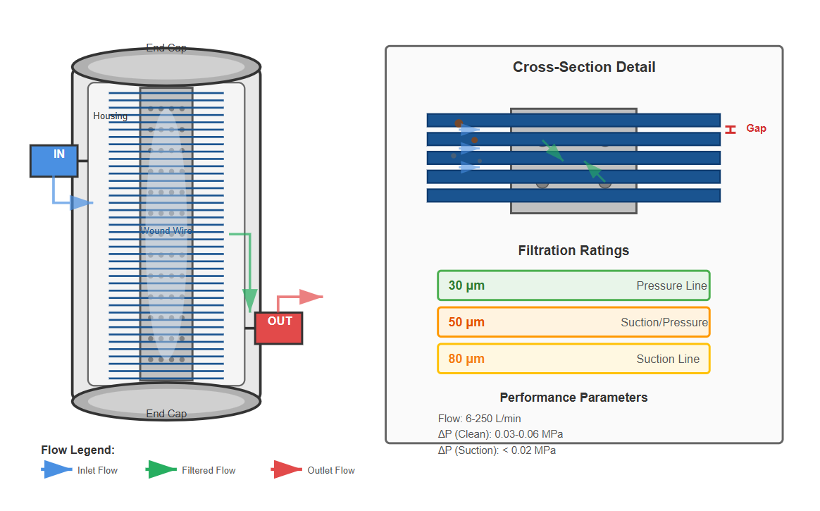
3.2 Gap-Type Wound Wire Filters
Gap-type wound wire filters, constructed from precision wire wound around a perforated cylindrical support core, represent an evolutionary advancement from mesh filters. The filter assembly consists of end caps, housing, perforated tubular framework, and precision-wound metal wire wrapped around the framework exterior.
During operation, fluid enters through the housing inlet port, flows through the gaps between adjacent wire wraps, passes through perforations in the support core, enters the internal cavity, and exits through the outlet port.
This filter type utilizes the precisely controlled gaps between wound wire wraps as the filtration mechanism. Filtration rating depends directly on the gap spacing between adjacent wraps. Standard hydraulic equipment suppliers offer gap-type filters in three filtration ratings: 30 micrometers, 50 micrometers, and 80 micrometers.
Application Categories
Suction Line Filters
- • 50-100 μm filtration
- • Pressure drop < 0.02 MPa
- • Prevent pump cavitation
Pressure Line Filters
- • 30-80 μm filtration
- • Pressure drop < 0.06 MPa
- • For system pressure lines
Rated flow capacities range from 6-250 L/min, with pressure drops of 0.03-0.06 MPa at rated flow for clean elements. Knowledgeable hydraulic equipment suppliers appreciate the advantages of gap-type filters, including simple construction, good flow characteristics, moderate filtration ratings, and widespread application.
3.3 Paper Element Filters
Paper element filters utilize specially treated cellulose fiber media as the filtration material. The construction involves wrapping 0.35-0.45mm thick plain or corrugated resin-impregnated or wood pulp-based microporous filter paper around a perforated core or leather framework.
Fluid flows from the element exterior, through the paper media micropores, into the internal cavity, and exits through the center channel. To maximize filtration surface area within compact dimensions, paper elements typically incorporate pleated or accordion-folded configurations, increasing effective area by factors of 10-15 compared to smooth cylindrical elements of equivalent diameter.
Performance Characteristics
- Filtration ratings: 10 μm and 20 μm
- Pressure drop: 0.01-0.04 MPa
- Media thickness: 0.35-0.45mm
- Surface area increase: 10-15× with pleating
Primary Applications
- Precision filtration requirements
- Return line filtration systems
- Medium-pressure hydraulic circuits
- Cost-sensitive applications
The primary advantage of paper element filters lies in their fine filtration capability and cost-effectiveness. However, significant limitations include inability to clean and reuse elements, requiring periodic replacement, and limited structural strength restricting applications to systems with stable pressure conditions and minimal shock loading.
3.4 Sintered Metal Filters
Sintered metal filters, representing advanced filtration technology, consist of end caps, housing, and sintered metal elements manufactured from spherical metal powder particles, typically bronze or stainless steel.
The sintering process involves heating compacted metal powder to temperatures below the melting point, causing particle-to-particle bonding through solid-state diffusion.
Key Specifications
Filtration Ratings:
1-10 micrometers
Pressure Drop:
0.03-0.2 MPa
Element Thickness:
1.5-6.0mm
Max Pressure:
Exceeding 35 MPa
Sintered metal filters provide numerous advantages including high structural strength enabling use in pressures exceeding 35 MPa, capability for forming complex geometries, excellent filtration efficiency, and superior dirt-holding capacity. These characteristics make sintered elements the preferred choice for high-pressure applications and servo systems.
3.5 Synthetic Fiber Media Filters
Modern synthetic fiber filter elements, developed over the past two decades, utilize advanced polymeric microfibers with diameters ranging from 0.5-3.0 micrometers arranged in multi-layered gradient density structures.
These media combine depth filtration and surface filtration mechanisms, capturing particles throughout the media thickness rather than solely on the surface. Progressive hydraulic equipment suppliers increasingly specify synthetic media for their superior dirt-holding capacity (150-250% greater than cellulose), lower pressure drop (30-40% reduction compared to equivalent paper media), and extended service life.
Performance Advantages
- 150-250% greater dirt-holding capacity
- 30-40% lower pressure drop
- 2-4 times longer service life
- Wide temperature range: -40°C to +135°C
Filtration ratings for synthetic media range from 1-25 micrometers with Beta ratios exceeding 1000 at rated particle size. These elements demonstrate excellent chemical compatibility with synthetic and petroleum-based hydraulic fluids, and exhibit structural integrity at differential pressures exceeding 2.0 MPa.
4. Engineering Guidelines for Filter Selection
Selecting appropriate hydraulic filters requires comprehensive analysis integrating system technical requirements with filter performance characteristics. Experienced hydraulic equipment suppliers emphasize that filter selection represents a multi-variable optimization problem balancing filtration efficiency, pressure drop, dirt-holding capacity, structural integrity, and cost constraints.
4.1 System Pressure
System operating pressure constitutes the primary factor determining required filtration rating. Pressure levels directly correlate with component internal clearances.
- High pressure (35 MPa): 3-5 μm filtration
- Medium pressure (16 MPa): 10-15 μm filtration
- Clearances: 5-8 μm for high-pressure pumps
- Clearances: 15-25 μm for gear pumps
4.2 Flow Capacity
Flow capacity represents the second critical selection parameter. Filter rated flow must equal or exceed system maximum flow.
- General applications: 110-150% of nominal flow
- Variable flow systems: 125-175% of nominal flow
- Critical applications: 150-200% of nominal flow
- Oversizing avoids premature plugging
4.3 Structural Strength
Element structural strength becomes critical in high-pressure systems and applications experiencing pressure surges or cold start conditions.
- Low pressure (<10 MPa): 0.5-1.0 MPa collapse
- Medium pressure (10-21 MPa): 1.0-2.0 MPa
- High pressure (>21 MPa): 2.0-3.5 MPa+
- Sintered metal excels in high-pressure apps
4.4 Media Selection
Media selection balances filtration efficiency, dirt-holding capacity, chemical compatibility, temperature range, and cost.
- Cellulose: Cost-effective general use
- Synthetic: Extended service intervals
- Wire mesh: Coarse filtration, reusable
- Sintered metal: High-pressure applications
Media Selection Matrix
Leading hydraulic equipment suppliers offer comprehensive media selection matrices integrating key parameters to guide optimal filter media choice for specific application requirements:
| Media Type | Filtration Range (μm) | Temperature Range (°C) | Max Pressure (MPa) | Best Applications |
|---|---|---|---|---|
| Cellulose | 5-25 | -10 to +90 | 1.0 | General industrial, petroleum fluids, cost-sensitive |
| Synthetic | 1-25 | -40 to +135 | 2.0 | Extended service, synthetic fluids, wide temperature |
| Wire Mesh | 40-150 | -20 to +120 | 1.0 | Pump suction, coarse prefiltration, reusable needs |
| Sintered Metal | 1-10 | -20 to +150 | 35+ | High-pressure, servo systems, extreme conditions |
5. Strategic Filter Installation Configurations
Strategic filter placement within hydraulic circuits significantly influences overall system protection effectiveness and operational efficiency. Knowledgeable hydraulic equipment suppliers recognize five primary installation configurations, each offering distinct advantages and limitations.
5.1 Pump Suction Line Installation
Protects pump from large contaminants
Prevents reservoir contamination entering pump
Limited to coarse filtration
75-150μm to avoid cavitation
No protection from pump-generated contaminants
Wear particles circulate through system
Key Specifications
- • Pressure drop must be < 0.025 MPa
- • Filtration rating: 75-150 micrometers
- • Typically wire mesh construction
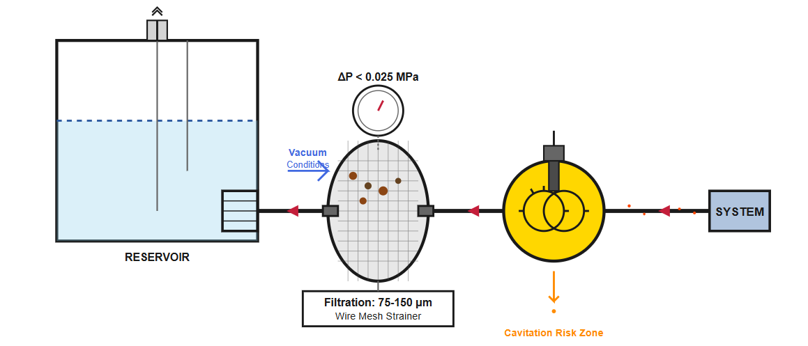
Pump suction line installation, positioning the filter between the reservoir and pump inlet, provides protection for all system components by preventing reservoir contamination from entering the pump. However, the vacuum conditions present in suction lines impose severe restrictions on filter selection.
Pressure drop must remain below 0.02-0.025 MPa to prevent pump cavitation, effectively limiting selection to coarse wire mesh strainers with ratings of 75-150 micrometers. These coarse elements fail to protect against wear particles generated by the pump itself, which become distributed throughout the system.
Consequently, suction line filtration alone provides inadequate protection for precision components, requiring supplementary filtration elsewhere in the circuit. Experienced hydraulic equipment suppliers typically specify suction strainers as a first-stage protection level in multi-stage filtration strategies, rather than as comprehensive system filtration.
5.2 Pump Discharge Pressure Line Installation
Protects all downstream components
Captures pump wear debris before distribution
Prevents system-wide contamination
Stops new contaminants at source
Operates at maximum system pressure
Requires high structural integrity
Key Specifications
- • Must withstand full system pressure
- • Incorporates bypass valve (0.5-0.7 MPa)
- • Differential pressure indicators recommended
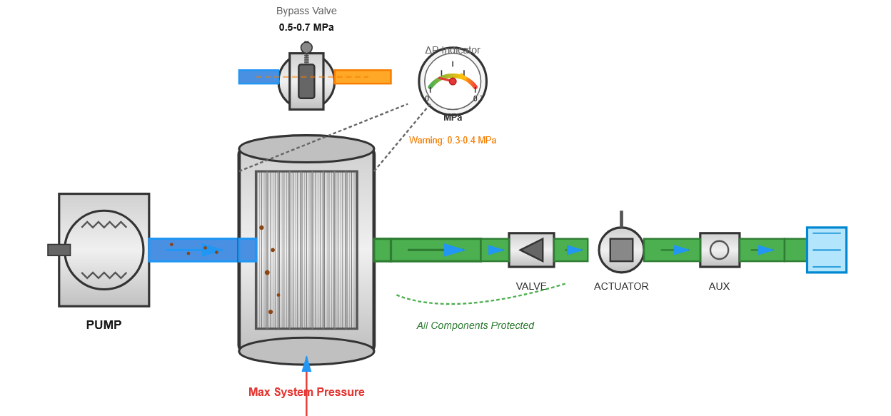
Pump discharge pressure line installation locates filters immediately downstream of the pump, providing comprehensive protection for all downstream components including valves, actuators, and auxiliary equipment. This configuration effectively captures pump wear debris before distribution throughout the system.
However, filters in this location operate continuously at maximum system pressure, requiring elements with superior structural integrity to withstand pressure surges and potential shock loading. Pressure drop across the filter directly reduces system available pressure, potentially limiting actuator force or speed capabilities.
To protect against filter element failure or excessive pressure drop due to contamination accumulation, professional hydraulic equipment suppliers install bypass valves or differential pressure indicators in pressure line filters. Bypass valves typically open at 0.5-0.7 MPa differential pressure, routing unfiltered fluid around the element to prevent pump overload or element collapse.
Differential pressure indicators provide visual or electrical signals when pressure drop reaches warning thresholds, typically at 0.3-0.4 MPa, enabling proactive element maintenance before bypass activation.
5.3 Return Line Installation
Return line installation positions filters in the drain line returning fluid from system components to the reservoir. This configuration captures contaminant generated throughout the system.
Return line pressures typically remain low (0.2-0.5 MPa), eliminating high structural strength requirements and permitting selection of economical filter elements.
Primary Benefits
- Captures wear particles from all components
- Low pressure allows finer filtration
- Cost-effective protection strategy
- Pressure drop minimally impacts system
5.4 Branch Circuit Installation
Branch circuit installation locates filters in specific circuit sections requiring enhanced protection, most commonly in relief valve drain lines or servo valve supply lines.
Installing filters in relief valve drain circuits captures contaminant generated by high-velocity flow across valve seats during pressure limiting operations.
Primary Applications
- Servo valve supply lines (3-5μm filtration)
- Relief valve drain circuits
- Precision control valve circuits
- High-sensitivity measurement circuits
5.5 Offline Kidney Loop Filtration
Offline kidney loop filtration employs a dedicated pump and filter assembly operating independently from the main hydraulic system, continuously circulating reservoir fluid through fine filtration.
Kidney loop flow rates typically equal 5-10% of main system pump flow, achieving complete reservoir volume filtration every 20-30 minutes during machine operation.
Key Advantages
- No impact on main circuit pressure drop
- Continuous purification during idle periods
- Can include fluid conditioning equipment
- Easy to upgrade without system modification
Summary of Key Findings
Effective hydraulic filtration represents a critical investment in system reliability, with properly designed filtration systems capable of extending component life by 200-400% while reducing maintenance costs by 40-55%. The selection process requires careful consideration of multiple interrelated factors including system pressure, flow requirements, contamination sources, and component sensitivity.
Modern filter technologies, particularly synthetic media and sintered metal designs, offer significant performance advantages over traditional materials, providing superior dirt-holding capacity, extended service intervals, and improved filtration efficiency. Strategic filter placement, whether in pressure lines, return lines, or dedicated kidney loop systems, further enhances protection while minimizing pressure drop penalties.
Best Practices for Optimal Filtration
- Select filtration rating based on component clearances (typically half the minimum clearance)
- Size filters for 110-150% of nominal flow to extend service life
- Utilize multi-stage filtration strategies combining suction and return line filters
- Implement kidney loop systems for large reservoirs or critical applications
- Monitor pressure drop indicators to schedule proactive maintenance