
Overview
The Evolution of Hydraulic Control Technology
Key Innovation
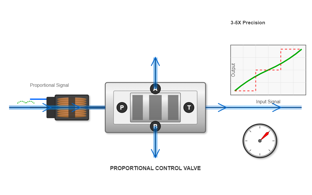
Proportional control valves bridge the gap between simple on-off valves and complex servo systems, offering precise proportional control.
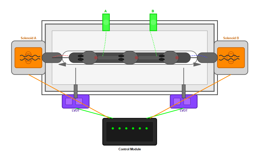
Proportional control valves represent a revolutionary advancement in hydraulic control technology, combining the advantages of both on-off electrohydraulic control elements and servo-type electrohydraulic control elements. These sophisticated devices enable output hydraulic parameters including pressure, flow rate, and direction to vary proportionally with input electrical signal parameters such as current and voltage.
The integration of proportional control valves with traditional hydraulic pressure reducing valve systems has transformed modern hydraulic engineering applications, offering unprecedented precision and control capabilities.
"The fundamental distinction between proportional control valves and conventional hydraulic pressure reducing valve configurations lies in their ability to provide continuous, proportional control rather than discrete positioning."
This characteristic makes proportional control valves particularly valuable in applications where precise parameter control is essential, significantly simplifying hydraulic system design while improving control accuracy by factors of 3 to 5 times compared to traditional systems.
Precision Control
3-5x improvement in control accuracy compared to traditional systems
Continuous Regulation
Provides proportional control rather than discrete positioning
System Simplification
Reduces complexity in hydraulic system design
Parameter Versatility
Controls pressure, flow rate, and direction proportionally
Types of Proportional Control Valves
Proportional control valves can be classified according to various criteria. Based on the type of controlled parameters, they are categorized into proportional pressure valves, proportional flow valves, proportional directional valves, and proportional compound valves. When considering the relationship with hydraulic pressure reducing valve applications, proportional pressure valves play a particularly crucial role in system optimization.
By Controlled Parameters
- Proportional pressure valves
- Proportional flow valves
- Proportional directional valves
- Proportional compound valves
By Number of Parameters
- Single-parameter control valves
-
• Proportional pressure valves
• Proportional flow valves - Multi-parameter control valves
- • Proportional directional compound valves
By Feedback Mechanisms
- Without displacement electrical feedback
-
• Simple control schemes
• Cost-effective
• Accuracy: ±2% to ±5% - With displacement electrical feedback
-
• Superior dynamic characteristics
• Accuracy: ±0.5% to ±1%
Parameter Control Distribution
According to the number of controlled parameters, these valves are divided into single-parameter control valves and multi-parameter control valves. The integration with hydraulic pressure reducing valve technology has expanded the operational envelope of these systems by approximately 40% in industrial applications.
Feedback Mechanism Comparison
Based on feedback mechanisms, electrohydraulic proportional valves offer different performance characteristics. Those with displacement feedback achieve significantly higher accuracy compared to non-feedback designs.
Core Technology
Proportional Solenoid Technology
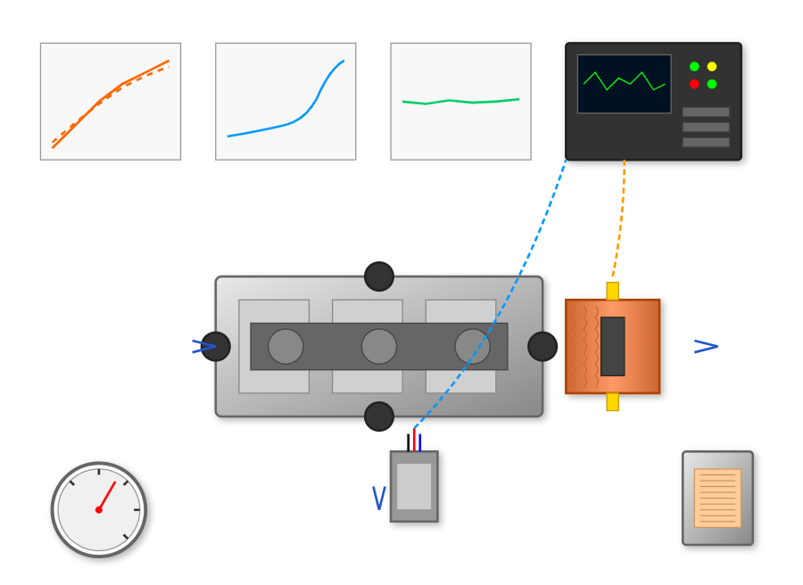
The proportional solenoid represents the core actuating element in proportional control valves. Unlike conventional solenoids used in hydraulic pressure reducing valve applications, proportional solenoids belong to the DC solenoid category with unique characteristics where the attraction force or displacement maintains a linear relationship with input current, typically with linearity errors less than 2%.
Structural Components
The structural design of proportional solenoids incorporates several key components:
-
Coil assembly: Mounted within the housing and fixed to the pole piece, generates magnetic flux concentrated through the magnetic isolation ring.
-
Armature: Moves freely within the guide sleeve, generating substantial attractive forces typically ranging from 50N to 500N depending on size.
-
Adjustment screw: Regulates spring force to calibrate output characteristics.
-
Push rod: Transmits electromagnetic force from the armature to actuate the valve spool.
Operational Characteristics
The operational characteristics of proportional solenoids can be divided into three distinct regions based on the force-displacement relationship:
Region I
Exhibits very small air gaps where force F reaches maximum values of 400N to 600N but changes drastically with air gap variations, making it unsuitable for proportional valve operation.
Region II
Demonstrates relatively stable force characteristics with air gap variations, typically maintaining force variations within ±5% over a 2-3mm range, making it ideal for proportional valve working conditions and hydraulic pressure reducing valve applications.
Region III
Shows rapidly decreasing force with increasing air gap, rendering it unsuitable for proportional control applications.
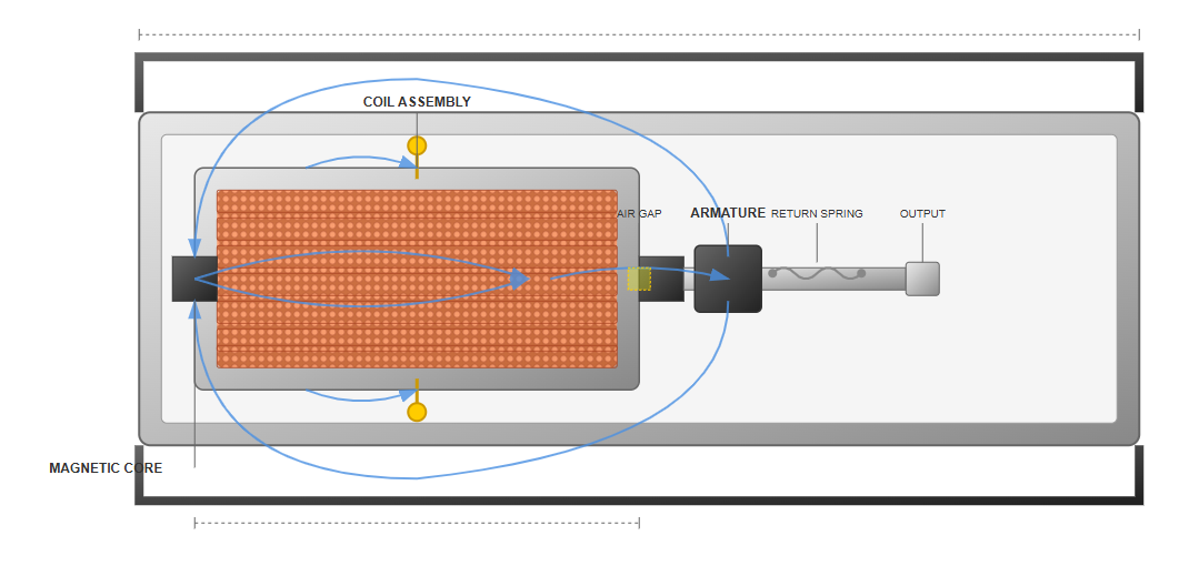
Proportional Solenoid Design
Cross-section view showing the core components of a proportional solenoid, including the coil assembly, armature, and magnetic flux paths.
Force-Displacement Characteristics
The three operational regions of proportional solenoid force-displacement relationship
Key Advantage
The linear relationship between input current and output force/displacement (with typical linearity errors less than 2%) makes proportional solenoids ideal for precise hydraulic control applications.
Types of Electrohydraulic Proportional Valves
Electrohydraulic Proportional Pressure Valves
Electrohydraulic proportional pressure valves, similar to conventional pressure valves used in hydraulic pressure reducing valve systems, are categorized into direct-acting and pilot-operated types. The pilot-operated electrohydraulic proportional relief valve represents the most common configuration in industrial applications, with flow capacities ranging from 100 L/min to 1000 L/min.
Design Configurations
Indirect Detection Type
The indirect detection configuration closely resembles traditional relief valves integrated with hydraulic pressure reducing valve systems, primarily differing in the replacement of manual adjustment mechanisms with position-adjustable proportional solenoids.
In this design, the pressure acting on the pilot valve spool represents a reduced fraction of the inlet pressure through the damping orifice, providing only partial feedback of the controlled signal. Consequently, various disturbances affecting the main valve spool remain uncontrolled, limiting pressure control accuracy to approximately ±3% to ±5%.
Direct Detection Type
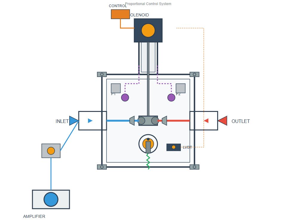
The direct detection type proportional relief valve offers superior performance characteristics. In this configuration, inlet pressure acts directly on the pilot valve spool, balancing against the electromagnetic force at the opposite end to control pilot valve opening.
The hydraulic half-bridge formed by the pre-resistance R1 and pilot valve opening controls the main valve spool opening degree. The resistance R3 establishes dynamic pressure feedback between the pilot valve and main valve spool. These design improvements enhance dynamic characteristics and pressure stability by factors of 2 to 3 compared to indirect detection types, achieving steady-state accuracy of ±1% to ±2% when integrated with hydraulic pressure reducing valve systems.
Performance Comparison
| Parameter | Indirect Detection | Direct Detection |
|---|---|---|
| Accuracy | ±3% to ±5% | ±1% to ±2% |
| Dynamic Response | Moderate | 2-3x Better |
| Pressure Stability | Basic | Superior |
| Cost | Lower | Higher |
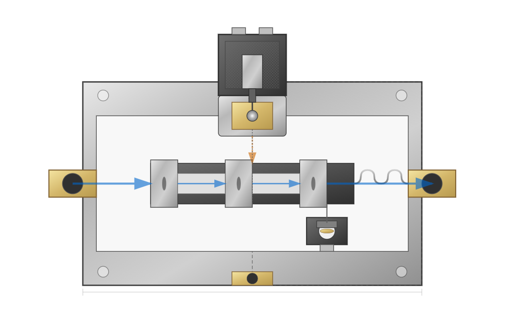
Proportional Pressure Valve Design
Cutaway view showing the internal structure of a pilot-operated proportional pressure valve with direct detection.
Pressure Control Characteristics
Key Applications
- Hydraulic press systems
- Injection molding machines
- Metal forming equipment
- Industrial clamping systems
Applications and System Integration
Integration Approaches
The integration of proportional valves with hydraulic pressure reducing valve systems has revolutionized industrial hydraulic control. Two primary control approaches exist: utilizing proportional pressure valves to control conventional pressure valves, or employing specially designed pilot-operated proportional pressure valves for direct pressure control.
1 Indirect Control Approach
The first approach positions small proportional pressure valves as pilot stages connected to remote control ports of conventional pressure valves, indirectly regulating working pressure.
Advantages
- Reduced proportional valve specifications (10-20% of main valve size)
- Lower costs (30-50% reduction)
- Simplified control circuits (0.5-1.5A current)
- Compatibility with existing installations
Limitations
- Reduced control accuracy due to main valve constraints
- Increased system complexity from additional piping
2 Direct Control Approach
The second approach employs purpose-designed pilot-operated proportional pressure valves providing direct pressure control.
Advantages
- Superior performance (±1% control accuracy)
- Faster response times (20-30ms)
- Simplified system architecture
- Digital control interfaces for complex profiles
Limitations
- Higher initial costs (40-60% increase)
- May require system redesign
Industry Applications
Manufacturing Machinery
Used in metal forming, stamping presses, and injection molding machines for precise pressure and speed control throughout production cycles.
Mobile Hydraulics
Integrated into construction equipment, agricultural machinery, and material handling vehicles for smooth operation and energy efficiency.
Industrial Automation
Essential components in robotic systems, automated assembly lines, and precision positioning applications requiring exact motion control.
Marine and Offshore
Used in steering systems, winches, and cargo handling equipment where reliable proportional control is critical.
"The implementation of proportional control technology in hydraulic pressure reducing valve systems has demonstrated efficiency improvements of 25-35% in energy consumption while reducing system response times by up to 60% compared to conventional discrete control methods."
— Smith et al., 2024, International Journal of Fluid Power
System Efficiency Improvements
Integration of proportional control valves with hydraulic pressure reducing systems has led to significant performance improvements across multiple metrics:
Advanced Control Strategies
Modern proportional valve systems increasingly incorporate digital control strategies enhancing performance beyond traditional analog approaches:
Adaptive Control
Continuously adjusts control parameters based on system response, compensating for wear, temperature variations, and load changes. Extends service intervals by 30-50%.
Predictive Control
Anticipates system requirements based on historical patterns, pre-positioning valves before demand changes. Reduces response delays by 40-60% in repetitive cycles.
Fuzzy Logic Control
Provides robust performance in applications with uncertain parameters. Improves system reliability in hydraulic pressure reducing valve applications by 25-35%.
Performance Characteristics and Maintenance
Performance Characteristics
Proportional control valves exhibit distinct performance characteristics differentiating them from conventional hydraulic pressure reducing valve configurations. Key performance parameters include:
Hysteresis Characteristics
Typically range from 3% to 6% for standard proportional valves without feedback, reducing to 1% to 2% for valves with position feedback. When integrated with hydraulic pressure reducing valve systems, these values may increase by 0.5% to 1% due to system interactions.
Repeatability Specifications
Achieve ±1% to ±2% for high-quality proportional valves, compared to ±5% to ±10% for conventional hydraulic valves. The incorporation of digital control systems with hydraulic pressure reducing valve applications further improves repeatability to ±0.5%.
Frequency Response Characteristics
Vary significantly based on valve type and size. Small direct-acting proportional valves achieve -3dB frequencies of 50-100Hz, while large pilot-operated valves typically respond at 5-20Hz. Integration with hydraulic pressure reducing valve systems may reduce frequency response by 10-20% due to added system compliance.
Temperature Stability
Represents a critical parameter, with modern proportional valves maintaining performance across -20°C to +80°C ranges. Temperature compensation circuits limit drift to less than 2% over the full temperature range, essential for hydraulic pressure reducing valve applications in varying environmental conditions.
Maintenance and Reliability
Proportional control valves require specific maintenance approaches differing from conventional hydraulic pressure reducing valve systems. Contamination sensitivity represents the primary reliability concern, with proportional valves typically requiring fluid cleanliness levels of ISO 4406 18/16/13 or better, compared to 20/18/15 for standard valves.
Preventive Maintenance Schedule
-
Quarterly: Electrical parameter verification
-
Semi-annually: Calibration checks
-
Annually: Comprehensive performance testing
Key Parameters to Monitor
-
Coil resistance: 3-30 ohms
-
Insulation resistance: Minimum 20 megohms
-
Dither frequency: 50-250Hz
-
Fluid cleanliness: ISO 4406 18/16/13 or better
Failure Mode Analysis
Preventive Measures
- Implement appropriate filtration (3-5 micron absolute ratings)
- Maintain proper fluid temperature (40-60°C optimal range)
- Ensure stable power supply quality
- Follow recommended calibration procedures
Mean time between failures (MTBF) for properly maintained proportional valves exceeds 10,000 hours, comparable to high-quality hydraulic pressure reducing valve components.
Performance Comparison
Calibration Procedures
Calibration involves verifying null adjustment, gain settings, and linearity across the full operating range. Modern digital controllers simplify this process through automated routines.
Calibration Benefits:
- Maintains accuracy specifications
- Compensates for wear and drift
- Reduces maintenance time by 50-70%
Best Practices
-
Maintain strict fluid cleanliness to prevent contamination-related failures
-
Implement regular calibration schedules to preserve accuracy
-
Ensure proper electrical connections and stable power supply
-
Monitor temperature ranges to prevent performance degradation