
Low hydraulic system pressure usually means oil is bypassing somewhere it shouldn't. The fix normally starts with a dead-head test at the pump outlet, then moves to relief valve inspection, valve-by-valve return line temperature checks, and cylinder seal verification. This sequence reflects the way our technical team approaches pressure-loss diagnosis in the field — starting with isolation, then narrowing the fault path before any major component is replaced.
Two months ago a steel fabrication shop in Pennsylvania called us about a press brake that had gradually lost clamping force over six weeks. Their maintenance crew had already replaced the hydraulic pump — a $3,800 variable-displacement piston unit. Pressure was still 600 PSI below setpoint. Turns out the pump was never the problem. A pilot-operated relief valve had a hairline crack in its pilot piston seat, dumping flow to tank at just under 2,400 PSI instead of the 3,000 PSI spec. Total cost of the actual fix: $220 in parts and two hours of labor.

That story isn't unusual. It plays out in shops and on job sites every week, and it almost always starts the same way — someone assumes the pump is bad because the gauge reads low. The instinct makes sense. The pump makes pressure, right? Actually, no. That misconception is where most troubleshooting goes sideways.
At POZOOM, these calls usually begin the same way: a customer sends the original model or a nameplate photo, explains the machine's operating pressure and flow requirement, and tells us whether they are trying to repair the existing unit or confirm a replacement. That information matters because pressure loss is rarely diagnosed correctly from the gauge reading alone. You need the circuit context, the operating condition, and the component path before the root cause becomes clear.
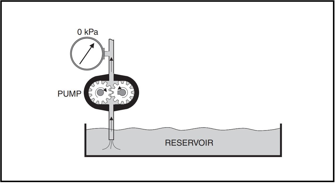
A hydraulic pump creates flow. Pressure is the result of that flow meeting resistance — load on a cylinder, restriction through a valve, or backpressure from a motor. If resistance drops because a seal blows out or a valve spool hangs open, the gauge drops with it. The pump didn't fail. The resistance disappeared.
Understanding this distinction changes how you approach every low-pressure diagnosis. Instead of asking "what's wrong with the pump?" you start asking "where did the resistance go?" That question leads you to the answer faster because it points you toward leaks, bypasses, and misadjusted valves — the actual causes behind most pressure drops.
I can't overstate this. Before disconnecting a single fitting, write down the pressure readings at every gauge point in the circuit — main system pressure, individual circuit pressures, charge pressure if applicable. Note the hydraulic fluid temperature. A system running at 170°F will show different pressures than one at 110°F because viscosity changes with temperature and affects internal leakage rates across every component.
Record what the machine is doing (or not doing) at each pressure reading. "Boom cylinder won't hold load at 2,200 PSI" gives you diagnostic direction. "Pressure is low" gives you nothing.
This single test splits your troubleshooting time in half. Close a manual shutoff valve between the pump/relief section and the rest of the circuit. If your system doesn't have one, you may need to cap a line. With everything downstream blocked off, start the pump.
Three outcomes are possible. If pressure climbs to the relief valve setting and holds, your pump and relief valve are both healthy — the problem lives somewhere downstream in the valves, cylinders, or motors. If pressure stays low, the fault is in the power supply section — either the pump can't generate enough flow or the relief valve is dumping prematurely. If pressure builds slowly but never reaches spec, you may be dealing with a pump that's worn enough to leak internally under load but can still produce flow at low pressure.
That third scenario trips people up. A pump with 20% internal leakage can look fine at low pressure and fall on its face at working pressure. Volumetric efficiency testing with a flow meter — measuring actual output versus theoretical displacement — is the only reliable way to catch it.
When a dead-head test points toward the pump or power unit section, the next step is not always immediate replacement. In many cases, it makes sense to compare the actual machine data against the original technical information first. Our support workflow typically includes checking the model or nameplate, operating pressure, required flow, installation limits, and application environment, then comparing that against available pump or motor options. For customers who need deeper verification, we also provide product manuals, installation guidance, CAD drawings, performance curves, and other technical reference materials that help confirm fit and operating range before parts are ordered.
In practical troubleshooting, a malfunctioning relief valve is one of the first components worth checking before blaming the pump. Contamination is often the trigger. A particle smaller than a human hair can lodge in a pilot orifice and prevent the valve from seating fully. Once that happens, oil shortcuts to tank and system pressure falls below the expected setting.
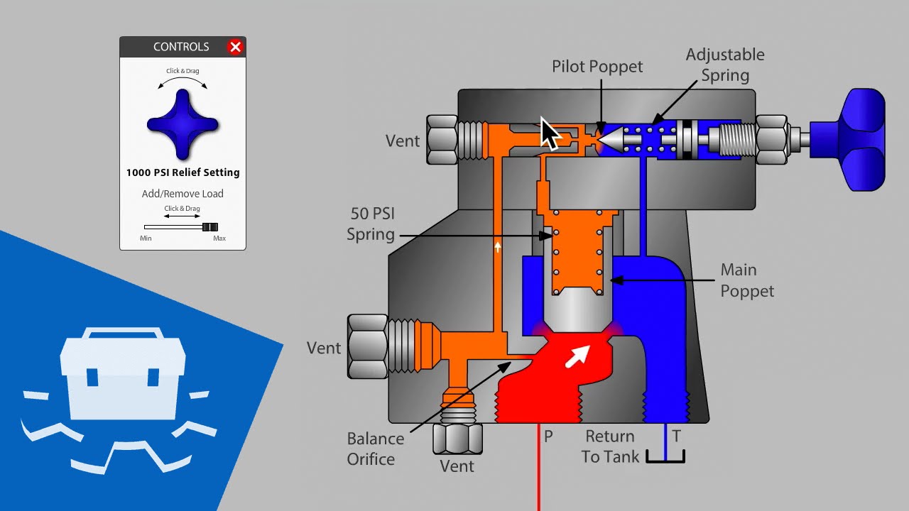
Here's what the check looks like in practice. With the system dead-headed, try adjusting the relief valve upward. If pressure doesn't respond — or if you feel no spring resistance in the adjustment screw — pull the valve. Inspect every orifice, spring, and seating surface. One facility we worked with last year had already pulled and inspected their relief valve twice before calling us. They found two orifices and confirmed both were clear. A third orifice, tucked behind the pilot spool, had a speck of debris no bigger than a grain of sand. Cleaned it, reinstalled the valve, and pressure came right back to 3,000 PSI.
This technique doesn't require any disassembly. Grab an infrared thermometer and scan the return lines coming off each directional control valve in the circuit. Under normal conditions, return lines run warm — maybe 10–20°F above ambient. A return line that's running 40–60°F hotter than its neighbors is carrying flow it shouldn't be. Oil is leaking across that valve's spool internally, taking a shortcut back to tank and robbing pressure from the rest of the system.
Quick-Reference: Common Low-Pressure Culprits Ranked by Frequency
Rod seal leaks announce themselves — you'll see oil on the rod and puddles under the machine. Piston seal leaks are invisible from the outside and account for a surprising number of "mystery" pressure losses. A hydraulic cylinder with blown piston seals acts as a direct path from the high-pressure side to the low-pressure side, robbing the circuit of the resistance it needs to build pressure.
The test is straightforward. Drive the cylinder to full extension or retraction under load. Hold pressure. Disconnect or crack open the line on the non-pressurized port. If oil flows out at any meaningful rate, the piston seals are bypassing. On a healthy cylinder, you'll see zero flow or a few drops at most. I've seen cylinders pass a visual inspection and still bypass 3–4 GPM internally — enough to drop system pressure by 500 PSI on a mid-size circuit.
After ruling out downstream causes, the pump gets its turn on the witness stand. The most reliable field test uses a flow meter installed in the relief valve tank line with the system dead-headed. Back the relief valve adjustment fully counterclockwise to minimize pressure. Start the pump. At near-zero pressure, the pump should deliver close to its theoretical flow rate. Gradually increase relief pressure toward the normal operating point while watching the flow meter.
A healthy pump maintains flow as pressure increases — maybe losing 3–5% to internal clearances. A worn pump bleeds flow progressively. If you lose 15% or more of rated flow by the time you reach operating pressure, the rotating group needs attention. For variable-displacement piston pumps, also check case drain flow. Anything over 5% of pump displacement volume flowing out the case drain indicates worn pistons, shoes, or a damaged valve plate. At that point, you're looking at a rebuild or replacement.
That distinction matters because not every weak pump needs to be treated as a blind swap. In hydraulic maintenance work, failure modes such as rotor wear, cylinder-surface damage, shaft-seal wear, valve-plate damage, and volumetric-efficiency loss should be confirmed before replacement is recommended. Our related repair workflow also includes bench testing and evaluation of pump and motor platforms used in industrial and mobile hydraulic systems, so pressure loss is judged by measured flow, leakage pattern, and test results rather than guesswork.
Most low-pressure events trace back to contamination. Particles wear pump internals, score valve spools, damage cylinder seals, and clog pilot orifices in relief valves. A proactive fluid management program — regular oil sampling, timely filter changes, and breather maintenance — prevents the majority of the failures I've described above.
Fluid temperature control matters equally. Every 18°F (10°C) increase above optimal operating temperature cuts hydraulic oil life roughly in half and reduces viscosity, which accelerates internal leakage across every component in the circuit. A system that runs at 160°F instead of 130°F isn't just running hot — it's aging every seal and wearing every close-tolerance surface faster than it should.
Schedule baseline pressure and flow measurements quarterly. The data doesn't need to be elaborate — a dated entry in a maintenance log with pressure readings at key test points and fluid temperature. When pressure eventually does drop, you'll have a trend line that narrows the search. A gradual decline over months points to wear. A sudden drop points to a discrete failure — a broken spring, a blown seal, a stuck valve.
If you are troubleshooting a recurring pressure-loss issue and need to verify a replacement or compare against the original specification, it helps to gather the model/nameplate photo, pressure and flow requirement, installation constraints, and application details before contacting support. That shortens the diagnosis path and makes it easier to confirm whether the problem points to adjustment, contamination, internal leakage, wear, or a genuine component mismatch.
Oil finding an unintended shortcut back to the reservoir. The most frequent causes are contaminated or misadjusted relief valves, internal valve spool leakage, blown cylinder piston seals, worn pump internals, suction restrictions causing cavitation, and hydraulic fluid that's too hot or too thin to maintain sealing clearances.
Dead-head the system by blocking downstream flow, install a gauge at the pump outlet, and check if pressure reaches the relief setting. If it does, the pump is fine. For a definitive assessment, use a flow meter to measure actual pump output at working pressure versus theoretical displacement. A drop beyond 10–15% under load means the pump needs rebuilding.
Absolutely — and it's the most common cause we see in systems under five years old. Contamination, worn springs, and improper adjustment can all prevent a relief valve from holding its set pressure, allowing oil to bypass back to tank at pressures well below spec.
Stroke the cylinder fully under load, hold pressure, and crack open the line on the opposite port. Any steady flow means the piston seals are bypassing. This is the only reliable field test — external visual inspection won't reveal internal piston seal failure.
Replacing the pump first. Pumps create flow, not pressure. Pressure is generated by resistance to that flow downstream. In most low-pressure scenarios, the problem is a valve, seal, or relief setting — not the pump itself. Isolate and test before ordering parts.
Reviewed by POZOOM Hydraulic Technical Team. POZOOM publicly lists Hong Kong POZOOM Group Co., Ltd. as its Hong Kong entity, established in 1999, with factory operations in Guangdong, Jiangsu, and Zhejiang. For hydraulic troubleshooting and replacement support, our related technical workflow may include model or nameplate review, operating pressure and flow confirmation, installation guidance, and access to technical materials such as manuals, CAD drawings, and performance data. For help with component sourcing or diagnosis, visit our contact page or browse our hydraulic component catalog.