
Directional control valve problems typically fall into five categories: spool sticking, internal leakage, external leakage, solenoid failure, and slow or erratic shifting. Most of these issues trace back to fluid contamination, and a systematic diagnosis — starting with electrical checks and moving inward toward hydraulic internals — will pinpoint the fault faster than swapping parts at random. This guide walks through each failure mode with the specific tests, root causes, and proven fixes that keep hydraulic systems running.
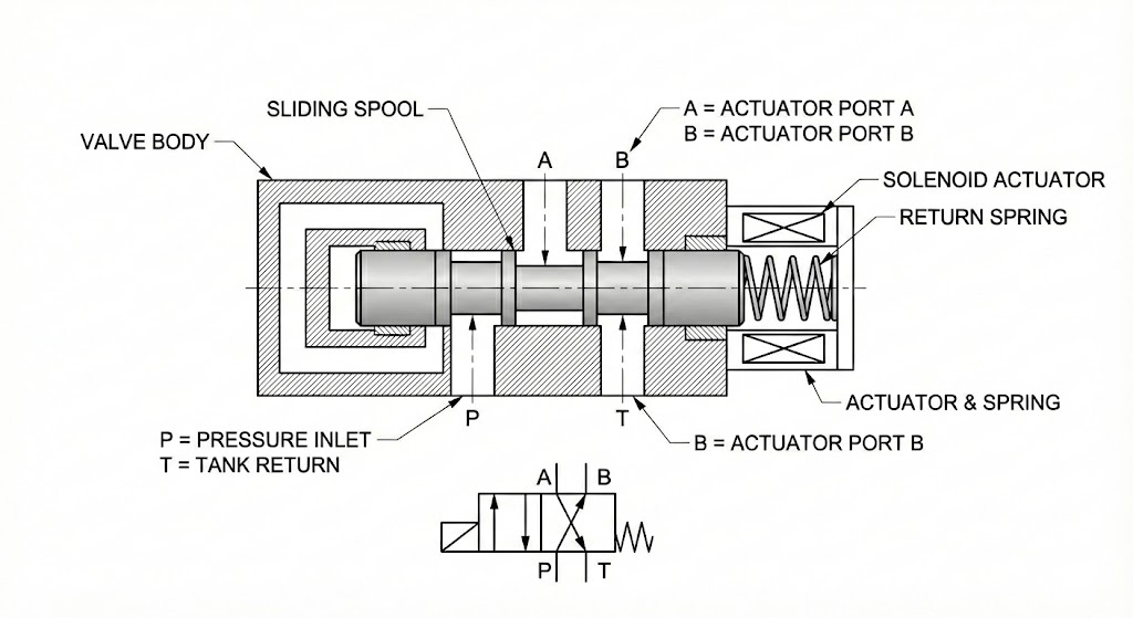
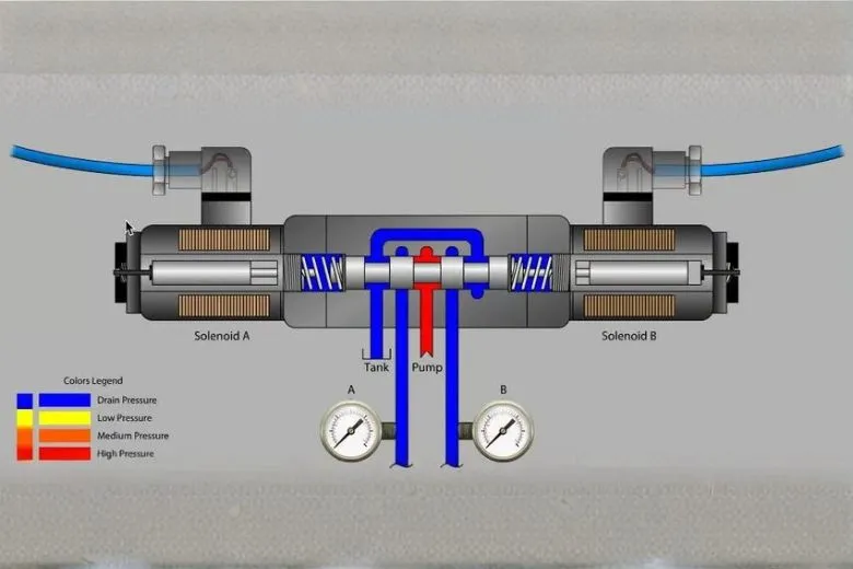
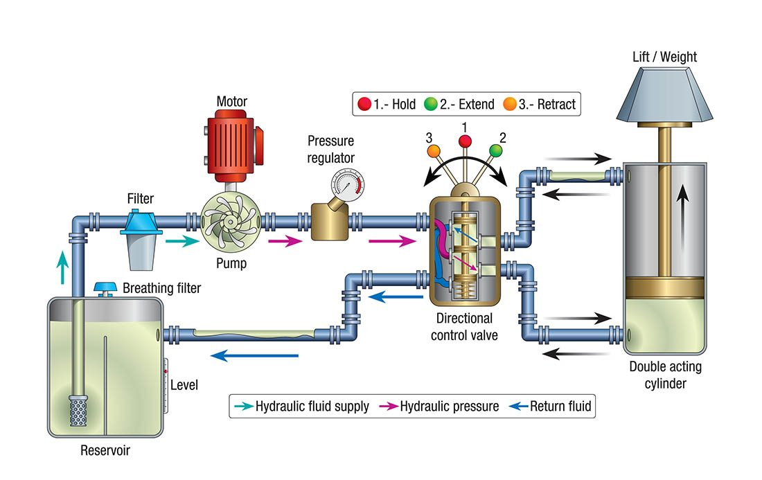
A directional control valve routes pressurized hydraulic fluid to cylinders and motors — it decides which way things move, how fast, and when they stop. When one fails, the downstream effects ripple through the entire circuit: cylinders stall, loads drift, cycle times stretch, and operators start complaining about something that feels "off" but is hard to describe. Understanding how directional control valves work at the spool level makes troubleshooting far more intuitive, because every symptom connects to a specific mechanical or hydraulic root cause inside that valve body.
Industry data consistently points to contaminated hydraulic fluid as the dominant failure driver. Particles as small as 10 microns — invisible to the naked eye — wedge between spool lands and the bore, scoring precision surfaces that were machined to single-digit micron tolerances. Thermal degradation, water ingress, and chemical breakdown of the oil compound the damage.
One thing worth saying upfront: not every symptom that looks like a directional valve problem actually starts there. Pressure loss from a misadjusted relief valve, a worn pump, or a blown cylinder seal can all masquerade as a "dead" or "sluggish" directional valve. The troubleshooting approach in this guide assumes you'll rule out the upstream causes before condemning the valve itself — and Problem 5 below covers that crossover in detail.
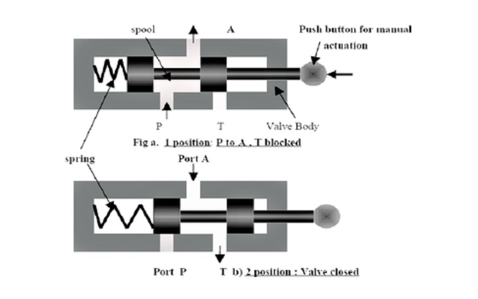
This one hits hard and fast. You command the valve to shift, and nothing happens — or the spool moves partway and jams. On a production floor, a stuck directional valve can halt an entire press line in seconds.
Metal shavings, sand, or wear debris lodged between the spool and bore physically block movement. The spool-to-bore clearance on a typical industrial directional valve runs between 5 and 15 microns. A single particle larger than that gap turns a smooth-sliding spool into a jammed piston. Forcing the lever or cranking up solenoid voltage will only gouge the bore walls, creating a cycle of escalating damage that ends with complete valve replacement.
The correct fix is disassembly and thorough cleaning. Remove the spool, flush the bore with clean solvent, inspect all land surfaces under magnification for scoring, and reassemble with fresh seals. If the bore shows visible scratches you can catch with a fingernail, the valve body is compromised.
Silting operates more slowly than hard contamination but produces the same result. Soft deposits — oxidized oil byproducts, varnish, and sludge — accumulate on spool lands and hydrostatic bearing surfaces. The sliding friction gradually increases until the operator force (whether solenoid, lever, or pilot pressure) can no longer overcome it. Systems running at elevated temperatures accelerate varnish formation dramatically; every 18°F above optimal operating temperature roughly doubles the rate of oil degradation.
Cleaning the spool and bore with an appropriate solvent restores function, but the real fix is upstream: address the thermal condition, change the fluid, and tighten your filtration. A system running hot enough to varnish its valves is probably degrading every other component simultaneously.
Springs, detent balls, centering pins, and washers inside the valve are small and under constant cyclic stress. A broken centering spring lets the spool hang in a partially shifted position. A shattered detent ball jams the spool mid-stroke. These failures require the valve to come apart on a clean bench — there is no field workaround that will hold long-term.
Internal leakage is the quiet killer. There are no puddles on the floor, no drips to spot with a flashlight — just a cylinder that slowly sinks under load, cycle times that creep upward week after week, and oil temperatures that climb for no apparent reason. Recognizing the early signs of a failing hydraulic control valve can save thousands in emergency repairs and unplanned downtime.
Here is what happens mechanically: as the spool lands and bore wear, the clearance between them widens. Pressurized fluid that should be blocked finds a shortcut back to the tank port. That bypassing oil converts hydraulic energy directly into heat — every drop leaking through represents wasted work. On a system running at 3,000 PSI, even a small increase in internal clearance produces measurable temperature rise and noticeable performance loss.
The diagnostic approach is straightforward. Command the cylinder to hold position under load and shut off the directional valve. If the cylinder drifts, either the valve or the cylinder seals are leaking internally. To isolate which one, disconnect the cylinder lines at the valve and cap the cylinder ports. If the cylinder holds now, the directional valve is your problem. If it still drifts, you are looking at blown piston seals.
There is a faster screening method that doesn't require any disassembly. Grab an infrared thermometer and scan the return lines coming off each directional control valve in the circuit. Under normal conditions, return lines run warm — maybe 10–20°F above ambient. A return line that's significantly hotter than its neighbors is carrying flow it shouldn't be. This technique pinpoints the leaking valve without pulling a single fitting.
Unfortunately, worn spool-to-bore clearances cannot be repaired in the field. Unlike external seals that can be swapped, the precision fit between spool and bore is a matched assembly. The only permanent fix is valve replacement with a unit that meets OEM clearance specifications.
External leaks at least have the courtesy of being visible. Oil weeping from shaft seals, solenoid tube joints, or subplate gaskets tells you exactly where to start.
Seal degradation is the most frequent cause — O-rings and shaft seals harden and crack over time, especially in systems that run hot or use incompatible fluids. Push-pin seals on manually operated spools wear from repetitive cycling. Solenoid core tube seals can fail if the tube itself corrodes or takes side-load stress from misaligned mounting.
One design consideration worth noting: monoblock valve construction inherently reduces external leak paths compared to stackable (sectional) designs, which require O-ring seals between each section. If your application uses a multi-spool setup and inter-section leaks are a recurring headache, a one-piece monoblock body eliminates those joints entirely.
Most external leaks are field-repairable: replace the seal, torque the fasteners to manufacturer specification, and verify the repair under pressure. One exception — if the seal groove or the spool bearing surface is physically worn or scored, the leaking will return within days. At that point, the valve needs replacement, not another seal kit.
Before tearing into hydraulic internals, check the wiring. A significant percentage of "dead valve" calls turn out to be electrical faults — a burned solenoid coil, a corroded connector, a dropped wire, or a PLC output that never fired.
Grab a multimeter. Measure voltage at the solenoid terminals while the control signal is active. Compare that reading against the coil's rated voltage (typically 12V DC, 24V DC, or 110V AC on most industrial directional valves). Next, check coil resistance — a reading that's open (infinite) or near-zero indicates a failed winding. A coil can look perfectly fine on the outside and be dead inside.
Every solenoid-operated directional valve has a manual override button — a small pin or push-button accessible with a screwdriver. Press it. If the cylinder responds normally, your hydraulics are healthy and the fault is purely electrical. This 30-second test eliminates hours of unnecessary hydraulic disassembly.
Solenoid burnout can also be a secondary symptom. A spool that is mechanically stuck forces the coil to draw current continuously without completing its stroke. The coil overheats and fails. In this scenario, simply replacing the coil without addressing the underlying spool contamination will result in repeat burnout — sometimes within days.
The valve shifts, but sluggishly or inconsistently. Cylinders jerk instead of gliding. Pressure readings swing where they should hold steady. These symptoms often point to partial contamination in pilot passages, weak return springs, or degraded fluid viscosity.
Pilot-operated directional valves are particularly susceptible. The pilot stage uses tiny orifices — sometimes less than 1 mm in diameter — to sense and route control pressure. A single particle lodged in a pilot orifice can degrade shifting speed or cause the main spool to hang in a partially open position. Flushing the pilot section and verifying orifice cleanliness resolves most intermittent shifting problems.
Low system pressure can mimic directional valve faults convincingly. If response is sluggish across the board, the issue is likely upstream — a worn pump, a misadjusted or failed relief valve, or a restriction at the pump inlet. Always verify system pressure at the valve inlet before concluding the directional valve itself is at fault.
This is a pattern we see regularly in support calls. A steel fabrication shop recently contacted us about a press brake losing clamping force — the crew had already replaced the hydraulic pump, but pressure was still well below setpoint. The actual culprit turned out to be a pilot-operated relief valve with a hairline crack in its pilot piston seat, dumping flow to tank prematurely. Total cost of the real fix was a fraction of the pump replacement they'd already paid for. The lesson: a dead-head test at the pump outlet, followed by careful relief valve inspection, should always come before condemning downstream directional valves. For a full walkthrough of that diagnostic sequence, see our low-pressure troubleshooting guide.
Since contamination drives the majority of directional control valve failures, the most cost-effective "fix" is preventing particles from reaching the valve in the first place. An effective contamination control program includes these essentials:
Filtration rated to your valve tolerances. For spool valves with 5-15 micron clearances, a 10-micron absolute return-line filter is the minimum. Systems with proportional or servo valves should target 3-5 microns. Change filter elements based on differential pressure indicators, not arbitrary calendar schedules — a filter running past its bypass point circulates unfiltered oil.
Regular fluid analysis. An annual or semi-annual oil sample sent to a testing lab costs under $30 and reveals particle counts, water content, viscosity shift, and chemical breakdown before any of these conditions reach failure thresholds.
Sealed reservoirs and clean fill practices. Contamination enters through breather caps, open fill ports, and dirty transfer containers more often than it's generated internally. A desiccant breather on the reservoir and a dedicated transfer pump with an inline filter eliminate two of the largest ingression paths.
Temperature management. Keep oil temperature within the 100-140°F operating window. Overheating accelerates oxidation, thins the fluid, and increases internal leakage across every valve and cylinder in the circuit. If temperatures are climbing, check the cooler, fan motor, and thermostat before blaming the valves.
Not every failing valve needs to be scrapped. External seal leaks, solenoid coil failures, broken springs, and contamination-related sticking are all repairable — often on-site — with the correct seal kits and spare parts. For a deeper look at what's involved when a valve needs bench work, our guide on main control valve repair covers the process from teardown to testing.
Replacement becomes necessary when internal bore-to-spool clearances have worn beyond specification, when the valve body is cracked or scored, or when repeated contamination damage has created a surface finish that no amount of cleaning will restore. On mobile equipment logging 6,000+ hours, valve wear is cumulative and eventually irreversible.
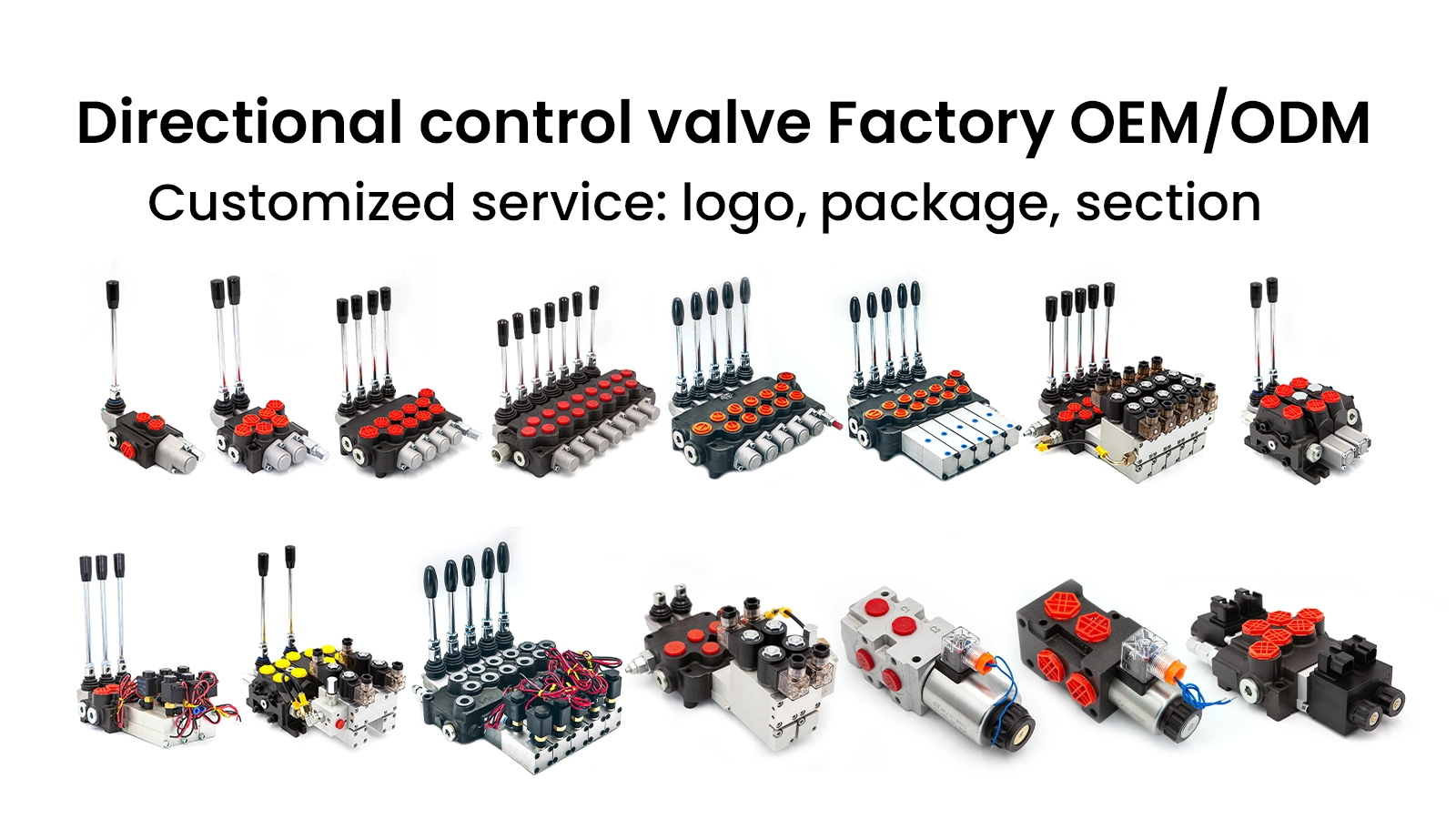
When sourcing a replacement, match the original specifications precisely: flow rating, pressure rating, port configuration, spool center type (open, closed, tandem, or float), and actuation method. A valve that's "close enough" can create entirely new problems. For multi-function mobile machines, a P80 monoblock directional control valve is a compact alternative to stackable designs — the one-piece body eliminates inter-section leak paths and is available in 1- through 6-spool configurations with a built-in adjustable relief valve. For lighter systems under 40 L/min, the P40 series covers the same ground in a smaller package.
The most common cause is particulate contamination lodged between the spool and bore. Hard particles (metal shavings, sand) jam the spool mechanically, while soft contaminants (varnish, sludge) increase sliding friction until the actuator force cannot overcome it. Broken internal springs and detent mechanisms are less common but produce the same symptom. Always check the manual override first to rule out electrical faults before disassembling the hydraulic section.
Look for these indicators: cylinders that drift under static load, progressively slower cycle times, and hydraulic oil temperatures climbing without a corresponding increase in workload. To confirm, hold the cylinder under load, shut off the valve, and monitor for drift. Isolate the cylinder from the valve by capping lines to determine whether the valve or the cylinder seals are responsible.
Many failures are repairable. External seal leaks, burned solenoid coils, broken springs, and contamination-induced sticking can all be addressed with proper cleaning, seal kits, and replacement parts. However, if the spool-to-bore clearance has worn beyond the manufacturer's tolerance — typically indicated by persistent internal leakage after cleaning — the valve must be replaced as a matched spool-and-body assembly.
In clean, well-maintained systems, annual inspections are typically sufficient. Systems operating in harsh environments (mining, demolition, outdoor mobile equipment) benefit from quarterly visual checks and semi-annual functional tests. Any time system contamination is suspected — after a hose burst, pump failure, or reservoir breach — inspect and flush all directional valves immediately, regardless of schedule.
ISO 4406 cleanliness code 18/16/13 is adequate for standard spool valves. Proportional and servo directional valves require cleaner fluid — target 16/14/11 or better. Achieving these levels demands properly sized filtration (10 micron absolute for standard, 3-5 micron for proportional) and disciplined fluid management practices including sealed reservoirs, desiccant breathers, and clean-fill procedures.
If you've worked through the steps above and still can't isolate the fault, contact our technical team — we can help with model verification, fault diagnosis, and sourcing the right replacement parts from our hydraulic valve catalog.